Table of Contents
Advertisement
Quick Links
Advertisement
Table of Contents

Related Manuals for VIA Technologies K8T800


Summary of Contents for VIA Technologies K8T800
- Page 1 VIA K8T800 + VT8237R ATX Motherboard User’s Guide...
- Page 2 Declaration of Conformity According to 47 CFR, Parts 2 and 15 of the FCC Rules The following designated product: EQUIPMENT: MAINBOARD is a Class B digital device that complies with 47 CFR Parts 2 and 15 of the FCC Rules. Operation is subject to the following two conditions: 1.
- Page 3 Federal Communications Commission Statement This device complies with FCC Rules Part 15. Operation is subject to the following two conditions: * This device may not cause harmful interference. * This device must accept any interference received, including interference that may cause undesired operation.
-
Page 4: Table Of Contents
TABLE OF CONTENTS CHAPTER 1 INTRODUCTION ....................1 1-1 S PECIFICATIONS ........................1 1-2 P ACKAGE ONTENTS ......................2 1-3 B ANEL .......................... 2 CHAPTER 2 HARDWARE SETUP ..................3 2-1 PC D.I.Y. A SSEMBLY NSTRUCTIONS ................... 3 2-2 自行組裝電腦之作業指導重點 (C ) ................. - Page 5 REVISION HISTORY Revision Description V.1S_M Original Issue 9413387110...
-
Page 7: Chapter 1 Introduction
Chapter 1 Introduction 1-1 Specifications - Supports AMD Socket-754 Athlon 64/Sempron CPU - Processor interface via 6.4GB/s HyperTransport bus Chipset - VIA K8T800+ VT8237R Memory - Two 184- pin DDR DIMMs up to 2GB - Supports DDR266/333/400 memory Expansion Slots - One AGP slot for 8X/4X AGP - Five 32-Bit PCI slots (v2.2 compatible) -
Page 8: Package Contents
Chapter 1 1-2 Package Contents This product comes with the following components: 1. 1 x Motherboard 2. 1 x 40-Pin UDMA-100 IDE Cable Blue to motherboard, Gray to Master and Black to Slave 3. 1 x 34-Pin floppy Disk Drive Cable 4. -
Page 9: Chapter 2 Hardware Setup
Chapter 2 Chapter 2 Hardware Setup 2-1 PC D.I.Y. Assembly Instructions 1. Jumper Setting: Set the CPU External Clock, Frequency Ratio and the CPU voltage according to the instruction printed on the manual or silkscreen printed on the mainboard. 2. Installing FDD and IDE devices: Aligned the red colored edge of the cable with the pin 1 of the drive connector on the mainboard and gently attached it. - Page 10 Chapter 2 5. Mounting a Mainboard into a Chassis: Use standoffs and screws to securely mount the mainboard and make sure that all the mounting holes are properly screwed. 6. Adding an expansion card: Gently fasten the card to the proper slot. 7.
-
Page 11: 自行組裝電腦之作業指導重點
Chapter 2 2-2 自行組裝電腦之作業指導重點 (Chinese) 1. 主機板硬體組態設定: 依據使用手冊上面的指令或印刷在主機板上的文字來設定 CPU 外頻,倍頻及電壓或其它設定。 2. 安裝 FDD 和 IDE 裝置: 將排線較長一端的排線插入主機板 IDE 插槽並且紅色線對準插槽的第一針腳 (Pin 1),檢視排線接頭是否完全插入插槽,同時排線較短的一端也依序插入軟碟機,硬碟機等儲存裝置。 3. 安裝 CPU: 將 CPU 的缺角對準 CPU 腳座的缺角並小心地將 CPU 插在腳座上,按下旁邊的固定桿以固定 CPU。 4. 安裝系統記憶體: 先確定記憶體模組金手指的方向,慢慢插入記憶體插槽並小心地將記憶體模組往下壓,直到插槽的固定卡 榫卡住記憶體模組兩端的缺口。... - Page 12 Chapter 2 5. 主機板固定: 用銅柱及螺絲將主機板安裝在機殼底座並確定每個孔洞均已被鎖上,尤其注意主機板底下不可有多餘的銅 柱以避免造成短路。 6. 增加介面卡: 將介面卡(例 : 網路卡,音效卡等)插在適當的介面卡擴充插槽,並將卡上的鐵片鎖緊在機殼上。 7. 連接 I/O 埠和其他設備的接頭: 適當地將排線插入各設備的插槽,記得必須將排線與插座的第一針腳互相對準,請參照使用者手冊的主機 板平面圖。 8. 連接電源供應器: 將電源接頭與主機板上之插座對準插入,並確定卡榫已緊扣。...
-
Page 13: Français Instructions De Montage Du Pc D.i.y (French)
Chapter 2 2-3 Français Instructions de montage du PC D.I.Y (French) 1. Positionnement des cavaliers (jumpers) Positionnez les cavaliers de la fréquence d’horloge externe du microprocesseur, du rapport de fréquence et de la tension d’alimentation du microprocesseur, suivant les instructions qui figurent dans le manuel ou qui sont sérigraphiées sur la carte mère. - Page 14 Chapter 2 5. Montage d’une carte mère dans son châssis A l’aide des jauges d’espacement et des vis fournies, fixez fermement la carte mère dans son emplacement, et vérifiez que tous les trous destinés à la fixation sont utilisés et les vis sont correctement serrées.
-
Page 15: Deutsch Pc D.i.y.-Montageanleitung (German)
Chapter 2 2-4 Deutsch PC D.I.Y.-Montageanleitung (German) 1. Steckbrücken Konfigureren Die Anweisungen zum Einstellen des externen Prozessortakts, der Taktfrequenz und der Prozesorspannung finden Sie im Hand buch oder direct auf dem Motherboard. 2. Disketten- und Festplattenlaufwerke Installieren Schließen Sie die rot markierte Kabelseite an Stift 1 des Laufweksanschlußes auf dem Motherboard an. - Page 16 Chapter 2 5. Motherboard im Gehäuse montieren Verwenden Sie das modul nach Schraubenund Abstandhalter, um das Motherboard stabil im Gehäuse zu montieren. Achten Sie darauf, daß sämtliche Montagöffnungen korrekt miet einer Schraube versekhen werden. 6. Steckkarte einbauen Führen Sie die Karte vorsichtig in einen geeingneten Steckplatz ein. 7.
-
Page 17: Самостоятельная Сборка Пк (Russian)
Chapter 2 2-5 Самостоятельная сборка ПК (Russian) 1. Установка перемычек Установите параметры Вашего таймера ЦПУ, значение частоты и напряжение ЦПУ согласно инструкциям, приведенным в руководстве, или надписям на системной плате. 2. Установка Накопителя на гибких дисках и IDE устройств Совместите кромку красного цвета кабеля и PIN1 разъема накопителя на системной плате, затем... - Page 18 Chapter 2 5. Монтаж системной платы на шасси Для надежного монтажа системной платы используйте крепления и винты. Убедитесь, что все монтажные отверстия закреплены винтами. 6. Установка карт расширения Аккуратно установите карту в соответствующий слот 7. Подсоединение портов ввода/вывода и разъемов устройств Подсоедините...
-
Page 19: Pc D. I. Y. 조립 설명 (Korean)
Chapter 2 2-6 PC D. I. Y. 조립 설명 (Korean) 1.점퍼설정 매뉴얼이나 메인보드에 나와있는 설정방법을 참고하여 CPU 의 외부클럭, 주파수, 전압 등을 설정합니다. 2. 메인보드 장착 드라이버를 이용하여 케이스에 정확하게 메인보드를 장착합니다. 3. CPU 장착 CPU 의 모서리를 보면 표시가 되어있습니다. 이 부분이 1 번 핀입니다. 이 부분을 메인보드의 CPU 소켓에... - Page 20 Chapter 2 5. 플로피 디스크, 하드디스크 케이블 연결 케이블의 1 번선은 빨간색입니다. 이 선을 기준으로 하여 메인보드의 1 번핀에 정확하게 장착합니다. 커넥터가 확실하게 연결될 수 있도록 하십시오. 6. 외부 카드의 장착 비디오카드 및 다른 외부 장착용 카드를 장착합니다. 7. I/O 포트, 기타장치 연결 매뉴얼이나...
-
Page 21: Connector And Jumper Settings
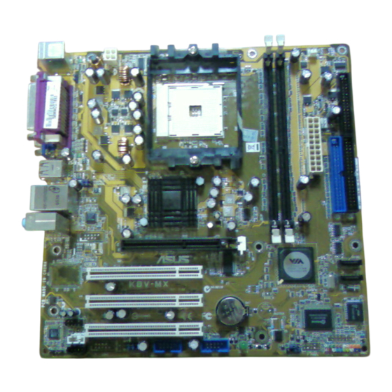
Chapter 2 2-7 Connector and Jumper Settings Connectors are used to link the system board with other parts of the system, including power supply, keyboard, and the various controllers on the front panel of the system case. The power supply connector is the last connection to be made while installing a motherboard. - Page 22 Chapter 2 CN1A (Front Panel Connector): PWR-SW (Over-ride Power Button Connector): The power button on the ATX chassis can be used as a normal power switch as well as a device to activate the Advanced Power Management Suspend mode. This is a power-saving mode used for saving electricity when the computer is idle for long periods of time.
- Page 23 Chapter 2 FDD1 (Floppy Connector): The motherboard provides a standard floppy disk drive connector that supports 360K, 720K, 1.2M, 1.44M and 2.88M floppy disk types. It is connected to a floppy disk drive of 34 pins. IDE 1/2 (IDE Hard-Disk Connector): The motherboard has a 32-bit Enhanced PCI IDE and Ultra ATA66/100/133 controller that provides PIO mode 0~4, Bus Master, and Ultra ATA66/100/133 function.
- Page 24 Chapter 2 JP6 (Enable/Disable USB 0/1 Device Wake-Up Jumper): An USB keyboard hot key or an USB mouse-click can activate Definition this board. To use this function, select a hot key of your choice Disable (default) at the USB Resume from S3 option under Wake Up Events in Enable the BIOS's Power On Management screen.
- Page 25 Chapter 2 CN17 (Blue LED Connector) This feature works exactly the same as the power Definition indicator LED, of which both indicate the system’s CHAINTECH (default) power status. The only difference is that this one is blue while the other one is red. CN23 / 23A/ 23B (USB Connector for USB 2/3, 4/5 and 6/7): USB Port 2/3 ->...
-
Page 26: Chapter 3 Bios Setup Program
Chapter 3 Chapter 3 BIOS Setup Program Phoenix-Award BIOS ROM has a built-in setup program that allows users to modify the basic system configuration. This information is stored in CMOS RAM so that it can retain the setup information even when the power is turned off. Press [Delete] when you Power on or Reboot the computer system..The primary screen as shown in Figure 3-1 is a list of the menus and functions available in the setup program. -
Page 27: Integrated Peripherals
Chapter 3 3-4 Integrated Peripherals This section provides information on setting up the peripheral devices. 3-5 Power Management Setup This section provides information on the Green PC power management functions. 3-6 PNP/PCI Configurations This section provides IRQ and DMA settings information. 3-7 Frequency/Voltage Control This section allows users to adjust the frequency/voltage control of the motherboard. -
Page 28: Save And Exit Setup
Chapter 3 3-11 Save and Exit Setup If you select this and type [Y] followed by [Enter], the values entered in the setup utilities will be recorded in the CMOS memory of the BIOS chip. 3-12 Exit Without Saving Selecting this option and pressing [Y] followed by [Enter] lets you exit the Setup program without recording any new values or changing old ones. -
Page 29: Chapter 4 Driver Setup
Chapter 4 Chapter 4 Driver Setup Insert the support CD that come with your motherboard into your CD-ROM driver or double-click the CD drive icon in [My computer] to enter the setup screen. 4-1 VIA Driver Setup 1. Click [VIA Service Pack]. 2. -
Page 30: Usb 2.0 Driver
Chapter 4 4-5 USB 2.0 Driver 1. Click [USB 2.0 Driver] to start the installation. 2. Click [Next >] to begin the installation. 3. Select [Install USB Driver] and click [Next >] to proceed. 4. Select [Yes, I want to restart my computer now] or [No, I will restart my computer later] and then click [Finish] to complete the setup process. -
Page 31: Appendix
Appendix Appendix For Windows 2000/XP Server SATA setup instruction After you unpack driver, please copy files & subdirectories under directory D:\Raid\Via\DriverDisk (assuming your optical drive is D) to the root directory of floppy diskette (called driver diskette). Therefore, in root directory of floppy diskette you will see: (1) Files "txtsetup.oem", (2) Directory "RAID", “PIDE"and related driver files in each directory. - Page 32 Note NOTE All rights are reserved for the products and corporate names/logos that appear in this manual to their original owners. We reserve all rights to change this manual. All information is subject to change without notice.
- Page 33 How To Contact CHAINTECH How To Contact CHAINTECH Please do not hesitate to contact us if you have any problem about our products. Any opinion will be appreciated. <Headquarters> For France, Europe: For Asia, Africa, Australia and Pacific AELT COMPUTER Island: 5 rue de Rome 93561 Rosny Sous Bois CHAINTECH COMPUTER CO., LTD...
Need help?
Do you have a question about the K8T800 and is the answer not in the manual?
Questions and answers