Table of Contents
Advertisement
Quick Links
User'
User' s s s s s
User'
User'
User'
Manual
Manual
Manual
Manual
Manual
VIA
VIA
KT880
KT880
VIA KT880
VIA
VIA
KT880
KT880 mainboard
for AMD Socket A processor
for AMD Socket A processor
for AMD Socket A processor
for AMD Socket A processor
for AMD Socket A processor
TRADEMARK
All products and company names are trademarks or registered
trademarks of their respective holders.
These specifications are subject to change without notice.
mainboard
mainboard
mainboard
mainboard
Manual Revision 1.0
September 06, 2004
Advertisement
Table of Contents

Related Manuals for VIA Technologies KT880


Summary of Contents for VIA Technologies KT880
- Page 1 Manual Manual Manual Manual Manual KT880 KT880 mainboard mainboard VIA KT880 KT880 KT880 mainboard mainboard mainboard for AMD Socket A processor for AMD Socket A processor for AMD Socket A processor for AMD Socket A processor for AMD Socket A processor...
- Page 2 DISCLAIMER OF WARRANTIES: THERE ARE NO WARRANTIES WHICH EXTEND BEYOND THE DESCRIPTION ON THE FACE OF THE MANUFACTURER LIMITED WARRANTY. THE MANUFACTURER EXPRESSLY EXCLUDES ALL OTHER WARRANTIES, EXPRESS OR IMPLIED, REGARDING ITS PRODUCTS; INCLUDING ANY IMPLIED WARRANTIES OF MERCHANTABILITY, FITNESS FOR A PARTICULAR PURPOSE OR NONINFRINGEMENT.
-
Page 3: Table Of Contents
Table of Contents Page Section 1 Introduction Package Contents ............1- 1 Mainboard Features ........... 1- 2 System Block Diagram ..........1- 4 Section 2 Specification Mainboard Specification ..........2- 1 Section 3 Installatio Mainboard Layout ............. 3- 1 Easy Installation Procedure ........3- 2 CPU Insertion ............. - Page 4 PC Health Status ............4- 19 Power BIOS Features ..........4- 20 Defaults Menu ............4- 22 Supervisor/User Password Setting ......4- 23 Exit Selecting .............. 4- 24 Section 5 S-ATA RAID Configuration Introduction ............... 5- 1 VIA S-ATA RAID Features ........5- 3 Enable RAID Function ..........
-
Page 5: Introduction
Introduction Section 1 INTRODUCTION 1-1 Package Contents Contents Optional Items A. Mainboard G. S-ATA data and power cable B. User’s manual H. Extra USB2.0 port cable C. Floppy drive cable I. S/PDIF Module D. HDD drive cable If you need the optional item, please contact your dealer for assistance. -
Page 6: Mainboard Features
AMD website at http://www.amd.com Chipset The board is designed with VIA chipset, KT880 as North Bridge and VT8237 as South Bridge, providing a feature rich and scalable platform. The North Bridge connects to the South Bridge through the fast Ultra V-Link connection at 1.06GB/s. - Page 7 Introduction 10/100 LAN This mainboard is mounted with an ethernet LAN PHY. It allows the mainboard to connect to a local area network by means of a network hub. Serial ATA Support Serial ATA, an evolutionary replacement for Parallel ATA IDE storage interface .Increases the peak data transfer speed up to 150MB/sec and allows future enhancements to the computing platform.
-
Page 8: System Block Diagram
Introduction 1-3 System Block Diagram Page 1-4... -
Page 9: Specification
Supports 462-pin Socket A for AMD Athlon XP processors with up to 400MHz FSB Athlon XP (1500+ to 3200+) @266/333/400MHz Front Side Chipset VIA AGPset : VIA KT880 + VT8237 Main Memory 184-pin DDR DIMM sockets Support single-sided or double-sided 2.5v DDR-266/333/400 DIMMs with... -
Page 10: Legacy Io Controller
Specification Legacy IO Controller Winbond W83687THF LPC IO controller with floppy, printer, game, serial and SIR interface Supports Hardware Monitoring function Audio channel audio with analog and digital output using Realtek ALC655 AC’97 CODEC - AC’97 v2.3 compliant - Supports CD-In, AUX-IN and S/PDIF-in/out interface - Supports Line-out and Mic-In for front panel - Supports automatic “Jack-sensing”... - Page 11 Specification CD-IN and One AUX-IN connectors S/PDIF in/out connector IR connector S-ATA connectors Three Fan connectors Front Panel Controller Supports Reset & Soft-Off switches Supports HDD & Power LEDs Supports PC speaker Supports Front Panel Audio connector Expansion Slots AGP slot supporting 1.5v 4X/8X AGP card - AGP v3.0 compliant...
- Page 12 Specification Page 2-4...
-
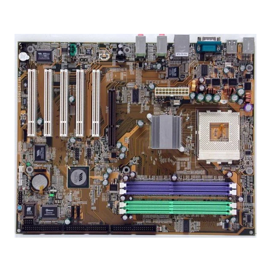
Page 13: Installation
Installation Section 3 INSTALLATION Mainboard Layout <Figure 1> Page 3-1... -
Page 14: Easy Installation Procedure
Installation Easy Installation Procedure The following must be completed before powering on your new system: 3-1. CPU Installation 3-2. Jumper Settings 3-3. System Memory Configuration 3-4. Expansion Slots 3-5. Device Connectors 3-1 CPU Installation CPU Insertion: (use AMD Athlon as reference) Step 1 Open the socket by raising the actuation lever. - Page 15 Installation Step 3 Close the socket by lowering and locking the actuation lever. <Figure 4> Step 4 Install the CPU heatsink as shown in Figure 5. Thermal compound and qualified heatsink recommended by AMD are a must to avoid CPU overheat damage. For more information about installing your CPU, please refer to the AMD website article “Socket A AMD processor and Heatsink Installation Guide”...
-
Page 16: Jumper Settings
Installation 3-2 Jumper Settings JCMOS1: Clear CMOS data Jumper If the CMOS data becomes corrupted or you forgot the supervisor or user password, clear the CMOS data to reconfigure the system back to the default values stored in the ROM BIOS. Settings: 1-2: Normal (Default) 2-3: Clear CMOS... -
Page 17: System Memory Configuration
Installation 3-3 System Memory Configuration Memory Layout The mainboard accommodates three PC2100/PC2700/PC3200 184-pin DIMMs (Dual In-line Memory Modules): • Supports up to 2.0GB of 266/333/400MHz DDR SDRAM • Supports up to 2 DDR DIMMs (refer to Table 1) • Supports 64/128/256/512Mb, 1Gb x8 & x16 DRAMs •... -
Page 18: Expansion Slots
Installation 3-4 Expansion Slots AGP Slot The mainboard is equipped with an AGP slot. Make sure you install a card that supports the 1.5V specification. PCI Slots The mainboard is equipped with 5 PCI AGP Slot slots. PCI Slots AGP Card Installation Caution When installing the AGP card make sure the AGP card edge connector is inserted fully into the slot and the slot clicker is locked. -
Page 19: Device Connectors
Installation 3-5 Device Connectors The I/O back panel for this mainboard is shown below. When installing the mainboard into the computer case, use the bundled I/O shield to protect this back panel. RJ45 Parallel Port Line-in/Rear out (Blue) PS/2 Mouse Line-out/Front out (Green) PS/2 Mic-in/Center&Subwoofer (Pink) - Page 20 Installation Floppy Controller Connector FDD1 This connects to the floppy disk drive. IDE1/IDE2:Ultra DMA-100/133 Primary/Secondary IDE1IDE2 IDE Connector This mainboard is equipped with 2 IDE connectors to support up to 4 ATA-133 IDE drives. It supports PIO and DMA mode operations for maximum data transfer rate of 133MB/sec per channel.
- Page 21 Installation CFPA1: Front Panel Audio Connector When the jumpers are removed this connector can be used for front panel audio. The front panel phone jack should have “normal close” switch. Without phone plug inserted, the rear panel audio is enabled. With phone plug inserted, the rear panel audio will be disabled.
- Page 22 Installation SPDIF1: Sony/Philips Digital InterFace connector This connector links digital audio between the mainboard and your audio devices, such as CD player, sampler or DAT recorder. It allows the digital transmission of audio data in S/PDIF format. SPDIF_IN SPDIF_OUT SATA1 / SATA2: Serial ATA Connectors These connectors enable you to connect Serial ATA devices that conform to the Serial ATA specification.
- Page 23 Installation CFP1: Front Panel Connector HD_LED This LED will light up whenever the hard drive is being accessed. PWR_LED This connects to the power button of the system chassis This switch allows you to reboot without having to power off the system thus prolonging CFP1 the life of the power supply or system.
-
Page 24: Power-On/Off (Remote)
Installation 3-6 Power-On/Off (Remote) This board has a 20-pin ATX and a 4-pin ATX12V power supply connector to support power supplies with Remote On/Off feature. The 4-pin ATX12V connector must be plugged in for the system to operate safely. The chassis power button should be connected to the mainboard front panel PW_ON header (Figure 8). - Page 25 Installation 3-8 ACPI S3 (Suspend To RAM) Function This mainboard supports the STR (Suspend To RAM) power management scheme by maintaining the appropriate power states in the DDR SDRAM interface signals. The power source to the DDR SDRAM is kept active during STR (ACPI S3).
- Page 26 Installation Page 3-14...
-
Page 27: Bios Setup
BIOS Section 4 BIOS SETUP Main Menu The ROM BIOS contains a built-in Setup program which allows user to modify the basic system configuration and hardware parameters. The modified data is stored in a battery-backed CMOS, so that data will be retained even when the power is turned off. -
Page 28: Standard Cmos Setup
BIOS The main menu displays all the major selection items. Select the item you need to reconfigure. The selection is made by moving the cursor (press any direction (arrow key ) to the item and pressing the ‘Enter’ key. An on-line help message is displayed at the bottom of the screen as the cursor is moved to various items which provides a better understanding of each function. -
Page 29: Advanced Bios Features
BIOS 4-2 Advanced BIOS Features Selecting the “ADVANCED BIOS FEATURES” option in the CMOS SETUP UTILITY menu allows users to change system related parameters in the displayed menu. This menu shows all of the manufacturer’s default values for the board. Pressing the [F1] key displays a help message for the selected item. - Page 30 BIOS Quick Power On Self Test This category speeds up the Power On Self Test (POST), select “Enabled” will shorten or skip of the items checked during POST. Options: Enabled, Disabled. First /Second/Third Boot Device The BIOS attempts to load the operating system from the devices in the sequence selected in these items.
-
Page 31: Advanced Chipset Features
BIOS Software resides on both the disk drive and the host computer. Options: Enabled, Disabled. Video BIOS Shadow This option allows video BIOS to be copied into RAM. Video Shadowing will increase the video performance of your system. Options: Enabled, Disabled. Full Screen LOGO Show This item allows you determine Full Screen LOGO display during POST. - Page 32 BIOS Video RAM Cacheable This option allows the CPU to cache read/writes of the video RAM. Options: Disabled, Enabled. Top Performance This item will enhance the memory performance. We recommend you leave “Disabled” at the default value. Selecting “Enabled” may cause instability. Options: Disabled, Enabled.
- Page 33 BIOS Bank Interleave This item allows you to set how many banks of DRAM support in your mainboard. Options: Disabled, 2 Bank, 4 Bank. Precharge to Active (Trp) This item refers to the number of cycles required to return data to its original location to close the bank or the number of cycles required to page memory before the next bank activate command can be issued.
- Page 34 BIOS AGP & P2P Bridge Control Scroll to AGP & P2P Bridge Control and press <Enter>. The following screen appears: AGP Aperture Size (MB) This item defines the size of the aperture if you use an AGP graphics adapter. It refers to a section of the PCI memory address range used for graphics memory.
- Page 35 BIOS CPU & PCI Bus Control Scroll to CPU & PCI Bus Control and press <Enter>. The following screen appears: PCI1/2 Master 0 WS Write When Enabled, Writes to the PCI bus are commanded with zero wait states. Options: Enabled, Disabled. PCI1/2 Post Write Enables CPU to PCI bus POST write.
-
Page 36: Integrated Peripherals
BIOS 4-4 Integrated Peripherals Figure 5: Integrated Peripherals VIA OnChip IDE Device Scroll to VIA OnChip IDE Device and press <Enter>. The following screen appears: SATA Mode This item allows you to set RAID mode for Serial ATA devices. Options: RAID, IDE. OnChip SATA Enables the onboard SATA feature. - Page 37 BIOS IDE DMA transfer access Automatic data transfer between system memory and IDE device with minimum CPU intervention. This improves data throughput and frees CPU to perform other tasks. Options: Enabled, Disabled. OnChip IDE Channel 0/1 The mainboard supports two channel of ordinary IDE interface and one channel of serial ATA interface.
- Page 38 BIOS VIA OnChip PCI Device Scroll to VIA OnChip PCI Device and press <Enter>. The following screen appears: AC97 Audio This item allows you disable the chipset on-chip AC97 Audio. Options: Auto, Disabled. OnChip Lan Enables the onboard LAN feature. Options: Auto, Disabled.
- Page 39 BIOS Super IO Device Scroll to Super IO Device and press <Enter>. The following screen appears: Onboard FDC Controller Select “Enabled” if you wish to use onboard floppy disk controller (FDC). If you install an external FDC or the system has no floppy drive, select “Disabled “in this field. Options: Enabled, Disabled.
-
Page 40: Power Management Setup
BIOS 4-5 Power Management Setup Choose the “POWER MANAGEMENT SETUP” in the CMOS SETUP UTILITY to display the following screen. This menu allows the user to modify the power management parameters and IRQ signals. In general, these parameters should not be changed unless it’s absolutely necessary. - Page 41 BIOS HDD Power Down Powers down the hard disk drive after a preset period of system inactivity. Options: Disabled, 1min ~ 15min. Suspend Mode Automatically, shuts off all devices except the CPU after a preset period of system inactivity. Options: Disabled, 1 , 2, 4 ,6, 8, 10, 20, 30, 40 min and 1 hour . Video Off Option When enabled, this feature allows the VGA adapter to operate in a power saving mode.
- Page 42 BIOS AC Loss Auto Restart This item enables your computer to automatically restart or return to its last operat- ing status after power returns from a power failure. Off: The system stays off after a power failure. Former-Sts: The system returns to the state it was in just prior to the power failure. IRQ/Event Activity Detect Scroll to IRQ/Event Activity Detect and press <Enter>.
-
Page 43: Pnp/Pci Configuration
BIOS PowerOn by OnBoard LAN This item allows you to power on the system by onboard LAN from soft-off state. Options: Enabled, Disabled. Modem Ring Resume When set to “Enabled”, any event occurring to the Modem Ring will awaken the system from suspend state. - Page 44 BIOS PCI/VGA Palette Snoop This item is designed to overcome problems that may be caused by some nonstandard VGA cards. Options: Enabled, Disabled. Assign IRQ For VGA This item requests BIOS to assign an IRQ for the VGA. Selecting “Disabled” will free the IRQ for use by other devices.
-
Page 45: Pc Health Status
BIOS 4-7 PC Health Status Figure 8: PC Health Status Show PC Health in POST When this function is enabled the PC Health information is displayed during the POST (Power On Self Test). Options: Enabled, Disabled. Shutdown Temperature This is the temperature that the computer will turn off the power to combat the effects of an overheating system. -
Page 46: Power Bios Features
BIOS VAGP The voltage level of power supplied to AGP card. VBAT The voltage level of the battery. VCC, Vio, 5VSB (V) The voltage level of the switching power supply. 4-8 POWER BIOS Features This page lets you adjust various parameters to obtain improved performance for overclocking. - Page 47 BIOS Auto Detect PCI Clk When enabled the mainboard automatically disables the clock source for a PCI slot which does not have a module in it, reducing EMI (ElectroMagnetic Interference). Options: Enabled, Disabled. Spread Spectrum If you enable spread spectrum, it can significantly reduce the EMI (ElectroMagnetic Interference) generated by the system.
-
Page 48: Defaults Menu
BIOS 4-9 Defaults Menu Selecting “Defaults” from the main menu shows you two options which are de- scribed below Load Fail-Safe Defaults When you press <Enter> on this item you get a confirmation dialog box: Load Fail-Safe Defaults (Y/N) ? N Pressing ‘Y’... -
Page 49: Supervisor/User Password Setting
BIOS 4-10 Supervisor/User Password Setting This function lets you set either Supervisor or User Password, or both, to prevent unauthorized changes to BIOS menus. supervisor password: full rights to enter and change options of the setup menus. user password: only enter but no rights to change options of the setup menus. -
Page 50: Exit Without Saving
BIOS 4-11 Exiting BIOS Save & Exit Setup Pressing <Enter> on this item asks for confirmation: Save to CMOS and EXIT (Y/N)? Y Pressing “Y” stores the selections made in the menus in CMOS – a special section of memory that stays on after you turn your system off. The next time you boot your computer, the BIOS configures your system according to the Setup selections stored in CMOS. -
Page 51: S-Ata Raid Configuration
S-ATA RAID Configuration Section 5 S-ATA RAID CONFIGURATION Introduction This section gives a brief introduction on RAID-related background knowledge and a general procedure to setup RAID system on this mainboard. RAID Basics RAID (Redundant Array of Independent Disks) is a method of combining two or more hard disk drives into one logical unit known as a RAID array. - Page 52 S-ATA RAID Configuration RAID 0 (Striping) RAID 0 reads and writes sectors of data interleaved between multiple drives. If any disk member fails, it affects the entire array. The disk array data capacity is equal to the number of drive members times the capacity of the smallest member. The striping block size can be set from 4KB to 64KB.
-
Page 53: Via S-Ata Raid Features
S-ATA RAID Configuration VIA S-ATA RAID Features The VIA S-ATA RAID solution uses the VT8237 chip as a RAID controller, which is a 2-channel S-ATA and 1-channel ATA133 solution. Listed below are the main features and benefits of VIA S-ATA RAID: •... -
Page 54: Enable Raid Function
S-ATA RAID Configuration Enable RAID Function For any RAID controller, the general procedure to enable RAID function are shown below: Note: If you are not installing O/S into the RAID disks, you may skip Step 2 & Step3. Step 1: Create RAID Array RAID arrays are created using the RAID controller’s BIOS utility. - Page 55 S-ATA RAID Configuration Step 2: Prepare driver floppy When installing Windows XP/2000/NT4.0 into any RAID disk, the O/S setup will require a floppy disk containing the RAID driver. This step will show you how to prepare this driver floppy. There are 2 methods to prepare this floppy: Method 1 1.
- Page 56 S-ATA RAID Configuration Step 4: Install Software utility for Windows After the O/S has been installed, you may install the RAID driver and software. The RAID software is a Windows-based utility with graphical user interface that provides an easy operating tool to configure and manage RAID arrays. 1)Insert the bundled CD into the CD-ROM drive.
-
Page 57: Driver Installation
Drivers Installation Section 6 DRIVER INSTALLATION Easy Driver Installation Once the operating system has been installed, you need to install the drivers for the mainboard. Method 1 Method 2 VIA SATA RAID Driver Insert the bundled CD into the CD-ROM and the main menu screen will appear. The main menu displays links to the supported drivers, utilities and software. -
Page 58: Realtek Sound Manager Quick User Guide
Drivers Installation Realtek Sound Manager Quick User-guide Introduction To obtain the best performance from your audio system, run the "Sound Manager" utility to adjust the settings to suit your needs. This section of the manual is intended to provide a quick user-guide to setup "Sound Manager". For more detailed information, refer to "Sound Manager manual"... -
Page 59: Drivers Installation
Drivers Installation Equalizer: <Figure 3> 3. There are 10 bands of equalizer control, check "ON" when you want to adjust the equalizer. Speaker Configuration: <Figure 4> 4. This page displays the mainboards's phone jack function when a corresponding audio mode (no. of speaker) is selected. Figure 4 above shows the phone jack setup for 2 channel mode. - Page 60 Drivers Installation Speaker Configuration: <Figure 5> 5. For 6 channel mode, the audio combination is shown above. Speaker Test: <Figure 6> 6. To test the speaker , select the “Speaker Test” page and click directly on the speakers shown on the screen. Page 6-4...
- Page 61 Drivers Installation SPDIF-In: <Figure 7> 7. This page shows S/PDIF IN function on your system. a. Click "Auto Lock" to detect S/PDIF input and display its information. b. Check "Real-time S/PDIF-In monitor" to listen to the S/PDIF IN signal through Line-out connector. SPDIF-Out: <Figure 8>...
- Page 62 Drivers Installation This board is equipped with Jack Sensing capability. If an audio device is plugged into the wrong connector, a warning message will appear to remind users to check the connection. Connector Sensing: <Figure 9> 9. Push "Start" button to start the sensing. Please remember to terminate all audio applications before starting the sensing.
- Page 63 Drivers Installation Connector Sensing: <Figure 11> 11. After closing EZ-Connector, this page will show the latest connector status as above. General: <Figure 12> 12. This page displays information regarding the audio hardware and software. To remove "Sound Manager" icon from Windows Task bar, uncheck "Show icon in system tray".
- Page 64 Drivers Installation Page 6-8...
-
Page 65: Appendix
Appendix Appendix A A-1 Update Your System BIOS Download the xxxxx.EXE file corresponding to your model from our website to an empty directory on your hard disk or floppy. Run the downloaded xxxxx.EXE file and it will self extract. Copy these extracted files to a bootable floppy disk. Note: The floppy disk should contain NO device drivers or other programs. - Page 66 Appendix 5. Key in File Name to save previous BIOS to file. XXXX XXXXX xxxxx.bin xxxxx.bin 6. To confirm and proceed, please key in [Y] to start the programming. XXXX XXXXX xxxxx.bin xxxxx.bin 7. The BIOS update is finished. XXXX XXXXX xxxxx.bin F10 : Exit...
-
Page 67: Via Raid Bios Utility
Appendix Appendix B B-1 VIA RAID BIOS Utility Power-on the system and wait for the following screen to appear. Press the ”Tab” key to enter its BIOS configuration utility. The main interface of the BIOS utility is as below: Create Disk Array 1. - Page 68 Appendix 2. Select Array Mode and press <Enter>, a list of array modes will appear. High- light the target array mode that you want to create, and press <Enter> to confirm the selection. If RAID 1 is selected, an option list will popup and enable the users to select Create only or Create and duplicate.
-
Page 69: Delete Disk Array
Appendix 4. If user selects a RAID 0 array in step 2, the block size of the array can also be selected. Use the arrow key to highlight Block Size and press <Enter>, then select a block size from the popup menu. The block size can be 4KB to 64KB. 5. -
Page 70: View Serial Number Of Hard Drive
Appendix Deleting a disk array will destroy all the data on the disk array except RAID 1 arrays. When a RAID is deleted, the data on these two hard disk drives will be reserved and become two normal disk drives. View Serial Number of Hard Drive Highlight Serial Number View and press <Enter>. -
Page 71: Rebuild Broken Raid 1 Array
Appendix Rebuild Broken RAID 1 Array When booting up the system, BIOS will detect if any member disk drives of RAID has failed or is absent. If BIOS detects any disk drive failures or missing disk drives, the status of the array will be marked as broken. If BIOS detects a broken RAID 1 array but there is a spare hard drive available for rebuilding the broken array, the spare hard drive will automatically become the mirroring drive. - Page 72 Appendix 3. Choose Replacement Drive and Rebuild: This item enables users to select an already-connected hard drive to rebuild the broken array. After choosing a hard drive, the channel column will be activated. Highlight the target hard drive and press <Enter>, a warning message will appear.
Need help?
Do you have a question about the KT880 and is the answer not in the manual?
Questions and answers