Sign In
Upload
Download
Table of Contents
Contents
Add to my manuals
Delete from my manuals
Share
URL of this page:
HTML Link:
Bookmark this page
Add
Manual will be automatically added to "My Manuals"
Print this page
×
Bookmark added
×
Added to my manuals
Manuals
Brands
Speco Manuals
Security Camera
O4B7MN
User manual
Speco O4B7MN User Manual
4mp ip camera
Hide thumbs
Also See for O4B7MN
:
User manual
(57 pages)
1
2
3
Table Of Contents
4
5
6
7
8
9
10
11
12
13
14
15
16
17
18
19
20
21
22
23
24
25
26
27
28
29
30
31
32
33
34
35
36
37
38
39
40
41
42
43
44
45
46
47
48
49
50
51
52
53
54
55
56
57
58
59
page
of
59
Go
/
59
Contents
Table of Contents
Bookmarks
Table of Contents
Table of Contents
Introduction
Web Access and Login
Live View
Camera Configuration
System Configuration
System Information
Date and Time
Local Recording
Storage
Video Configuration
Image Configuration
Video / Audio Configuration
OSD Configuration
Video Mask
ROI Configuration
Zoom/Focus
Alarm Setup
Motion Detection
Other Alarms
Alarm in (Sensor Input)
Alarm out
Alarm Server
Analytics Configuration
Object Removal
Exception
Line Crossing
Intrusion
Face Detection
Region Entrance
Region Exiting
Target Counting
Region Statistics
Heat Map
Network Configuration
Tcp/Ip
Port
Server Configuration
Onvif
Ddns
Snmp
802.1X
Rtsp
Rtmp
Upnp
Email
Ftp
Https
Qos
Security Configuration
User Admin
Online User
Block and Allow Lists
Security Management
Maintenance Configuration
Backup and Restore
Reboot
Upgrade
Operation Log
Search
Image Search
Video Search
Local Video Search
SD Card Video Search
Appendix
Appendix 1 Troubleshooting
Advertisement
Quick Links
Download this manual
User Manual
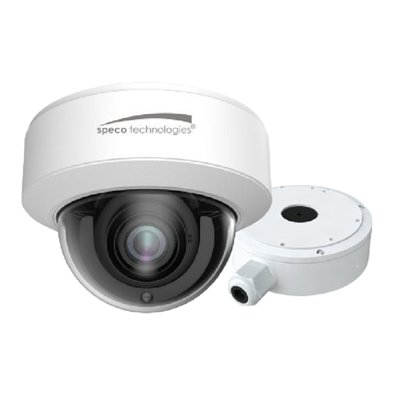
4MP IP Camera
O4B7MN/O4D6N/ O4D7MN/ O4T7N/ O4T7MN / O4P4N/O4B6N
Please read this manual carefully before operating the unit and keep it for further reference
Table of
Contents
Previous
Page
Next
Page
1
2
3
4
5
Advertisement
Table of Contents
Need help?
Do you have a question about the O4B7MN and is the answer not in the manual?
Ask a question
Questions and answers
Subscribe to Our Youtube Channel
Related Manuals for Speco O4B7MN
Security Camera Speco O4D6 User Manual
4mp ip camera (57 pages)
Security Camera Speco O4B6N Quick Start Manual
(9 pages)
Security Camera Speco O4D6N Quick Start Manual
(9 pages)
Security Camera Speco O4B6M Quick Start Manual
(7 pages)
Security Camera Speco O4P4 User Manual
(57 pages)
Security Camera Speco O4B6 Quick Start Manual
(8 pages)
Security Camera Speco O4B7M Quick Start Manual
(9 pages)
Security Camera Speco Deterrent O4BDD1M User Manual
4mp digital ip camera (54 pages)
Security Camera Speco O4BDD1M Quick Start Manual
(9 pages)
Security Camera Speco O4B7 Quick Start Manual
4mp fixed lens bullet ip camera (10 pages)
Security Camera Speco O4B9M User Manual
4mp ip camera (59 pages)
Security Camera Speco O4B9M Quick Start Manual
(9 pages)
Security Camera Speco O4B9 Quick Start Manual
(9 pages)
Security Camera Speco O4BLP2M Quick Start Manual
(11 pages)
Security Camera Speco O4DM User Manual
4mp ip camera (69 pages)
Security Camera Speco O4BXLP1M User Manual
4mp white light license plate recognition ip camera (51 pages)
This manual is also suitable for:
O4d6n
O4d7mn
O4t7n
O4t7mn
O4p4n
O4b6n
Table of Contents
Print
Rename the bookmark
Delete bookmark?
Delete from my manuals?
Login
Sign In
OR
Sign in with Facebook
Sign in with Google
Upload manual
Upload from disk
Upload from URL


Need help?
Do you have a question about the O4B7MN and is the answer not in the manual?
Questions and answers