
Subscribe to Our Youtube Channel
Related Manuals for Speco Deterrent O4BDD1M


Summary of Contents for Speco Deterrent O4BDD1M
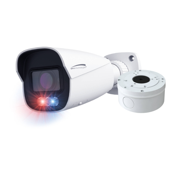
- Page 1 User Manual 4MP Digital Deterrent® IP Camera O4BDD1M/ O4TDD1M Please read this manual carefully before operating the unit and keep it for further reference...
- Page 2 Important Safeguards and Warnings 1. Electrical safety All installation and operation here should conform to local electrical safety codes. Use a certified/listed 12VDC Class2 power supply only. Please note: Do not connect two power supplying sources to the device at the same time; it may result in device damage! The product must be grounded to reduce the risk of electric shock.
- Page 3 Statement This guide is for reference only. Product, manuals, and specifications may be modified without prior notice. Speco Technologies reserves the right to modify these without notice and without incurring any obligation. Speco Technologies is not liable for any loss caused by improper operation.
-
Page 4: Table Of Contents
Table of Contents Introduction ..........................................2 Web Access and Login ......................................3 Live View..........................................5 Camera Configuration ......................................7 System Configuration ................................7 4.1.1 System Information ..............................7 4.1.2 Date and Time ................................7 4.1.3 Local Recording ................................8 4.1.4 Storage .................................. - Page 5 7.3.4 Security Management...............................40 Maintenance Configuration ..............................41 7.4.1 Backup and Restore ..............................41 7.4.2 Reboot ..................................41 7.4.3 Upgrade ..................................41 7.4.4 Operation Log ................................42 Search ............................................ 43 Image Search ..................................43 Video Search ..................................45 8.2.1 Local Video Search ..............................45 8.2.2 SD Card Video Search..............................46 Appendix ............................................
-
Page 6: Introduction
Thank you for purchasing this network camera! Please read this manual carefully before operating the unit and retain it for further reference. Should you require any technical assistance, please contact Speco Technologies Technical Support at 1-800-645-5516. Main Features ⚫ Built-in PoE (Power over Ethernet) ⚫... -
Page 7: Web Access And Login
2 Web Access and Login The IP camera settings can be accessed via a web browser through the LAN. Available web browser: IE (plug-in required)/ Firefox/Edge/Safari/Google Chrome It is recommended to use the latest version of these web browsers. The menu display and operation of the camera may be slightly different by using the browser with plug-in or without plug-in. Installing plug-in will display more functions of the camera. - Page 8 The login interface is shown above. Default username is admin and the password is 1234. After logging in, follow directions to install applicable plug-ins for viewing video if prompted. If this is the first time for you to log in, the password prompt may only change the admin password. By default, the ONVIF password will match the admin password that you set.
-
Page 9: Live View
3 Live View The window below will be shown after logging in. The following table describes the icons on the live view interface Icon Description Icon Description Original size of resolution Rule information display Fit (correct scale) SD card recording indicator Auto (fill the window) Abnormal color indicator Full screen (show video only) - Page 10 *Plug-in free live view: PTZ control, two-way audio and local recording are not supported. ⚫ All indicator icons above will flash in live view interface only when the corresponding events are enabled. ⚫ In full screen mode, to exit, double click on the mouse or press the ESC key on the keyboard. Click the zoom/focus control button to show the control panel.
-
Page 11: Camera Configuration
4 Camera Configuration Press the “Setup” button to go to the configuration interface. Note: Wherever applicable, click the “Save” button to save the settings. 4.1 System Configuration 4.1.1 System Information In the “System Information” interface, the system information of the device is listed. 4.1.2 Date and Time To set the time and date, go to System→Date and Time. -
Page 12: Local Recording
4.1.3 Local Recording Go to System→Local Recording to set up the storage path of captured pictures and recorded videos on the local PC. There is also an option to enable or disable the bitrate display in the recorded files. Additionally, the snapshots triggered by smart events (like line crossing detection, intrusion detection, etc.) can be selected to save to the local PC. - Page 13 ⚫ Schedule Recording Settings 1. Go to Storage→Record to go to the interface as shown below. 2. Set record stream, pre-record time and cycle writing. Pre Record Time: Set the time to record before the actual recording begins. 3. Set schedule recording. Check “Enable Schedule Record” and set the schedule. Weekly schedule Set the alarm time from Monday to Sunday for a single week.
-
Page 14: Video Configuration
Day schedule Set the alarm time for alarm a special day, such as a holiday. Note: Holiday schedule takes priority over weekly schedule. ⚫ Snapshot Settings Go to System→Storage→Snapshot to go to the interface as shown below. Set the format, resolution and quality of the image saved on the SD card and the snapshot interval and quantity and the timing snapshot here. - Page 15 Brightness: Set the brightness level of the camera’s image. Contrast: Set the color difference between the brightest and darkest parts. Hue: Set the total color degree of the image. Saturation: Set the degree of color purity. The purer the color, the brighter the image is. Sharpness: Set the resolution level of the image plane and the sharpness level of the image edge.
-
Page 16: Video / Audio Configuration
higher the level is, the more overexposure compensation will be given. White Balance: Adjust the color temperature according to the environment automatically. Day/Night Mode: Choose “Auto”, “Day”, “Night” or “Timing”. Exposure Mode: Choose “Auto” or “Manual”. If manual is chosen, the digital shutter speed can be adjusted. Gain Mode: Choose “Auto”... - Page 17 Three video streams can be adjustable. Resolution: The size of image. Frame rate: The higher the frame rate, the video is smoother. Bitrate type: CBR and VBR are optional. Bitrate is related to image quality. CBR means that no matter how much change is seen in the video scene, the compression bitrate will be kept constant.
-
Page 18: Osd Configuration
Please set LIN/MIC IN Volume and audio out volume as needed. 4.2.3 OSD Configuration Go to Video→OSD interface as shown below. Set time stamp, device name, OSD content and picture overlap here. After enabling the corresponding display and entering the content, drag them to change their position. -
Page 19: Roi Configuration
To clear the video mask: Click the “Clear” button to delete the current video mask area. 4.2.5 ROI Configuration Go to Image→ROI Config interface as shown below. An area in the image can be set as a region of interest. This area will have a higher bitrate than the rest of the image, resulting in better image quality for the identified area. -
Page 20: Event Setup
4.3 Event Setup 4.3.1 Motion Detection Go to Alarm→Motion Detection to set motion detection alarm. 1. Check “Enable” check box to activate motion-based alarms. If unchecked, the camera will not send out any signals to trigger motion-based recording to the NVR or CMS, even if there is motion in the video. Alarm Out: If selected, this would trigger an external relay output that is connected to the camera on detecting a motion-based alarm. -
Page 21: Other Alarms
interface), the captured pictures and triggered event will be sent into those addresses. Trigger FTP: If “Trigger FTP” and “Attach Picture” are checked, the captured pictures will be sent into FTP server address. Please refer to FTP configuration chapter for more details. Note: There is no light alarm setting for motion as the light will cast continuous motion to the scene. - Page 22 2. Click “Enable” and set the alarm holding time. 3. Set alarm trigger options. Trigger alarm out, Email and FTP. The setup steps are the same as motion detection. Please refer to motion detection section for details. ⚫ IP Address Conflict This function is only available for the models with Alarm Out interface.
-
Page 23: Alarm In (Sensor Input)
4.3.3 Alarm In (Sensor Input) This function is only available for some models. To set sensor alarm (alarm in): Go to Alarm→Alarm In interface as shown below. 1. Click “Enable” and set the alarm type, alarm holding time and sensor name. 2. -
Page 24: Alarm Server
Alarm Out Mode: Alarm linkage, manual operation, day/night switch linkage and schedule are optional. Alarm Linkage: Having selected this mode, select alarm out name, alarm holding time at the “Alarm Holding Time” pull down list box and alarm type. Manual Operation: Having selected this mode, select alarm type and click “Open” to trigger the alarm out immediately; click “Close” to stop alarm. -
Page 25: Audio Alarm
4.3.6 Audio Alarm 1. Go to Alarm→Audio Alarm interface as shown below. 2. Select the warning voice. If you want to customize the voice, you can choose “Customize”. Click “Browse” to choose the audio file you want to upload and then enter the audio name. Finally, click “Upload” to upload the audio file. Note that the format of the audio file must meet the requirement (see Tips), or it will not be uploaded. -
Page 26: Light Alarm
⚫ Set the record audio volume and then click “Start” to start recording your voice. ⚫ Click “Upload” to upload your customized voice. 3. Select the voice and then set the warning times and volume as needed. Warning times: it ranges from 1 to 50. Click “OK”... - Page 27 1. Enable the applicable detection that is desired. Scene Change Detection: Alarms will be triggered if the scene of the video has changed. Video Blur Detection: Alarms will be triggered if the video becomes blurry. Video Cast Detection: Alarms will be triggered if the video becomes obscured. 2.
-
Page 28: Line Crossing
7.1.2 Line Crossing Line Crossing: Alarms will be triggered if the target crosses the defined alarm lines. Go to Event→Line Crossing interface as shown below. 1. Enable line crossing alarm and select the snapshot type and the detection target. Save Panoramic Picture To SD Card: If it is enabled, the detected panoramic pictures will be captured and saved to the SD card when there are targets detected. -
Page 29: Intrusion
Set the alarm line number and direction. Up to 4 lines can be added. Multiple lines cannot be added simultaneously. Direction:A<->B, A->B and A<-B optional. This indicates the direction of the intruder who crosses over the alarm line that would trigger the alarm. - Page 30 1. Enable intrusion alarm and select the snapshot type and the detection target. 2. Set the alarm holding time. 3. Set alarm trigger options. The setup steps are the same as sensor alarm. Please refer to Alarm IN chapter for details. 4.
-
Page 31: Region Entrance
area. Click the “Save” button to save the settings. 6. Set the schedule of the intrusion detection. The setup steps of the schedule are the same as schedule recording setup (See Schedule Recording). ※Configuration requirements of camera and surrounding area 1. -
Page 32: Region Exiting
Set the alarm area number on the right side. Up to 4 alarm areas can be added. Click the “Draw Area” button and then click around the area where you want to set as the alarm area in the image on the left side (the alarm area should be a closed area). - Page 33 1. Enable region exiting detection and select the snapshot type and the detection target. 2. Set the alarm holding time. 3. Set alarm trigger options. The setup steps are the same as sensor alarm. Please refer to Alarm IN chapter for details. 4.
-
Page 34: Network Configuration
(the alarm area should be a closed area). Click the “Stop Draw” button to stop drawing. Click the “Clear” button to delete the alarm area. Click the “Save” button to save the settings. 6. Set the schedule of the region exiting detection. The setup steps of the schedule are the same as schedule recording setup (See Schedule Recording). -
Page 35: Port
Trigger Email: when the IP address of the device is changed, the new IP address will be sent to the email address that has been set Trigger FTP: when the IP address of the device is changed, the new IP address will be sent to FTP server that has been set up. 7.2.2 Port Go to Network→Port interface as shown below. -
Page 36: Ddns
Note: when adding the device to the third-party platform with ONVIF/RTSP protocol, please enter the username and password created in the above interface. 7.2.5 DDNS If the camera is set up with a DHCP connection, DDNS should be set for accessing the camera from the internet. 1. -
Page 37: 802.1X
2. Check the corresponding version checkbox (Enable SNMPv1, Enable SNMPv2, Enable SNMPv3) according to the version of the SNMP software that will be used. 3. Set the values for “Read SNMP Community”, “Write SNMP Community”, “Trap Address”, “Trap Port” and so on. Please make sure the settings are the same as that of the SNMP software. -
Page 38: Rtsp
authentication system to identify the device in a local network. If the camera connected to the network interface of the switch has passed the authentication of the switch, it can be accessed via the local network. Protocol type and EAPOL version: Please use the default settings. User name and password: The user name and password must be the same with the user name and password applied for and registered in the authentication server. -
Page 39: Upnp
Check “Enable”, select stream type, set the reconnection time after timeout and server address as needed. Server address: Enter the server address allocated by the third party server. After that, click “Save” to save the settings. Then click “Refresh” to view the connection status. 7.2.10 UPNP If this function is enabled, the camera can be quickly accessed through the LAN. -
Page 40: Https
Server Name: The name of the FTP server. Server Address: The IP address or domain name of the FTP. Upload Path: The directory where files will be uploaded to. Port: The port of the FTP server. Use Name and Password: The username and password that are used to login to the FTP server. 7.2.13 HTTPS HTTPs provides authentication of the web site and protects user privacy. -
Page 41: Qos
Click the “Create” button to create a private certificate. Enter the country (only two letters available), domain (camera’s IP address/domain), validity date, password, province/state, region and so on. Then click “OK” to save the settings. * Click “Create a certificate request” to enter the following interface. Click “Create”... - Page 42 Add user: 1. Click “Add” to pop up the following textbox. 2. Enter user name in “User Name” textbox. 3. Enter letters or numbers in “Password” and “Confirm Password” textbox. Please set the password according to the requirement of the password security level (Go to Setup→Security→Security Management→Password Security interface to set the security level). 4.
-
Page 43: Online User
3. Enter the old password of the user in the “Old Password” text box. 4. Enter the new password in the “New password” and “Confirm Password” text box. 5. Modify the permission as necessary. 6. Click the “OK” button to save the settings. Note: To change the access level of a user, the user must be deleted and added again with the new access level. -
Page 44: Security Management
The setup steps are as follows: Check the “Enable address filtering” check box. Select “Block/Allow the following address”, IPv4/IPv6 and then enter IP address in the address box and click the “Add” button. 7.3.4 Security Management Go to Security→Security Management as shown below. In order to prevent against malicious password unlocking, “locking once illegal login”... -
Page 45: Maintenance Configuration
7.4 Maintenance Configuration 7.4.1 Backup and Restore Go to Maintenance→Backup & Restore. Import & Export Settings ⚫ Configuration settings of the camera can be exported form a camera into another camera. 1. Click “Browse” to select the save path for import or export information on the PC. 2. -
Page 46: Operation Log
2. Click the “Upgrade” button to start upgrading the firmware. 3. Enter the correct password and then the device will restart automatically Caution! Do not close the browser or disconnect the camera from the network during the upgrade. 7.4.4 Operation Log To query and export log: 1. -
Page 47: Search
8 Search 8.1 Image Search In the Setup interface, click Search to go to the interface as shown below. Images that are saved on the PC or SD card can be found here. ⚫ Local Image Search 1. Choose “Picture”—“Local”. 2. - Page 48 Click to return to the previous interface. ⚫ SD Card Image Search 1. Choose “Picture”—“SD Card”. 2. Set time: Select date and choose the start and end time. 3. Choose the alarm events at the bottom of the interface. 4. Click to search the images.
-
Page 49: Video Search
Icon Description Icon Description Close: Select an image and click Close all: Click this button to close all this button to close the image. images. Save: Click this button to select the Save all: Click this button to select the path for saving the image on the path for saving all pictures on the PC. -
Page 50: Sd Card Video Search
Icon Description Icon Description Play button. After pausing the video, Pause button click this button to continue playing. Stop button Speed down Speed up Watermark display Enable / disable audio; drag the slider to adjust the volume after enabling audio. 8.2.2 SD Card Video Search Click Search to go to the interface as shown below. - Page 51 4. Select the alarm events at the bottom of the interface. 5. Select mix stream (video and audio stream) or video stream as needed. 6. Double click on a file name in the list to start playback. The time table can be shown in 24H/12H/2H/1H format by clicking the corresponding buttons. Video clip and downloading 1.
- Page 52 Click “Set up” to set the storage directory of the video files. Click “Open” to play the video. Click “Clear List” to clear the downloading list. Click “Close” to close the downloading window.
-
Page 53: Appendix
Appendix Appendix 1 Troubleshooting IP Scanner does not show any device. Make sure that the PC that’s running IP Scanner is on the same local network as the devices. Internet Explorer cannot download ActiveX control. IE browser may be set up to block ActiveX. Follow the steps below. 1. - Page 54 This device complies with Part 15 of the FCC Rules. Operation is subject to the following two conditions: (1) This device may not cause harmful interference, and (2) This device must accept any interference received, including interference that may cause undesired operation. FCC Responsible Party: Speco Technologies 200 New Highway Amityville, NY11701...
Need help?
Do you have a question about the Deterrent O4BDD1M and is the answer not in the manual?
Questions and answers