Table of Contents
Advertisement
Quick Links
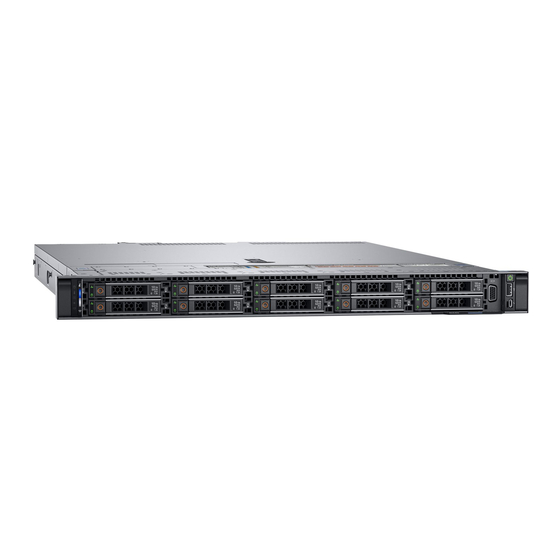
Dell EMC PowerEdge R440
Installation and Service Manual
Regulatory Model: E45S Series
Regulatory Type: E45S001
December 2021
Rev. A17
Questo manuale d'istruzione è fornito da trovaprezzi.it. Scopri tutte le offerte per
R440 PER4402A
o cerca il tuo prodotto tra le
migliori offerte di Server
Dell PowerEdge
Advertisement
Table of Contents

Related Manuals for Dell PER4402A


Summary of Contents for Dell PER4402A
- Page 1 Questo manuale d’istruzione è fornito da trovaprezzi.it. Scopri tutte le offerte per Dell PowerEdge R440 PER4402A o cerca il tuo prodotto tra le migliori offerte di Server Dell EMC PowerEdge R440 Installation and Service Manual Regulatory Model: E45S Series Regulatory Type: E45S001 December 2021...
- Page 2 A WARNING indicates a potential for property damage, personal injury, or death. © 2017 - 2021 Dell Inc. or its subsidiaries. All rights reserved. Dell, EMC, and other trademarks are trademarks of Dell Inc. or its subsidiaries. Other trademarks may be trademarks of their respective owners.
-
Page 3: Table Of Contents
Contents Chapter 1: Dell EMC PowerEdge R440 system overview..............7 Front view of the system..............................7 Left control panel view............................... 10 Right control panel view............................. 12 Drive indicator codes..............................14 Back view of the system..............................15 NIC indicator codes..............................17 Power supply unit indicator codes........................... 17 LCD panel.....................................18... - Page 4 Installing cooling fan..............................36 Intrusion switch..................................37 Removing the intrusion switch..........................37 Installing the intrusion switch........................... 38 Drives....................................39 Removing a drive blank.............................. 39 Installing a drive blank..............................39 Removing a 2.5-inch drive from a 3.5-inch drive adapter................40 Installing a 2.5-inch drive into a 3.5-inch drive adapter..................41 Removing a 3.5-inch drive adapter from a 3.5-inch drive carrier..............
- Page 5 Chapter 5: System diagnostics....................115 Dell Embedded System Diagnostics..........................115 Running the Embedded System Diagnostics from Boot Manager..............115 Running the Embedded System Diagnostics from the Dell Lifecycle Controller........115 System diagnostic controls............................115 Chapter 6: Getting help......................117 Contacting Dell EMC............................... 117...
- Page 6 Documentation feedback..............................117 Accessing system information by using QRL......................117 Quick Resource Locator for Dell EMC PowerEdge R440 system..............118 Receiving automated support with SupportAssist ....................118 Recycling or End-of-Life service information......................118 Chapter 7: Documentation resources..................119 Contents...
-
Page 7: Chapter 1: Dell Emc Poweredge R440 System Overview
Dell EMC PowerEdge R440 system overview The Dell EMC PowerEdge R440 system is a 1U, dual socket rack system supports up to: ● Two Intel Xeon Scalable Processors ● 16 DIMM slots ● 4 x 3.5-inch drives, 8 x 2.5-inch drives, or 10 x 2.5-inch drives ●... - Page 8 One optional slim SATA DVD-ROM drive or DVD+/-RW drive. VGA port Enables you to connect a display device to the system. For more information, see the Dell EMC PowerEdge R440 Technical Specifications on the product documentation page. Right control panel Contains the power button, USB port, iDRAC Direct micro port, and the iDRAC Direct status LED.
- Page 9 Enables you to connect a display device to the system. Right control panel Contains the power button, USB port, iDRAC Direct micro port, and the iDRAC Direct status LED. see the Dell EMC PowerEdge R440 Technical Specifications on the product documentation page.
-
Page 10: Left Control Panel View
NOTE: iDRAC Quick information that can be used in troubleshooting the system. Sync 2 wireless You can access system inventory, Dell Lifecycle Controller indicator is available logs or system logs, system health status, and also configure only on certain iDRAC, BIOS, and networking parameters. You can also launch configurations. - Page 11 System Event Log or the LCD panel, if available on the bezel, for specific error messages. For more information about error messages, see the Event and Error Message Reference Guide for 14th Generation Dell EMC PowerEdge Servers at www.dell.com/qrl. iDRAC Quick Sync 2 indicator codes iDRAC Quick Sync 2 module (optional) is located on the left control panel of your system.
-
Page 12: Right Control Panel View
If the problem persists, see the Getting help section. For more information, see Integrated Dell Remote Access Controller User's Guide at www.dell.com/ poweredgemanuals or Dell OpenManage Server Administrator User’s Guide at www.dell.com/... - Page 13 Solid green for two seconds Flashing green (on for Indicates that the laptop or tablet connected is recognized. two seconds and off for two seconds) Turns off Indicates that the laptop or tablet is unplugged. Dell EMC PowerEdge R440 system overview...
-
Page 14: Drive Indicator Codes
Flashes amber four times per second Drive failed. Flashes green slowly Drive rebuilding. Solid green Drive online. Flashes green for three seconds, amber for three Rebuild stopped. seconds, and then turns off after six seconds Dell EMC PowerEdge R440 system overview... -
Page 15: Back View Of The System
Use the iDRAC9 dedicated network port to securely access network port the embedded iDRAC on a separate management network, see the Integrated Dell Remote Access Controller User's Guide at www.dell.com/poweredgemanuals Ethernet ports (2) Use the Ethernet ports to connect Local Area Networks (LANs) to the system. - Page 16 Use the iDRAC9 dedicated network port to securely access network port the embedded iDRAC on a separate management network, see the Integrated Dell Remote Access Controller User's Guide at www.dell.com/poweredgemanuals Ethernet ports (2) Use the Ethernet ports to connect Local Area Networks (LANs) to the system.
-
Page 17: Nic Indicator Codes
AC power supply units (PSUs) have an illuminated translucent handle that serves as an indicator. The indicator shows whether power is present or if a power fault has occurred. Figure 12. AC PSU status indicator 1. AC PSU status indicator/handle Dell EMC PowerEdge R440 system overview... -
Page 18: Lcd Panel
● If the LCD panel stops responding, remove the bezel and reinstall it. If the problem persists, see the PowerEdge T640 Technical Specs at www.dell.com/poweredgemanuals ● The LCD backlight remains off if LCD messaging is turned off using the iDRAC utility, the LCD panel, or other tools. Figure 13. LCD panel features Dell EMC PowerEdge R440 system overview... -
Page 19: Viewing Home Screen
Home screen. View menu NOTE: When you select an option in the View menu, you must confirm the option before proceeding to the next action. Dell EMC PowerEdge R440 system overview... -
Page 20: Locating The Service Tag Of Your System
Express Service Code and Service Tag. Alternatively, the information may be on a sticker on the chassis of the system. The mini Enterprise Service Tag (EST) is found on the back of the system. This information is used by Dell to route support calls to the appropriate personnel. -
Page 21: System Label Information
System Label Information Service and Memory Information Label Figure 15. Service and memory information label Dell EMC PowerEdge R440 system overview... -
Page 22: Chapter 2: Initial System Setup And Configuration
For more information about setting up your system, see the Getting Started Guide that shipped with your system. For information on how to manage basic settings and features of the system, see the Dell EMC PowerEdge R440 BIOS and UEFI Reference Guide on the product documentation page. -
Page 23: Log In To Idrac
Ensure that you change the default username and password after setting up the iDRAC IP address. For more information about logging in to the iDRAC and iDRAC licenses, see the latest Integrated Dell Remote Access Controller User's Guide at www.dell.com/poweredgemanuals. -
Page 24: Downloading Drivers And Firmware
Using iDRAC virtual media www.dell.com/idracmanuals Downloading drivers and firmware Dell EMC recommends that you download and install the latest BIOS, drivers, and systems management firmware on your system. Prerequisites Ensure that you clear the web browser cache before downloading the drivers and firmware. -
Page 25: Chapter 3: Installing And Removing System Components
Damage due to servicing that is not authorized by Dell is not covered by your warranty. Read and follow the safety instructions that are shipped with your product. -
Page 26: Before Working Inside Your System
NOTE: It is recommended that you always use an antistatic mat and antistatic strap while working on components inside the system. CAUTION: To ensure proper operation and cooling, all bays in the system and system fans must be always populated with a component or a blank. Before working inside your system Prerequisites Follow the safety guidelines listed in... -
Page 27: Installing The Front Bezel
Steps 1. Unlock the bezel by using the bezel key. 2. Press the release button, and pull the left end of the bezel. 3. Unhook the right end, and remove the bezel. Figure 16. Removing the front bezel with the LCD panel Installing the front bezel The procedure to install the front bezel with and without the LCD panel is the same. -
Page 28: System Cover
Figure 17. Installing the front bezel with the LCD panel System cover Removing the system cover Prerequisites 1. Follow the safety guidelines listed in Safety instructions. 2. Turn off the system, including any attached peripherals. 3. Disconnect the system from the electrical outlet and disconnect the peripherals. Steps 1. -
Page 29: Installing The System Cover
Figure 18. Removing the system cover Installing the system cover Prerequisites 1. Follow the safety guidelines listed in Safety instructions. 2. Ensure that all internal cables are routed correctly and connected, and no tools or extra parts are left inside the system. Steps 1. -
Page 30: Inside The System
Damage due to servicing that is not authorized by Dell is not covered by your warranty. Read and follow the safety instructions that are shipped with your product. -
Page 31: Backplane Cover
Figure 20. Inside the system 1. left control panel cable cover 2. hard drive backplane 3. backplane expander board 4. cabling latch 5. air shroud 6. intrusion switch 7. power interposer board 8. internal expansion riser 9. low profile expansion riser 1 10. -
Page 32: Installing The Backplane Cover
Figure 21. Removing backplane cover Installing the backplane cover Prerequisites 1. Follow the safety guidelines listed in Safety instructions. 2. Follow the procedure listed in Before working inside your system. Install the system cover. Steps 1. Align the tabs on the backplane cover with the guide slots on the system. 2. - Page 33 Figure 22. Installing backplane cover Next steps Follow the procedure listed in After working inside your system. Installing and removing system components...
-
Page 34: Air Shroud
Air shroud Removing the air shroud Prerequisites CAUTION: Never operate your system with the air shroud removed. The system may get overheated quickly, resulting in shutdown of the system and loss of data. 1. Follow the safety guidelines listed in Safety instructions. -
Page 35: Cooling Fans
2. Lower the air shroud into the system until it is firmly seated. When firmly seated, the memory socket numbers marked on the air shroud align with the respective memory sockets. Figure 24. Installing the air shroud Next steps 1. Follow the procedure listed in After working inside your system. -
Page 36: Installing Cooling Fan
Figure 25. Removing the cooling fan 2. Lift the fan out holding the blue touch point. Next steps Install the cooling fan. Install the internal riser. 3. Connect the power cable to the system board. 4. Ensure the cables are routed correctly. Install the air shroud. -
Page 37: Intrusion Switch
Figure 26. Installing cooling fan Next steps Install the internal riser. 2. Connect the power cable. 3. Ensure all the cables are routed correctly. Install the air shroud. 5. Follow the procedure listed in After working inside your system. Intrusion switch Removing the intrusion switch Prerequisites 1. -
Page 38: Installing The Intrusion Switch
Figure 27. Removing an intrusion switch Next steps Install intrusion switch. Installing the intrusion switch Prerequisites 1. Follow the safety guidelines listed in Safety instructions. 2. Follow the procedure listed in Before working inside your system. Steps 1. Align the intrusion switch with the intrusion switch slot. Figure 28. -
Page 39: Drives
Drives Removing a drive blank The procedure for removing 2.5-inch and 3.5-inch drive blanks is identical. Prerequisites 1. Follow the safety guidelines listed in Safety instructions. 2. If installed, remove the front bezel. CAUTION: To maintain proper system cooling, drive blanks must be installed in all empty drive slots. CAUTION: Mixing drive blanks from previous generations of PowerEdge servers is not supported. -
Page 40: Removing A 2.5-Inch Drive From A 3.5-Inch Drive Adapter
Figure 30. Installing a drive blank Next steps If removed, install the front bezel. Removing a 2.5-inch drive from a 3.5-inch drive adapter Prerequisites 1. Follow the safety guidelines listed in Safety instructions. Remove the 3.5-inch drive adapter from the 3.5-inch drive carrier. NOTE: A 2.5-inch drive is installed in a 3.5-inch drive adapter, which is then installed in the 3.5-inch drive carrier. -
Page 41: Installing A 2.5-Inch Drive Into A 3.5-Inch Drive Adapter
Next steps Install a 2.5-inch drive into a 3.5-inch drive adapter. Installing a 2.5-inch drive into a 3.5-inch drive adapter Prerequisites 1. Follow the safety guidelines listed in Safety instructions. Remove the 3.5-inch drive adapter from the 3.5-inch hot swappable drive carrier. Steps 1. -
Page 42: Installing A 3.5-Inch Drive Adapter Into The 3.5-Inch Drive Carrier
Figure 33. Removing a 3.5 inch drive adapter from a 3.5-inch drive carrier Next steps Install the 3.5-inch drive carrier -inch Installing a 3.5-inch drive adapter into the 3.5-inch drive carrier Prerequisites 1. Follow the safety guidelines listed in Safety instructions. -
Page 43: Removing A Hard Drive
Figure 34. Installing a 3.5-inch drive adapter into the 3.5-inch drive carrier Next steps 1. Install the 3.5-inch drive carrier into the system. 2. If removed, install the front bezel. Removing a hard drive Prerequisites 1. Follow the safety guidelines listed in Safety instructions. -
Page 44: Installing A Hard Drive
Figure 35. Removing a hard drive Next steps Install a hard drive. 2. If you are not replacing the hard drive immediately, insert a hard drive blank in the empty hard drive slot to maintain proper system cooling. Installing a hard drive Prerequisites CAUTION: Before attempting to remove or install a hard drive while the system is running, see the... -
Page 45: Removing The Drive From The Drive Carrier
Figure 36. Installing a hard drive Next steps If applicable, install the front bezel. Removing the drive from the drive carrier Prerequisites CAUTION: Mixing drives from previous generations of PowerEdge servers is not supported. Steps 1. Using a Phillips #1 screwdriver, remove the screws from the slide rails on the drive carrier. 2. -
Page 46: Installing A Drive Into The Drive Carrier
Next steps If applicable, install the drive into the drive carrier. Installing a drive into the drive carrier Prerequisites CAUTION: Mixing drive carriers from other generations of PowerEdge servers is not supported. NOTE: When installing a drive into the drive carrier, ensure that the screws are torqued to 4 in-lbs. Steps 1. - Page 47 Figure 39. Memory socket locations Memory channels are organized as follows: Table 18. Memory channels Processor Channel 0 Channel 1 Channel 2 Channel 3 Channel 4 Channel 5 Processor 1 Slots A1 and A7 Slots A2 and Slots A3 Slots A4 and A9 Slots A5 and A10 Slots A6 Processor 2 Slots B1...
-
Page 48: General Memory Module Installation Guidelines
General memory module installation guidelines To ensure optimal performance of your system, observe the following general guidelines when configuring your system memory. If your system's memory configurations fail to observe these guidelines, your system might not boot, stop responding during memory configuration, or operate with reduced memory. - Page 49 Dell Fault Resilient Mode The Dell Fault Resilient Mode if enabled, the BIOS creates an area of memory that is fault resilient. This mode can be used by an OS that supports the feature to load critical applications or enables the OS kernel to maximize system availability.
- Page 50 Table 21. Memory population rules (continued) Processor Configuration Memory population Memory population information NOTE: Odd number of DIMMs will result in unbalanced memory configurations, which in turn will result in performance loss. It is recommended to populate all memory channels identically with identical DIMMs for best performance.
-
Page 51: Removing A Memory Module
Table 21. Memory population rules (continued) Processor Configuration Memory population Memory population information Single rank sparing population A{1}, B{1}, A{2}, B{2}, A{3}, Populate in this order, odd amount order B{3}... per processor allowed. Requires two ranks or more per channel. Multi rank sparing population A{1}, B{1}, A{2}, B{2}, A{3}, Populate in this order, odd amount... -
Page 52: Processors And Heat Sinks
CAUTION: Handle each memory module only by the card edges, ensuring not to touch the middle of the memory module or metallic contacts. CAUTION: To prevent damage to the memory module or the memory module socket during installation, do not bend or flex the memory module. You must insert both ends of the memory module simultaneously. 2. -
Page 53: Installing A Processor And Heat Sink Module
2. Follow the procedure listed in Before working inside your system. 3. If applicable, remove the air shroud. Steps 1. Using a Torx #T30 screwdriver, loosen the screws on the heat sink in the order below: a. Loosen the first screw three turns. b. -
Page 54: Removing The Processor From The Processor And Heat Sink Module
CAUTION: To avoid damaging the fins on the heat sink, do not press down on the heat sink fins. NOTE: Ensure that the PHM is held parallel to the system board to prevent damaging the components. 2. Push the blue retention clips inward to allow the heat sink to drop into place. 3. -
Page 55: Installing The Processor Into A Processor And Heat Sink Module
2. Follow the procedure listed in Before working inside your system. remove the air shroud. Remove the processor and heat sink module. Steps 1. Place the heat sink with the processor side facing up. 2. Insert a flat blade screwdriver into the release slot marked with a yellow label. Twist (do not pry) the screwdriver to break the thermal paste seal. - Page 56 Figure 45. Installing the processor bracket 3. If you are using an existing heat sink, remove the thermal grease from the heat sink by using a clean lint-free cloth. 4. Use the thermal grease syringe included with your processor kit to apply the grease in a quadrilateral design on the top of the processor.
-
Page 57: Internal Perc Riser
● Do not press on the heat sink fins. ● Ensure that the pin 1 indicator on the heat sink is aligned with the pin 1 indicator on the bracket before placing the heat sink onto the processor and bracket. Figure 47. -
Page 58: Installing The Internal Perc Riser
Figure 48. Removing internal PERC riser 5. Turn the internal riser so that the PERC card is facing up. 6. Press the cable connector and disconnect the cable that is connected to the internal PERC card. Figure 49. Disconnecting the cable from internal PERC card Next steps Install the air shroud. - Page 59 Steps 1. Connect the cable to the internal PERC card. Figure 50. Connecting the cable to internal PERC riser 2. Holding the blue touch points, align the slot on the internal PERC riser to the guide on the system board. 3.
-
Page 60: Removing The Perc Card From The Internal Perc Riser
Removing the PERC card from the internal PERC riser Prerequisites 1. Follow the safety guidelines listed in Safety instructions. 2. Follow the procedure listed in Before working inside your system. Remove the air shroud. Remove the internal PERC riser. Steps 1. -
Page 61: Expansion Cards And Expansion Card Risers
Figure 53. Installing PERC card into internal PERC riser Next steps Install the internal PERC riser. Install the air shroud. 3. Follow the procedure listed in After working inside your system. Expansion cards and expansion card risers NOTE: A System Event Log (SEL) event is logged if an expansion card riser is not supported or missing. It does not prevent your system from turning on. - Page 62 Integrated Slot Low Profile RAID - PERC9.14G/PERC10 (Internal)/ Integrated Slot Low Profile PERC11 (Dell) Non-RAID - PERC 11 (Internal) (Dell) Integrated Slot Low Profile 1 Gb NIC Foxconn Table 24. Riser configurations: FH (Full Height riser*1) Card Type Slot Priority Form Factor PERC9.14G (Foxconn)
- Page 63 HBA: External adapter (Dell) Low Profile RAID - PERC9.14G/PERC10 (Internal)/ Integrated Slot Low Profile PERC11 (Dell) Non-RAID - PERC 11 (Internal) (Dell) Integrated Slot Low Profile Non-RAID - PERC 11 (External) (Dell) Low Profile PERC 10 External adapter (Dell) Low Profile...
- Page 64 HBA: External adapter (Dell) 3, 2 Low Profile RAID - PERC9.14G/PERC10 (Internal)/ Integrated Slot Low Profile PERC11 (Dell) Non-RAID - PERC 11 (Internal) (Dell) Integrated Slot Low Profile Non-RAID - PERC 11 (External) (Dell) 3, 2 Low Profile PERC 10 External adapter (Dell)
- Page 65 Low Profile HBA: External adapter (Dell) Low Profile RAID - PERC9.14G/PERC10 (Internal)/ Low Profile PERC11 (Dell) Non-RAID - PERC 11 (Internal) (Dell) Low Profile Non-RAID - PERC 11 (External) (Dell) Low Profile PERC 10 External adapter (Dell) Low Profile RAID PERC10 (External) (Dell)
-
Page 66: Expansion Bus Specifications
Expansion bus specifications The PowerEdge R440 system supports PCI express (PCIe) generation three expansion cards, which must be installed on the system board using expansion card risers. The R440 system supports four types of expansion card risers. ● ○ LOM riser - One x8 PCIe Gen 3 for OCP form factor cards - connected to Processor1 ○... -
Page 67: Removing An Expansion Card Riser
Figure 55. Installing an expansion card riser 1 Figure 56. Installing an expansion card riser 2 Next steps 1. Follow the procedure listed in After working inside your system. 2. Install any device drivers required for the card as described in the documentation for the card. Removing an expansion card riser Prerequisites 1. - Page 68 Steps Hold the touch points, and lift the expansion card riser, from the riser connector, on the system board. Figure 57. Removing an expansion card riser 1A Figure 58. Removing an expansion card riser 1 Installing and removing system components...
-
Page 69: Removing The Expansion Card From The Expansion Card Riser
Figure 59. Removing an expansion card riser 2 Next steps Install the expansion card riser. Removing the expansion card from the expansion card riser Prerequisites 1. Follow the safety guidelines listed in Safety instructions. 2. Follow the procedure listed in Before working inside your system. - Page 70 Figure 60. Removing expansion card from riser 2 Figure 61. Removing expansion card from riser 1 3. Install a filler bracket if you are not replacing the expansion card. NOTE: You must install a filler bracket over an empty expansion card slot to maintain Federal Communications Commission (FCC) certification of the system.
- Page 71 Figure 62. Installing filler bracket for riser 2 Figure 63. Installing filler bracket for riser 1 Next steps Install the expansion card riser. Installing and removing system components...
-
Page 72: Installing The Expansion Card Into The Expansion Card Riser
Installing the expansion card into the expansion card riser Prerequisites 1. Follow the safety guidelines listed in Safety instructions. 2. If installing a new expansion card, unpack it and prepare the card for installation. NOTE: For instructions, see the documentation accompanying the card. 3. - Page 73 Figure 65. Removing filler bracket for riser 1 3. Hold the card by its edges, and align the card edge connector with the expansion card connector on the riser. 4. Insert the card edge connector firmly into the expansion card connector until the card is fully seated. 5.
-
Page 74: Internal Perc Riser
Figure 67. Installing expansion card into riser 1 Next steps 1. If applicable, connect the cables to the expansion card. 2. Install the expansion card riser 3. If applicable, install the air shroud. 4. Follow the procedure listed in After working inside your system. - Page 75 Figure 68. Removing internal PERC riser 5. Turn the internal riser so that the PERC card is facing up. 6. Press the cable connector and disconnect the cable that is connected to the internal PERC card. Figure 69. Disconnecting the cable from internal PERC card Next steps Install the air shroud.
- Page 76 Steps 1. Connect the cable to the internal PERC card. Figure 70. Connecting the cable to internal PERC riser 2. Holding the blue touch points, align the slot on the internal PERC riser to the guide on the system board. 3.
- Page 77 Removing the PERC card from the internal PERC riser Prerequisites 1. Follow the safety guidelines listed in Safety instructions. 2. Follow the procedure listed in Before working inside your system. Remove the air shroud. Remove the internal PERC riser. Steps 1.
-
Page 78: M.2 Ssd Module
Figure 73. Installing PERC card into internal PERC riser Next steps Install the internal PERC riser. Install the air shroud. 3. Follow the procedure listed in After working inside your system. M.2 SSD module NOTE: The write-protect switch is on the IDSDM or vFlash module. Installing the M.2 SSD module Prerequisites 1. -
Page 79: Removing The M.2 Ssd Module
Figure 74. Installing the M.2 SSD module Next steps 1. Install the BOSS card. NOTE: The procedure to install the BOSS card is similar to the removing an expansion card. Install the air shroud.. 3. Follow the procedure listed in After working inside your system. -
Page 80: Optional Microsd Or Vflash Card
Figure 75. Removing the M.2 SSD module Next steps Replace the M.2 SSD module. Optional MicroSD or vFlash card Removing the MicroSD card Prerequisites 1. Follow the safety guidelines listed in Safety instructions. 2. Follow the procedure listed in Before working inside your system. -
Page 81: Installing The Microsd Card
Figure 76. Removing the MicroSD card NOTE: Temporarily label each MicroSD card with its corresponding slot number after removal. Next steps 1. Follow the procedure listed in After working inside your system. Install a MicroSD card. Installing the MicroSD card Prerequisites Follow the safety guidelines listed in Safety... -
Page 82: Optional Idsdm Or Vflash Module
Figure 77. Installing the MicroSD card Next steps Follow the procedure listed in After working inside your system. Optional IDSDM or vFlash module Removing the optional IDSDM or vFlash card Prerequisites 1. Follow the safety guidelines listed in Safety instructions. 2. -
Page 83: Installing Optional Idsdm Or Vflash Card
Figure 78. Removing the optional IDSDM/vFlash card NOTE: There are two dip switches on the IDSDM/vFlash card for write-protection. Next steps Install the optional IDSDM/vFlash card. Installing optional IDSDM or vFlash card Prerequisites Follow the safety guidelines listed in Safety instructions Steps 1. -
Page 84: Lom Riser Card
Figure 79. Installing optional IDSDM/vFlash card Next steps Install the MicroSD cards. NOTE: Reinstall the MicroSD cards into the same slots based on the labels you had marked on the cards during removal. 2. Follow the procedure listed in After working inside your system LOM riser card Removing the LOM riser card Prerequisites... -
Page 85: Installing The Lom Riser Card
Figure 80. Removing LOM riser card Next steps Install the LOM riser card. Installing the LOM riser card Prerequisites Follow the safety guidelines listed in Safety instructions Steps 1. Align the connectors on the LOM riser card with the slot on the system. 2. -
Page 86: Hard Drive Backplane
2. Follow the procedure listed in After working inside your system Hard drive backplane Hard drive backplane details Depending on your system configuration, the hard drive backplanes supported in PowerEdge R440 are listed here: Table 29. Supported backplane options for PowerEdge R440 systems System Supported hard drives options 3.5-inch (x4) SAS, SATA backplane... -
Page 87: Installing The Hard Drive Backplane
Figure 85. 10 x 2.5 backplane with expander 1. SAS_A connector 2. backplane signal cable connector 3. backplane power cable connector 4. SAS_B connector 5. SAS_C connector Installing the hard drive backplane Prerequisites Follow the safety guidelines listed in Safety instructions. -
Page 88: Removing The Hard Drive Backplane
Next steps 1. Connect all the cables to the backplane. 2. Install all the hard drives. Install the backplane cover. Install the air shroud. 5. Follow the procedure listed in After working inside your system Removing the hard drive backplane Prerequisites CAUTION: To prevent damage to the drives and backplane, remove the hard drives from the system before... -
Page 89: Cable Routing
Next steps Install the hard drive backplane. Cable routing Figure 88. Cable routing - 10 x 2.5 hard drive backplane with PERC riser 1. Backplane 2. Backplane expander 3. Backplane power cable 4. Backplane signal cable 5. Backplane expander signal cable 6. - Page 90 Figure 89. Cable routing - 10 x 2.5 hard drive backplane with NVMe 1. Backplane 2. Backplane expander 3. Backplane power cable 4. Backplane power cable 5. Backplane expander signal cable 6. Cable routing clip 7. Power interposer board 8. Expansion card riser 9.
- Page 91 Figure 90. Cable routing - 8 x 2.5 hard drive backplane with PERC riser 1. Hard drive backplane 2. Backplane power cable 3. SAS cable (SAS_A and SAS_B cable connectors to internal 4. Backplane signal cable riser) 5. Cable routing clip 6.
- Page 92 5. backplane signal cable 6. cable routing clip 7. power interposer board 8. system board Figure 92. Cable routing - 4 x 3.5 hard drive backplane with PERC riser 1. hard drive backplane 2. backplane signal cable 3. cable routing clip 4.
-
Page 93: System Battery
5. backplane power cable 6. power supply unit 7. system board System battery The Dell EMC PowerEdge R440 system supports CR 2032 3.0-V lithium coin cell system battery. Replacing the system battery Prerequisites WARNING: There is a danger of a new battery exploding if it is incorrectly installed. Replace the battery only with the same or equivalent type recommended by the manufacturer. -
Page 94: Optional Internal Usb Memory Key
Figure 94. Removing the system battery 3. To install a new system battery, hold the battery with the positive side facing up and slide it under the securing tabs. 4. Press the battery into the connector until it snaps into place. Figure 95. -
Page 95: Optical Drive (Optional)
Next steps 1. Follow the procedure listed in After working inside your system. 2. While booting, press F2 to enter System Setup and verify that the system detects the USB memory key. Optical drive (optional) Removing the optical drive Prerequisites 1. -
Page 96: Power Supply Units
Power supply units NOTE: For more information, see the PowerEdge R440 Technical Specs at www.dell.com/poweredgemanuals. CAUTION: If two PSUs are installed, both the PSUs must have the same type of label. For example, Extended Power Performance (EPP) label. Mixing PSUs from previous generations of PowerEdge servers is not supported, even if the PSUs have the same power rating. -
Page 97: Installing A Power Supply Unit Blank
Figure 98. Removing a power supply unit blank Next steps Install the second power supply unit blank. Installing a power supply unit blank Prerequisites 1. Follow the safety guidelines listed in Safety instructions. NOTE: Install the power supply unit (PSU) blank only in the second PSU bay. Steps Align the PSU blank with the PSU slot and push it into the PSU slot until it clicks into place. -
Page 98: Installing A Power Supply Unit
For information about the cable management arm, see the system’s rack documentation at www.dell.com/ poweredgemanuals. Steps Press the release latch and slide the PSU out of the system by using the PSU handle. Figure 100. Removing a power supply unit Next steps Install the PSU. -
Page 99: Removing A Non-Redundant Cabled Ac Power Supply Unit
1. If you have unlatched the cable management arm, relatch it. For information about the cable management arm, see the system’s rack documentation at www.dell.com/poweredgemanuals. 2. Connect the power cable to the PSU, and plug the cable into a power outlet. -
Page 100: Installing A Non-Redundant Cabled Ac Power Supply Unit
Figure 102. Removing non-redundant cabled AC PSU Next steps Install a non-redundant cabled AC power supply. Installing a non-redundant cabled AC power supply unit Prerequisites 1. Follow the safety guidelines listed in Safety instructions. Steps 1. Unpack the new power supply unit (PSU). 2. -
Page 101: Power Interposer Board
Power interposer board Removing power interposer board Prerequisites 1. Follow the safety guidelines listed in Safety instructions. 2. Follow the procedure listed in Before working inside your system. Remove the air shroud 4. Disconnect all the cables connected from the PIB to the system board. NOTE: Ensure that you note the routing of the cables as you remove them from the system board. -
Page 102: Control Panel
Figure 105. Installing power interposer board Next steps Install the PSU. Install the air shroud. 3. Follow the procedure listed in After working inside your system. Control panel Removing the left control panel Prerequisites 1. Follow the safety guidelines listed in Safety instructions. -
Page 103: Installing The Left Control Panel
Figure 106. Removing the cable cover 3. Using a Phillips #1 screwdriver, remove the screws that connect the control panel to the system. Figure 107. Removing left control panel 4. Holding by the sides, remove the left control panel assembly away from the system. Next steps Install the left control panel. -
Page 104: Removing The Right Control Panel
Figure 108. Installing the cable cover Next steps 1. Follow the safety guidelines listed in Safety instructions. Install the air shroud. Install the internal PERC riser. 4. Follow the procedure listed in Before working inside your system. Removing the right control panel Prerequisites 1. -
Page 105: Installing The Right Control Panel
Figure 110. Removing right control panel 4. Holding the control panel by its sides, remove the control panel away from the system. Next steps Install the right control panel. Installing the right control panel Prerequisites Follow the safety guidelines listed in Safety instructions. -
Page 106: System Board
Next steps Install the internal PERC riser. 2. Follow the procedure listed in After working inside your system. System board Removing the system board Prerequisites CAUTION: If you are using the Trusted Platform Module (TPM) with an encryption key, you may be prompted to create a recovery key during program or System Setup. -
Page 107: Installing The System Board
Figure 112. Removing the system board Next steps Install the system board. Installing the system board Prerequisites Follow the safety guidelines listed in Safety instructions. Steps 1. Unpack the new system board assembly. CAUTION: Do not lift the system board by holding a memory module, processor, or other components. CAUTION: Take care not to damage the system identification button while placing the system board into the chassis. - Page 108 Upgrading the Trusted Platform Module section. 5. Import your new or existing iDRAC Enterprise license. For more information, see Integrated Dell Remote Access Controller User's Guide, at www.dell.com/poweredgemanuals Restoring the system using Easy Restore The easy restore feature enables you to restore your service tag, license, UEFI configuration, and the system configuration data after replacing the system board.
- Page 109 Service Tag. After the Service Tag is entered, it cannot be updated or changed. 5. Click OK. 6. Import your new or existing iDRAC Enterprise license. For more information, see the Integrated Dell Remote Access Controller User's Guide at www.dell.com/poweredgemanuals Installing and removing system components...
-
Page 110: Trusted Platform Module
Trusted Platform Module Upgrading the Trusted Platform Module Prerequisites 1. Follow the safety guidelines listed in Safety instructions. 2. Follow the procedure listed in Before working inside your system. NOTE: ● Ensure that your operating system supports the version of the TPM module being installed. ●... -
Page 111: Initializing Tpm For Bitlocker Users
Figure 114. Installing the TPM Next steps 1. Install the system board. 2. Follow the procedure listed in After working inside your system. Initializing TPM for BitLocker users Steps Initialize the TPM. For more information, see . The TPM Status changes to Enabled, Activated. Initializing the TPM 1.2 for TXT users Steps 1. -
Page 112: Chapter 4: Jumpers And Connectors
Jumpers and connectors This topic provides specific information about the jumpers. It also provides some basic information about jumpers and switches and describes the connectors on the board in the system. Jumpers on the system board help to disable the system and setup passwords. -
Page 113: System Board Jumper Settings
Table 30. System board jumpers and connectors Item Connector Description FAN6 Cooling fan 6 connector CPU1 Processor socket 1 CPU1_PWR_CONN(P2) CPU1 power connector J_INTRU Intrusion switch connector J_BP_SIG1 Backplane signal connector 1 LFT_CP_CONN Left control panel connector J_SATA_B1 Internal SATA B connector RGT_CP_CONN Right panel connector SYS_PWR_CONN(P1) -
Page 114: Disabling Forgotten Password
Damage due to servicing that is not authorized by Dell is not covered by your warranty. Read and follow the safety instructions that are shipped with your product. -
Page 115: Chapter 5: System Diagnostics
System diagnostics If you experience a problem with your system, run the system diagnostics before contacting Dell for technical assistance. The purpose of running system diagnostics is to test your system hardware without using additional equipment or risking data loss. If you are unable to fix the problem yourself, service and support personnel can use the diagnostics results to help you solve the problem. - Page 116 Menu Description Results Displays the results of all tests that are run. System health Provides the current overview of the system performance. Event log Displays a time-stamped log of the results of all tests run on the system. This is displayed if at least one event description is recorded.
-
Page 117: Chapter 6: Getting Help
Dell EMC product catalog. Availability varies by country and product, and some services may not be available in your area. To contact Dell EMC for sales,... -
Page 118: Quick Resource Locator For Dell Emc Poweredge R440 System
Dell EMC. This information is used by Dell EMC Technical Support to troubleshoot the issue. ● Proactive contact — A Dell EMC Technical Support agent contacts you about the support case and helps you resolve the issue. -
Page 119: Chapter 7: Documentation Resources
This section provides information about the documentation resources for your system. To view the document that is listed in the documentation resources table: ● From the Dell EMC support site: 1. Click the documentation link that is provided in the Location column in the table. - Page 120 Methods to download firmware and drivers section in this document. Managing your system For information about system management https://www.dell.com/poweredgemanuals software offered by Dell, see the Dell OpenManage Systems Management Overview Guide. For information about setting up, using, and www.dell.com/openmanagemanuals >...
Need help?
Do you have a question about the PER4402A and is the answer not in the manual?
Questions and answers