Table of Contents
Advertisement
Quick Links
FEATURES
Complete Step-Down Switch Mode Power Supply
n
Constant-Voltage Constant-Current Operation
n
Selectable Output Current Up to 5A
n
Parallelable for Increased Output Current, Even
n
from Different Voltage Sources
Wide Input Voltage Range: 6V to 36V
n
1.2V to 24V Output Voltage
n
Selectable Switching Frequency: 100kHz to 1MHz
n
SnPb or RoHS Compliant Finish
n
Programmable Soft-Start
n
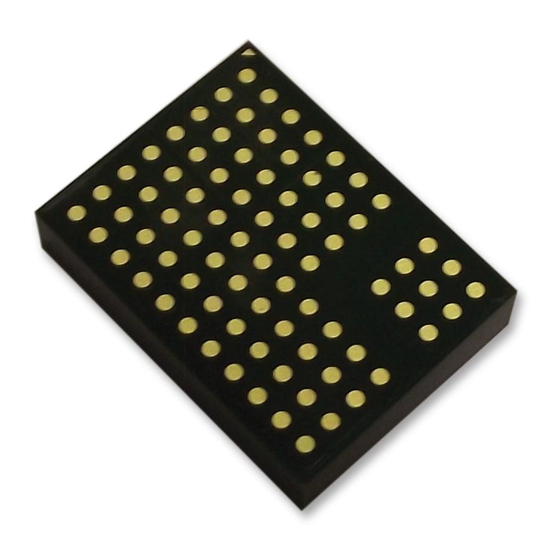
(11.25mm × 15mm × 2.82mm) LGA and (11.25mm
n
× 15mm × 3.42mm BGA Packages
APPLICATIONS
SuperCap Charging
n
General Purpose Industrial
n
Extreme Short-Circuit Protection or Accurate Output
n
Current Limit
µController-Based Battery Charging
n
High Power LED Drive
n
Multiple Input, Single Output Voltage Conversion
n
TYPICAL APPLICATION
V
IN
6V TO 36V
10µF
Typical Application
LTM8026
V
V
IN
OUT
510k
RUN
SS
V
REF
SYNC
CTL_I
COMP
CTL_T
RT
GND
ADJ
90.9k
9.09k
For more information
36V
, 5A CVCC Step-Down
IN
µModule Regulator
DESCRIPTION
The
LTM
8026
is a 36V
®
current (CVCC) step-down µModule
the package are the switching controller, power switches,
inductor and support components. Operating over an
input voltage range of 6V to 36V, the LTM8026 supports
an output voltage range of 1.2V to 24V. CVCC operation
allows the LTM8026 to accurately regulate its output
current up to 5A over the entire output range. The output
current can be set by a control voltage, a single resistor or
a thermistor. Only resistors to set the output voltage and
frequency and the bulk input and output filter capacitors
are needed to finish the design.
The LTM8026 is packaged in a thermally-enhanced,
compact (11.25mm × 15mm) overmolded land grid ar-
ray (LGA) and ball grid array (BGA) packages suitable for
automated assembly by standard surface mount equip-
ment. The LTM8026 is available in SnPb (BGA) or RoHS
compliant terminal finish.
L, LT, LTC, LTM, µModule, Linear Technology and the Linear logo are registered trademarks of
Analog Devices Inc. All other trademarks are the property of their respective owners. Protected
by U.S. Patents including 7199560, 7321203 and others pending.
3.0
V
OUT
2.5V
2.5
5A
+
2.0
100µF
330µF
1.5
1.0
0.5
8026 TA01a
www.linear.com/LTM8026
LTM8026
, 5A constant-voltage, constant-
IN
regulator. Included in
®
V
vs I
, 12V
OUT
OUT
IN
0
0
1
2
3
4
5
OUTPUT CURRENT (A)
6
8026 TA01b
8026fd
1
Advertisement
Table of Contents

Related Manuals for Analog Devices Linear Technology LTM8026


Summary of Contents for Analog Devices Linear Technology LTM8026
- Page 1 L, LT, LTC, LTM, µModule, Linear Technology and the Linear logo are registered trademarks of µController-Based Battery Charging Analog Devices Inc. All other trademarks are the property of their respective owners. Protected by U.S. Patents including 7199560, 7321203 and others pending.
-
Page 2: Absolute Maximum Ratings
LTM8026 ABSOLUTE MAXIMUM RATINGS (Note 1) ................40V Current Into RUN Pin ..........100µA ADJ, RT, COMP, CTL_I, CTL_T, V ......3V Internal Operating Temperature Range .. –40°C to 125°C ................25V Peak Solder Reflow Body Temperature ....245°C RUN, SYNC, SS ............6V Storage Temperature......–55°C to 125°C PIN CONFIGURATION http://www.linear.com/product/LTM8026#orderinfo TOP VIEW... -
Page 3: Electrical Characteristics
LTM8026 ELECTRICAL CHARACTERISTICS denotes the specifications which apply over the full internal operating temperature range, otherwise specifications are at T = 25°C. RUN = 3V, unless otherwise noted. (Note 3) PARAMETER CONDITIONS UNITS Minimum Input Voltage Output DC Voltage = 1A, R Open = 1A, R = 499Ω... -
Page 4: Typical Performance Characteristics
LTM8026 TYPICAL PERFORMANCE CHARACTERISTICS = 25°C, unless otherwise noted. Configured per Table 1, where applicable. 1.2V Efficiency 1.5V Efficiency 1.8V Efficiency vs Output Current vs Output Current vs Output Current OUTPUT CURRENT (A) OUTPUT CURRENT (A) OUTPUT CURRENT (A) 8026 G01 8026 G02 8026 G03 2.5V... - Page 5 LTM8026 TYPICAL PERFORMANCE CHARACTERISTICS = 25°C, unless otherwise noted. = 25°C, unless otherwise noted. Configured per Table 1, where applicable. Efficiency –3.3V Efficiency –5V Efficiency vs Output Current vs Output Current vs Output Current OUTPUT CURRENT (A) OUTPUT CURRENT (A) OUTPUT CURRENT (A) 8026 G10 8026 G11...
- Page 6 LTM8026 TYPICAL PERFORMANCE CHARACTERISTICS = 25°C, unless otherwise noted. Configured per Table 1, where applicable. Input Current vs Output Current Input Current vs Output Current Input Current vs Output Current 3.3V OUTPUT CURRENT (A) OUTPUT CURRENT (A) OUTPUT CURRENT (A) 8026 G19 8026 G20 8026 G21...
- Page 7 LTM8026 TYPICAL PERFORMANCE CHARACTERISTICS = 25°C, unless otherwise noted. Configured per Table 1, where applicable. Input Current vs Load Current Input Current vs Load Current Minimum Required Input Running –8V –12V Voltage vs Negative Output Voltage = 4A = 3A = 2A = 1A –5...
- Page 8 LTM8026 TYPICAL PERFORMANCE CHARACTERISTICS = 25°C, unless otherwise noted. Configured per Table 1, where applicable. Minimum Required Input Voltage Minimum Required Input Voltage Minimum Required Input Voltage vs Load 24V vs Load –3.3V vs Load –5V 28.0 TO START TO START RUN CONTROLLED RUN CONTROLLED TO RUN...
- Page 9 LTM8026 TYPICAL PERFORMANCE CHARACTERISTICS = 25°C, unless otherwise noted. Configured per Table 1, where applicable. Temperature Rise vs Load Current Temperature Rise vs Load Current Temperature Rise vs Load Current LOAD CURRENT (A) LOAD CURRENT (A) LOAD CURRENT (A) 8026 G47 8026 G46 8026 G48 Temperature Rise vs Load Current...
-
Page 10: Pin Functions
LTM8026 TYPICAL PERFORMANCE CHARACTERISTICS = 25°C, unless otherwise noted. Configured per Table 1, where applicable. CTL_I Voltage vs Load Current, CTL_T Voltage vs Load Current, CTL_T = 2V CTL_I = 2V LOAD CURRENT (A) LOAD CURRENT (A) 8026 G55 8026 G54 PIN FUNCTIONS CTL_I (Pin E8): The CTL_I pin reduces the maximum (Bank 1): Power Output Pins. -
Page 11: Block Diagram
LTM8026 PIN FUNCTIONS SS (Pin J8): The Soft-Start Pin. Place an external capacitor higher than the absolute maximum voltage of 6V through a to ground to limit the regulated current during start-up resistor, provided the pin current does not exceed 100µA. conditions. -
Page 12: Operation
LTM8026 OPERATION The LTM8026 is a standalone nonisolated step-down The RUN pin functions as a precision shutdown pin. When switching DC/DC power supply that can deliver up to 5A of the voltage at the RUN pin is lower than 1.55V, switch- output current. -
Page 13: Applications Information
LTM8026 APPLICATIONS INFORMATION For most applications, the design process is straight While these component combinations have been tested for forward, summarized as follows: proper operation, it is incumbent upon the user to verify proper operation over the intended system’s line, load and 1. - Page 14 LTM8026 APPLICATIONS INFORMATION graphs in the Typical Performance Characteristics section input voltage can ring to twice its nominal value, possi- for guidance. bly exceeding the device’s rating. This situation is easily avoided; see the Hot Plugging Safely section. The maximum frequency (and attendant R value) at which the LTM8026 should be allowed to switch is given Programming Switching Frequency...
- Page 15 LTM8026 APPLICATIONS INFORMATION may be set from 100kHz to 1MHz. The internal oscillator Load Current Derating Using the CTL_T Pin may also be synchronized to an external clock through In high current applications, derating the maximum current the SYNC pin. The external clock applied to the SYNC pin based on operating temperature may prevent damage must have a logic low below 0.6V and a logic high greater to the load.
- Page 16 LTM8026 APPLICATIONS INFORMATION down switching for 13µs. The regulated output voltage divider resistors for programming the falling UVLO voltage must be greater than 1.21V and is set by the equation: and rising enable voltage (V ) as configured in Figure 4. 11.9 1.55 •...
- Page 17 LTM8026 APPLICATIONS INFORMATION LTM8026s equally sharing output current is shown in the Typical Applications section. The modulation of the CTL_I inputs is performed at a high bandwidth, so use an op amp with a gain bandwidth product greater than 1MHz. The example circuit in the Typical Applications section •...
- Page 18 LTM8026 APPLICATIONS INFORMATION 3. Place the C capacitor as close as possible to the damps the circuit and eliminates the voltage overshoot. and GND connection of the LTM8026. The extra capacitor improves low frequency ripple filter- ing and can slightly improve the efficiency of the circuit, 4.
- Page 19 LTM8026 APPLICATIONS INFORMATION θ is the junction-to-board thermal resistance with Given these definitions, it should now be apparent that none JCbottom all of the component power dissipation flowing through the of these thermal coefficients reflects an actual physical bottom of the package. In the typical µModule regulator, operating condition of a µModule regulator.
-
Page 20: Typical Applications
LTM8026 TYPICAL APPLICATIONS , 3.3V Step-Down CVCC Converter LTM8026 3.3V 6V TO 36V 510k 10µF 330µF SYNC CTL_I 100µF COMP CTL_T 75.0k 5.62k 8026 TA02 , 5.6A Two 2.5V Series Supercapacitor Charger LTM8026 7V TO 36V 510k 10µF 2.5V 2.2F 47µF SYNC CTL_I... - Page 21 LTM8026 TYPICAL APPLICATIONS , –5V Negative CVCC Converter LTM8026 7V TO 31V 10µF 120µF 2N3906 SYNC CTL_I 100µF OPTIONAL COMP CTL_T 68.1k 3.09k –5V 8026 TA05 OPTIONAL: SEE DESIGN NOTE 1021 Two LTM8026s Operating in Parallel to Produce 2.5V at 10A LTM8026 2.5V 6V TO 36V...
- Page 22 LTM8026 TYPICAL APPLICATIONS Two LTM8026s Operating in Parallel to Produce 2.5V at 10A, Equally Sharing Current LTM8026 2.5V 6V TO 36V 324k 10µF SYNC CTL_T 100µF COMP CTL_I 4.02k 470pF 680k LTM8026 0.47µF 100µF 150k 100k 330µF SYNC CTL_T LTC6255 COMP CTL_I 0.1µF...
- Page 23 LTM8026 TYPICAL APPLICATIONS Two LTM8026s Running from 12V and 24V. At Max Load, Each LTM8026 Draws Less Than 750mA from Their Respective Input Sources LTM8026 <750mA REGULATED 2.5V 324k 10µF SYNC CTL_I 100µF COMP CTL_T 66.5k 90.9k 4.53k 140k LTM8026 <750mA REGULATED 10µF...
-
Page 24: Package Description
LTM8026 PACKAGE DESCRIPTION Table 3. Pin Assignment Table (Arranged by Pin Number) NAME NAME NAME NAME NAME NAME CTL_T CTL_I NAME NAME NAME NAME NAME SYNC COMP PACKAGE PHOTO 2.82mm 3.42mm 15mm 15mm 11.25mm 11.25mm 8026fd For more information www.linear.com/LTM8026... - Page 25 LTM8026 PACKAGE DESCRIPTION Please refer to http://www.linear.com/product/LTM8026#packaging for the most recent package drawings. 8026fd For more information www.linear.com/LTM8026...
- Page 26 LTM8026 PACKAGE DESCRIPTION Please refer to http://www.linear.com/product/LTM8026#packaging for the most recent package drawings. 8026fd For more information www.linear.com/LTM8026...
-
Page 27: Revision History
LTM8026 REVISION HISTORY DATE DESCRIPTION PAGE NUMBER 8/12 Added MP-Grade 5/13 Update maximum solder temperature Update Package Description drawing 07/15 Added BGA Package 1, 2, 26 06/17 Corrected Device Part Marking of LTM8026MPV#PBF 8026fd Information furnished by Linear Technology Corporation is believed to be accurate and reliable. However, no responsibility is assumed for its use. -
Page 28: Typical Application
LTM8026 TYPICAL APPLICATION , 3.3V Step-Down Converter with 4.75A Accurate Current Limit LTM8026 3.3V 6V TO 36V 510k 4.75A 10µF SYNC CTL_I 100µF 330µF COMP CTL_T 71.5k 5.62k 127k 8026 TA08 DESIGN RESOURCES SUBJECT DESCRIPTION µModule Design and Manufacturing Resources Design: Manufacturing: •...
Need help?
Do you have a question about the Linear Technology LTM8026 and is the answer not in the manual?
Questions and answers