Advertisement
DESCRIPTION
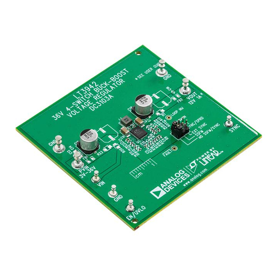
Demonstration circuit DC3103A is a monolithic 4-Switch
buck-boost voltage regulator featuring the
has been designed with an output voltage set to 12V with
capability of delivering up to 1A when the input voltage is
between 7V and 36V. The demonstration circuit continues
operating with an input voltage as low as 3V with reduced
output power capability. DC3103A is configured for 2MHz
switching frequency with spread spectrum frequency
modulation (SSFM) disabled. When enabled, SSFM
adjusts the switching frequency of the LT3942 between
2MHz and 2.5MHz for improved EMI performance.
The LT3942 has an operating input voltage range of 3V
to 36V. It has internal, synchronous 40V switches for
high efficiency and small size. It has an adjustable switch-
ing frequency between 300kHz and 2MHz. The LT3942
can by synchronized to an external oscillator source,
programmed with SSFM enabled for low EMI, or set to
normal operation.
The board is designed with ceramic capacitors placed
near the PVIN and PVOUT pins to form a compact high
frequency hotloop. SMD pads are available to install an
optional ferrite bead EMI filter on both the input and
output of DC3103A. Small cuts on the top layer copper
between the SMD pads of both ferrite bead components
are necessary to install the EMI filter correctly. These
DEMO MANUAL DC3103A
36V 4-Switch Buck-Boost
filters, combined with proper board layout and SSFM,
LT
3942. It
are effective in reducing both radiated and conducted EMI.
®
Please follow the recommended layout and four-layer PCB
thickness of DC3103A for low EMI applications.
DC3103A uses the LT3942's voltage regulation loop to
program a constant-voltage output of 12V. The LT3942
can operate as a constant voltage regulator as well as
a constant current regulator. For LED driver designs,
please refer to demonstration circuit DC2404A. DC2404A
includes a high-side PMOS disconnect switch to assist
with PWM dimming, as well as several other optimizations
for LED driver applications.
The LT3942 datasheet gives a complete description of the
part, operation, and applications information. The data-
sheet must be read in conjunction with this User Guide
for DC3103A. The LT3942EUFD is assembled in a 28-lead
plastic QFN (UFD) package with a thermally-enhanced
exposed ground pad. Proper board layout is essential for
maximum thermal and low-noise performance. Refer to
DC3103A's design files files for recommended layout and
routing of the LT3942 for voltage regulator applications.
Design files for this circuit board are
All registered trademarks and trademarks are the property of their respective owners.
Voltage Regulator
available.
LT3942
Rev. 0
1
Advertisement
Table of Contents

Related Manuals for Analog Devices DC3103A


Summary of Contents for Analog Devices DC3103A
- Page 1 EMI filter on both the input and Design files for this circuit board are available. output of DC3103A. Small cuts on the top layer copper All registered trademarks and trademarks are the property of their respective owners. between the SMD pads of both ferrite bead components are necessary to install the EMI filter correctly.
-
Page 2: Performance Summary
= 12V, Not Switching EN/UVLO QUICK START PROCEDURE Demonstration circuit DC3103A is easy to set up to evaluate 5. Turn the input power supply on and adjust the voltage the performance of the LT3942. Follow the procedure below. between 7V and 36V for full output power capability and accurate 12V output regulation. - Page 3 = 12V = 12V 12PV = 1A 24PV = 0.5A 36PV 0.01 Figure 2. DC3103A Efficiency vs Input Voltage, SSFM OFF Figure 3. DC3103A Efficiency vs Load Current, SSFM OFF DC3103A DC3103A Output Transient Response Output Ripple (V = 12V I =1A)
-
Page 4: Parts List
DEMO MANUAL DC3103A PARTS LIST ITEM REFERENCE PART DESCRIPTION MANUFACTURER/PART NUMBER Required Circuit Components CAP ., 10uF , X5R, 50V, 10%, 1206 TAIYO YUDEN, UMK316BBJ106KL-T CAP ., 0.47uF , X5R, 50V, 10%, 0402 MURATA, GRM155R61H474KE11D CAP ., 2.2uF , X5R, 6.3V, 10%, 0402... -
Page 5: Schematic Diagram
Devices for its use, nor for any infringements of patents or other rights of third parties that may result from its use. Specifications subject to change without notice. No license is granted by implication or otherwise under any patent or patent rights of Analog Devices. - Page 6 Board until you have read and agreed to the Agreement. Your use of the Evaluation Board shall signify your acceptance of the Agreement. This Agreement is made by and between you (“Customer”) and Analog Devices, Inc. (“ADI”), with its principal place of business at One Technology Way, Norwood, MA 02062, USA. Subject to the terms and conditions of the Agreement, ADI hereby grants to Customer a free, limited, personal, temporary, non-exclusive, non-sublicensable, non-transferable license to use the Evaluation Board FOR EVALUATION PURPOSES ONLY.
Need help?
Do you have a question about the DC3103A and is the answer not in the manual?
Questions and answers