Table of Contents
Advertisement
Quick Links
One Technology Way • P.O. Box 9106 • Norwood, MA 02062-9106, U.S.A. • Tel: 781.329.4700 • Fax: 781.461.3113 • www.analog.com
INTRODUCTION
This user guide describes the
demonstration platform—Blackfin® (SDP-B) controller board
from Analog Devices, Inc. The SDP-B controller board is part
of the Analog Devices system demonstration platform (SDP).
The SDP consists of a series of controller boards, interposer
boards, and daughter boards.
SDP controller boards provide a means of communicating with
the PC from the system under evaluation. Interposer boards
route signals between two connectors. Daughter boards are a
collection of product evaluation boards and Circuits from the
Lab™ reference circuit boards. The SDP-B is used as part of the
evaluation system for many Analog Devices components and
reference circuits. The primary audience for this user guide is a
system engineer who seeks to understand how to set up the
SDP-B board and begin USB communications to the PC.
PLEASE SEE THE LAST PAGE FOR AN IMPORTANT
WARNING AND LEGAL TERMS AND CONDITIONS.
SDP-B Controller Board
EVAL-SDP-CB1Z
system
The SDP-B board is designed to be used in conjunction with
various Analog Devices component evaluation boards and
Circuits from the Lab reference circuits as part of a customer
evaluation environment. The SDP-B provides USB connectivity
through a USB 2.0 high speed connection to the computer
allowing users to evaluate components on this platform from a
PC application. The SDP-B is based on
processor, with the Blackfin processor peripheral communi-
cation lines available to the component daughter board through
two identical 120-pin small footprint connectors.
The SDP-B user guide provides instructions for installing the
SDP-B hardware (EVAL-SDP-CB1Z board) and software onto
your computer. The necessary installation files are provided
with the evaluation daughter board package. The Getting
Started section provides software and hardware installation
procedures, PC system requirements, and basic board informa-
tion. The Hardware Description section provides information
on the EVAL-SDP-CB1Z components. The EVAL-SDP-CB1Z
schematics are provided in the Schematics section.
Rev. B | Page 1 of 24
SDP User Guide
UG-277
ADSP-BF527
Blackfin
Advertisement
Table of Contents

Related Manuals for Analog Devices SDP-B


Summary of Contents for Analog Devices SDP-B
-
Page 1: Introduction
120-pin small footprint connectors. collection of product evaluation boards and Circuits from the Lab™ reference circuit boards. The SDP-B is used as part of the The SDP-B user guide provides instructions for installing the SDP-B hardware (EVAL-SDP-CB1Z board) and software onto evaluation system for many Analog Devices components and reference circuits. -
Page 2: Table Of Contents
UG-277 SDP User Guide TABLE OF CONTENTS Introduction ..................1 USB Installation ................4 Revision History ................2 Powering Up/Powering Down the SDP ........4 Product Overview ................3 Hardware Description...............5 Technical or Customer Support..........3 LEDs ....................5 Product Information ..............3 Connector Details .................5 Regulatory Compliance ............... -
Page 3: Product Overview
SDP User Guide UG-277 PRODUCT OVERVIEW The SDP-B board features PRODUCT INFORMATION • Product information can be obtained from the Analog Devices Analog Devices ADSP-BF527 Blackfin processor • website. Core performance up to 600 MHz • 208-ball CSP-BGA package Analog Devices Web Site •... -
Page 4: Getting Started
Connecting the SDP-B Board to the PC Disconnect the SDP-B board from the daughter evaluation Attach the SDP-B board to a USB 2.0 port on the computer via board. the Standard-A to Mini-B cable provided. Rev. B | Page 4 of 24... -
Page 5: Hardware Description
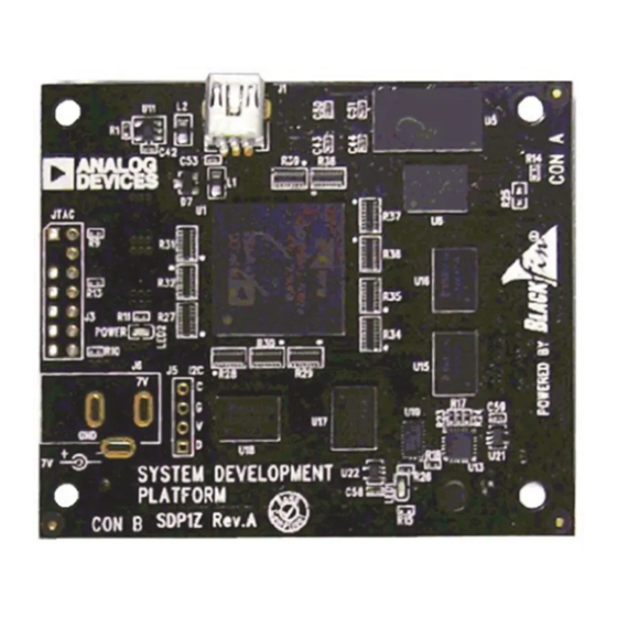
Mechanical specifications—This section provides dimensional information. exposed. The exposed peripherals are • LEDS • SPORT There are two LEDs located on the SDP-B board (see Figure 2). • C/TWI POWER LED • GPIO The green power LED indicates that the SDP-B board is •... - Page 6 UG-277 SDP User Guide Table 1. 120-Pin Connector Pin Assignments Pin No. Pin Name Description Power to SDP Board. Requires 200 mA at 5 V. No Connect. Leave this pin unconnected. Do not ground. Connect to ground plane of board. Connect to ground plane of board.
- Page 7 SDP User Guide UG-277 Pin No. Pin Name Description No Connect. Leave this pin unconnected. Do not ground. Connect to ground plane of board. No Connect. Leave this pin unconnected. Do not ground. No Connect. Leave this pin unconnected. Do not ground. No Connect.
- Page 8 Functionality not implemented on the SDP board. Shared across both connectors. Each interface provided by the SDP-B is available on unique pins of the SDP-B 120-pin connector. The connector pin numbering scheme is outlined in Figure 3. Rev. B | Page 8 of 24...
- Page 9 SDP User Guide UG-277 RESET_IN BMODE1 UART_RX UART_TX RESET_OUT SLEEP EEPROM_A0 WAKE STANDARD CONNECTOR TMR_C TMR_D TIMERS TMR_A TMR_B GPIO6 GPIO7 GENERAL GPIO4 GPIO5 INPUT/OUTPUT GPIO2 GPIO3 GPIO0 GPIO1 SCL_1 SCL_0 SDA_1 SDA_0 SPI_CLK SPI_SEL1/SPI_SS SPI_SEL_C SPI_MISO SPI_SEL_B SPI_MOSI SPI_SEL_A SERIAL_INT SPI_D3 SPORT_TSCLK...
-
Page 10: Power
The SDP-B board requires that any daughter board connected Two types of pin sharing occur on the SDP-B board and must to the SDP-B board provides the SDP-B board with 5 V at 200 be considered when using two or more of the connector’s mA. - Page 11 SDP User Guide UG-277 5.9mm 3.3mm DAUGHTERBOARD A DAUGHTERBOARD B 3.3mm 5.9mm Figure 4. Maximum Board Dimensions for Connector Placement The full specification drawing for the connector location on the daughter board can be seen in Figure 5. 1.75mm 5.90mm NO RIGHT-ANGLED CONNECTORS ALLOWED ALONG THIS EDGE ORIGIN (0,0) 3.30mm...
-
Page 12: Mechanical Specifications
MECHANICAL SPECIFICATIONS Keep Out Area The mechanical specifications of the SDP-B board are 2.75" × In order to allow the greatest flexibility for future controller 2.25" (69.85 mm × 27.15 mm). The height of the 120-pin con- boards, a keep out area is established for components higher nectors from the bottom of the board is approximately 0.152"... -
Page 13: Replaced Schematics Section
UG-277 SCHEMATICS This section provides the schematic drawings for the EVAL-SDP-CB1Z board. The schematic pages include • SDP-B—Power • SDP-B—Memory • SDP-B—Clocks_USB • SDP-B—Blackfin_I/O • SDP-B—Connector A • SDP-B—Connector B • SDP-B—Connector C Rev. B | Page 13 of 24... -
Page 14: Revision History 12/11-Rev. A To Rev. B Changes To Figure 7
UG-277 SDP User Guide Figure 7. SDP-B —Power Rev. B | Page 14 of 24... -
Page 15: Changes To Figure 8
SDP User Guide UG-277 Figure 8. SDP-B —Memory Rev. B | Page 15 of 24... -
Page 16: Changes To Figure 9
UG-277 SDP User Guide Figure 9. SDP-B —Clocks_USB Rev. B | Page 16 of 24... -
Page 17: Changes To Figure 10
SDP User Guide UG-277 Figure 10. SDP-B —Blackfin_I/O Rev. B | Page 17 of 24... -
Page 18: Changes To Figure 11
UG-277 SDP User Guide Figure 11. SDP-B —Connector A Rev. B | Page 18 of 24... -
Page 19: Changes To Figure 12
SDP User Guide UG-277 Figure 12. SDP-B —Connector B Rev. B | Page 19 of 24... -
Page 20: Changes To Figure 13
UG-277 SDP User Guide Figure 13. SDP-B —Connector C Rev. B | Page 20 of 24... - Page 21 SDP User Guide UG-277 NOTES Rev. B | Page 21 of 24...
- Page 22 UG-277 SDP User Guide NOTES Rev. B | Page 22 of 24...
- Page 23 SDP User Guide UG-277 NOTES Rev. B | Page 23 of 24...
- Page 24 By using the evaluation board discussed herein (together with any tools, components documentation or support materials, the “Evaluation Board”), you are agreeing to be bound by the terms and conditions set forth below (“Agreement”) unless you have purchased the Evaluation Board, in which case the Analog Devices Standard Terms and Conditions of Sale shall govern. Do not use the Evaluation Board until you have read and agreed to the Agreement.
Need help?
Do you have a question about the SDP-B and is the answer not in the manual?
Questions and answers