Table of Contents
Advertisement
Please file and use this manual together with Wireless LAN Module Setup Instructions Order No. ACXF55-33580
This service information is designed for experienced repair technicians only and is not designed for use by the general public.
It does not contain warnings or cautions to advise non-technical individuals of potential dangers in attempting to service a product.
Products powered by electricity should be serviced or repaired only by experienced professional technicians. Any attempt to service
or repair the products dealt with in this service information by anyone else could result in serious injury or death.
There are special components used in this equipment which are important for safety. These parts are marked by
Diagrams, Circuit Board Diagrams, Exploded Views and Replacement Parts List. It is essential that these critical parts should be replaced
with manufacturer's specified parts to prevent shock, fire or other hazards. Do not modify the original design without permission of
manufacturer.
In order to avoid frostbite, be assured of no refrigerant leakage during the installation or repairing of refrigerant circuit.
R32 REFRIGERANT
– This Air Conditioner contains and operates with refrigerant R32.
THIS PRODUCT MUST ONLY BE INSTALLED OR SERVICED BY QUALIFIED PERSONNEL.
Refer to National, State, Territory and local legislation, regulations, codes, installation & operation manuals, before the installation,
maintenance and/or service of this product.
12:00,Mon
SET TEMP. FAN SPEED
MODE
AUTO
25
AUTO
.0
FLAP
AUTO
WARNING
IMPORTANT SAFETY NOTICE
PRECAUTION OF LOW TEMPERATURE
CAUTION
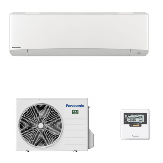
Indoor Unit
CS-Z25YKEA
CS-Z35YKEA
CS-Z42YKEA
CS-Z50YKEA
CS-Z71YKEA
Order No: PAPAMY2202080CE
Outdoor Unit
CU-Z25YKEA
CU-Z35YKEA
CU-Z42YKEA
CU-Z50YKEA
CU-Z71YKEA
Destination
Europe
Turkey
in the Schematic
© Panasonic Corporation 2022.
Advertisement
Table of Contents

Related Manuals for Panasonic CS-Z25YKEA


Summary of Contents for Panasonic CS-Z25YKEA
- Page 1 – This Air Conditioner contains and operates with refrigerant R32. THIS PRODUCT MUST ONLY BE INSTALLED OR SERVICED BY QUALIFIED PERSONNEL. Refer to National, State, Territory and local legislation, regulations, codes, installation & operation manuals, before the installation, maintenance and/or service of this product. © Panasonic Corporation 2022.
-
Page 2: Table Of Contents
Self-diagnosis Method ......125 9. Wiring Connection Diagram ......44 18. Disassembly and Assembly Instructions ... 155 Indoor Unit ..........44 Outdoor Unit ..........45 18.1 CS-Z25YKEA CS-Z35YKEA CS-Z42YKEA ........... 155 10. Electronic Circuit Diagram ......47 18.2 CS-Z50YKEA CS-Z71YKEA ....162 10.1... -
Page 3: Safety Precautions
1. Safety Precautions Read the following “SAFETY PRECAUTIONS” carefully before installation. Electrical work must be installed by a licensed electrician. Be sure to use the correct rating of the power plug and main circuit for the model to be installed. ... - Page 4 WARNING Do not use joint cable for indoor / outdoor connection cable. Use the specified indoor/outdoor connection cable, refer to instruction CONNECT THE CABLE TO THE INDOOR UNIT and connect tightly for indoor/outdoor connection. Clamp the cable so that no external force will have impact on the terminal.
-
Page 5: Precaution For Using R32 Refrigerant
2. Precaution for Using R32 Refrigerant Pay careful attention to the following precaution points and the installation work procedures. WARNING When connecting flare at indoor side, make sure that the flare connection is used only once, if torqued up and released, the flare must be remade. - Page 6 CAUTION General Must ensure the installation of pipe-work shall be kept to a minimum. Avoid use dented pipe and do not allow acute bending. Must ensure that pipe-work shall be protected from physical damage. Must comply with national gas regulations, state municipal rules and legislation. Notify relevant authorities in accordance with all applicable regulations.
- Page 7 CAUTION 2-10. Checks to electrical devices Repair and maintenance to electrical components shall include initial safety checks and component inspection procedures. Initial safety checks shall include but not limit to:- That capacitors are discharged: this shall be done in a safe manner to avoid possibility of sparking. That there is no live electrical components and wiring are exposed while charging, recovering or purging the system.
- Page 8 CAUTION Removal and evacuation When breaking into the refrigerant circuit to make repairs – or for any other purpose – conventional procedures shall be used. However, it is important that best practice is followed since flammability is a consideration. The following procedure shall be adhered to: •...
- Page 9 CAUTION Recovery When removing refrigerant from a system, either for servicing or decommissioning, it is recommended good practice that all refrigerants are removed safely. When transferring refrigerant into cylinders, ensure that only appropriate refrigerant recovery cylinders are employed. ...
-
Page 10: Specifications
3. Specifications Indoor CS-Z25YKEA Model Outdoor CU-Z25YKEA Performance Test Condition EUROVENT Phase, Hz Single, 50 Power Supply Min. Mid. Max. 0.85 2.50 3.50 Capacity BTU/h 2900 8530 11900 kcal/h 2150 3010 Running Current 2.35 Input Power Annual Consumption EER Class 4.72... - Page 11 Indoor CS-Z25YKEA Model Outdoor CU-Z25YKEA Type Hermetic Motor / Rotary Compressor Motor Type Brushless (6-poles) Output Power Type Cross-flow fan Material ASG30 Motor Type DC (8-pole) Input Power 47.1 Output Power Cool Heat Cool Heat Cool Speed Heat Cool Heat...
- Page 12 Indoor CS-Z25YKEA Model Outdoor CU-Z25YKEA Height (ID / OD) mm (inch) 295 (11-5/8) / 542 (21-11/32) Dimension Unit Width (ID / OD) mm (inch) 870 (34-9/32) / 780 (30-23/32) Depth (ID / OD) mm (inch) 229 (9-1/32) / 289 (11-13/32)
- Page 13 Indoor CS-Z35YKEA Model Outdoor CU-Z35YKEA Performance Test Condition EUROVENT Phase, Hz Single, 50 Power Supply Min. Mid. Max. 0.85 3.50 4.20 Capacity BTU/h 2900 11900 14300 kcal/h 3010 3610 Running Current 3.80 Input Power 1.14k Annual Consumption EER CLASS 4.72 4.12 3.68 BTU/hW...
- Page 14 Indoor CS-Z35YKEA Model Outdoor CU-Z35YKEA Type Hermetic Motor / Rotary Compressor Motor Type Brushless (6-poles) Output Power Type Cross-flow fan Material ASG30 Motor Type DC (8-pole) Input Power 47.1 Output Power Cool Heat Cool Heat Cool Speed Heat Cool 1000 Heat 1130 Cool...
- Page 15 Indoor CS-Z35YKEA Model Outdoor CU-Z35YKEA Height (ID / OD) mm (inch) 295 (11-5/8) / 542 (21-11/32) Dimension Unit Width (ID / OD) mm (inch) 870 (34-9/32) / 780 (30-23/32) Depth (ID / OD) mm (inch) 229 (9-1/32) / 289 (11-13/32) Weight Net (I/D / O/D) kg (lb)
- Page 16 Indoor CS-Z42YKEA Model Outdoor CU-Z42YKEA Performance Test Condition EUROVENT Phase, Hz Single, 50 Power Supply Min. Mid. Max. 0.85 4.20 5.00 Capacity BTU/h 2900 14300 17100 kcal/h 3610 4300 Running Current 4.90 Input Power 1.10k 1.54k Annual Consumption EER CLASS 4.72 3.82 3.25...
- Page 17 Indoor CS-Z42YKEA Model Outdoor CU-Z42YKEA Type Hermetic Motor / Rotary Compressor Motor Type Brushless (6-poles) Output Power Type Cross-flow fan Material ASG30 Motor Type DC (8-pole) Input Power 47.1 Output Power Cool Heat Cool Heat Cool Speed Heat 1010 Cool 1030 Heat 1160...
- Page 18 Indoor CS-Z42YKEA Model Outdoor CU-Z42YKEA Height (ID / OD) mm (inch) 295 (11-5/8) / 542 (21-11/32) Dimension Unit Width (ID / OD) mm (inch) 870 (34-9/32) / 780 (30-23/32) Depth (ID / OD) mm (inch) 229 (9-1/32) / 289 (11-13/32) Weight Net (I/D / O/D) kg (lb)
- Page 19 Indoor CS-Z50YKEA Model Outdoor CU-Z50YKEA Performance Test Condition EUROVENT Phase, Hz Single, 50 Power Supply Min. Mid. Max. 0.98 5.00 6.00 Capacity BTU/h 3340 17100 20500 kcal/h 4300 5160 Running Current 6.00 Input Power 1.36k 1.90k Annual Consumption EER CLASS 3.92 3.68 3.16...
- Page 20 Indoor CS-Z50YKEA Model Outdoor CU-Z50YKEA Type Hermetic Motor / Rotary Compressor Motor Type Brushless (6-pole) Output Power Type Cross-flow fan Material ASG30 Motor Type DC (8-pole) Input Power 74.0 Output Power Cool Heat Cool Heat Cool Speed Heat 1010 Cool 1050 Heat 1140...
- Page 21 Indoor CS-Z50YKEA Model Outdoor CU-Z50YKEA Height (ID / OD) mm (inch) 295 (11-5/8) / 695 (27-3/8) Dimension Unit Width (ID / OD) mm (inch) 1040 (40-31/32) / 875 (34-15/32) Depth (ID / OD) mm (inch) 244 (9-5/8) / 320 (12-5/8) Weight Net (I/D / O/D) kg (lb)
- Page 22 Indoor CS-Z71YKEA Model Outdoor CU-Z71YKEA Performance Test Condition EUROVENT Phase, Hz Single, 50 Power Supply Min. Mid. Max. 0.98 7.10 8.50 Capacity BTU/h 3340 24200 29000 kcal/h 6110 7310 Running Current 9.80 Input Power 2.20k 3.00k Annual Consumption 1100 EER CLASS 2.33 3.23 2.83...
- Page 23 Indoor CS-Z71YKEA Model Outdoor CU-Z71YKEA Type Hermetic Motor / Rotary Compressor Motor Type Brushless (6-pole) Output Power 1.50k Type Cross-flow fan Material ASG30 Motor Type DC (8-pole) Input Power 80.2 Output Power Cool Heat Cool Heat Cool 1070 Speed Heat 1080 Cool 1200...
- Page 24 Indoor CS-Z71YKEA Model Outdoor CU-Z71YKEA Height (ID / OD) mm (inch) 295 (11-5/8) / 695 (27-3/8) Dimension Unit Width (ID / OD) mm (inch) 1040 (40-31/32) / 875 (34-15/32) Depth (ID / OD) mm (inch) 244 (9-5/8) / 320 (12-5/8) Weight Net (I/D / O/D) kg (lb)
-
Page 25: Features
4. Features Inverter Technology Wider output power range Energy saving Quick Cooling Quick Heating More precise temperature control Environment Protection Non-ozone depletion substances refrigerant (R32) Long Installation Piping Long piping up to 20 meter (Z25/35/42YKEA), 30 meters (Z50/70YKEA) meters during single split connection only ... -
Page 26: Location Of Controls And Components
5. Location of Controls and Components Indoor Unit Aluminium fin Front panel Auto OFF/ON button Use when remote control is misplaced or a malfunction occurs. Indicator Air Filters Horizontal airflow direction louver Do not adjust by hand. Vertical airflow direction louver Do not adjust by hand. -
Page 27: Remote Control
Remote Control 5.3.1 Remote Controller Buttons and Display Buttons / Indicator Quick Menu button Back button Returns to the previous screen 12:00,Mon SET TEMP. FAN SPEED LCD Display MODE AUTO Main Menu button AUTO For function setup FLAP ON/OFF button AUTO Starts/Stops operation Operation indicator... - Page 28 5.3.2 Initialization Please initiate the Remote Control by selecting the language of operation and set the date and time accordingly before setting up the operation menu preferences. During first power ON, Remote Controller will automatically prompt setting screen as default. It can also be access from Personal Setup in the Main Menu.
- Page 29 5.3.3 Quick Guide 5.3.3.1 Basic Operation 12:00,Mon SET TEMP. FAN SPEED MODE AUTO AUTO FLAP AUTO Fan speed section 1 Press to start/stop the • When FAN AUTO is selected, the fan operation. speed is adjusted automatically according to the operation mode. •...
- Page 30 5.3.4 Quick Menu Press to select quick menu. Press to turn on/off the select mode. Select To return to the Main Screen, Press Quick Menu Powerful Quiet Weekly timer LED intensity dim R/C Lock AC Reset RC Reset Select each setting and confi rm the setting according to the instructions displayed at the bottom of the screen.
- Page 31 Quiet Select this icon to enjoy quiet operation. Quiet mode reduces airfl ow noise. Press to confi rm your selection. When Quiet mode is selected, an icon will appear on top left of Main Screen. * Refer to "Remote Controller buttons and display" •...
- Page 32 LED intensity dim Select this icon to dim or restore the indicators’ brightness on the unit. R/C Lock Select this icon to lock the Remote Controller. Press to confi rm your selection. (When the mode has been accepted, below screen will be displayed.) Select “Yes”.
- Page 33 5.3.5 Main Menu Select menus and determine settings according to the system available in the household. • After initial installation, you may manually adjust Main menu 12:00,Mon the settings. Function setup • The initial setting remains active until the user System check changes it.
- Page 34 Disable in Quick Menu. Disable WLAN WLAN 12:00,Mon To apply the WLAN WLAN ON/OFF settings in Panasonic WLAN ON/OFF Easy setting (WPS) Comfort Cloud phone Easy Setting (WPS) Advance setting (AP) app. Advance setting (AP) Device registration...
- Page 35 t l u i t t i t t o i t System check To perform failure diagnosis. 12:00,Mon System check If the Error code matches with the error encountered, you will Select and retrieve No memory of failure hear a beeping sound. * Please refer to "Troubleshooting"...
- Page 36 t l u i t t i t t o i t Set temp. unit 12:00,Mon To set the temperature Set temp. unit unit. ˚C °C ˚F Select Confirm Set temp. decimal To set the temperature Enable decimal unit. Enable Disable Language Sets the display...
-
Page 37: Dimensions
6. Dimensions Indoor Unit 6.1.1 CS-Z25YKEA CS-Z35YKEA CS-Z42YKEA <Top View> <Side View> <Front View> <Side View> Air intake direction Air outlet Left piping Right piping direction hole hole <Bottom View> <Remote Control> 12:00,Mon SET TEMP. FAN SPEED MODE AUTO AUTO... - Page 38 6.1.2 CS-Z50YKEA CS-Z71YKEA <Top View> <Side View> <Front View> <Side View> Air intake 1040 direction Air outlet Left piping Right piping direction hole hole <Bottom View> <Remote Control> 12:00,Mon SET TEMP. FAN SPEED MODE AUTO AUTO FLAP AUTO <Rear View> <Remote Control Holder>...
-
Page 39: Outdoor Unit
Outdoor Unit 6.2.1 CU-Z25YKEA CU-Z35YKEA CU-Z42YKEA <Top View> Space necessary for installation 67.6 (104.7) 104.9 60.5 100 mm 100 mm 1000 mm 2-way valve at Liquid side Anchor Bolt Pitch (High Pressure) × 3-way valve at Gas side (Low Pressure) <Side View>... -
Page 40: Refrigeration Cycle Diagram
7. Refrigeration Cycle Diagram CS-Z25YKEA CU-Z25YKEA CS-Z35YKEA CU-Z35YKEA CS-Z42YKEA CU-Z42YKEA INDOOR OUTDOOR LIQUID DISCHARGE EXPANSION TEMP. SIDE MUFFLER VALVE STRAINER SENSOR 2-WAY VALVE PIPE TEMP. INTAKE SENSOR 2 TEMP. SENSOR CONDENSER PIPE TEMP. PIPE SENSOR 1 TEMP. SENSOR HEAT EXCHANGER... -
Page 41: Cs-Z50Ykea Cu-Z50Ykea
CS-Z50YKEA CU-Z50YKEA INDOOR OUTDOOR LIQUID EXPANSION TEMP. SIDE VALVE STRAINER STRAINER SENSOR 2-WAY VALVE PIPE TEMP. INTAKE SENSOR 2 TEMP. SENSOR CONDENSER PIPE TEMP. PIPE SENSOR 1 TEMP. SENSOR HEAT EXCHANGER (EVAPORATOR) SIDE 4-WAYS VALVE 3-WAY VALVE MUFFLER TANK SENSOR COMPRESSOR COOLING HEATING... -
Page 42: Cs-Z71Ykea Cu-Z71Ykea
CS-Z71YKEA CU-Z71YKEA INDOOR OUTDOOR LIQUID EXPANSION TEMP. SIDE RECEIVER VALVE STRAINER SENSOR 2-WAY VALVE PIPE TEMP. INTAKE SENSOR 2 TEMP. SENSOR CONDENSER PIPE TEMP. PIPE SENSOR 1 TEMP. SENSOR HEAT EXCHANGER (EVAPORATOR) SIDE 4-WAYS VALVE 3-WAY VALVE MUFFLER TANK SENSOR COMPRESSOR COOLING HEATING... -
Page 43: Block Diagram
8. Block Diagram... -
Page 44: Wiring Connection Diagram
9. Wiring Connection Diagram Indoor Unit... -
Page 45: Outdoor Unit
Outdoor Unit 9.2.1 CU-Z25YKEA CU-Z35YKEA CU-Z42YKEA (BLK) FUSE 4 FUSE 5 FUSE 1 AC-BRW (BRW) AC-BLU (BLU) FUSE 3 CN-STM1 (WHT) SOUND PROOF BOARD FUSE 2 IC19 Resistance of Compressor Windings CU-Z25YKEA / CU-Z35YKEA / MODEL CU-Z42YKEA CONNECTION 9RS102XRA21 (Ω) 2.389 2.389 2.389... - Page 46 9.2.2 CU-Z50YKEA CU-Z71YKEA (BLK) FUSE 4 FUSE 5 FUSE 1 AC-BRW (BRW) AC-BLU (BLU) FUSE 3 CN-STM1 (WHT) SOUND PROOF BOARD FUSE 2 IC19 Resistance of Compressor Windings MODEL CU-Z50YKEA MODEL CU-Z71YKEA CONNECTION 9RD132XGA21 (Ω) CONNECTION 9RD220XBA21 (Ω) 1.708 0.998 1.708 0.998 1.708...
-
Page 47: Electronic Circuit Diagram
10. Electronic Circuit Diagram 10.1 Indoor Unit ELECTRONIC CONTROLLER (WIFI MODULE) TERMINAL BOARD CN-WLAN (BLK) TEMP. FUSE 102°C GR GR GR CN-WLAN (WHT) *C401 RY-PWR 12V_1 AC308 (BLK) *R406 *R405 NONE *F301 RY-PWR2 AC307 (BRW) *C402 *C403 NONE NONE FUSE301 AC303 (WHT) T3.15A L250V 1000p... -
Page 48: Outdoor Unit
10.2 Outdoor Unit 10.2.1 CU-Z25YKEA CU-Z35YKEA CU-Z42YKEA R202 R201 15.8k R206 4.99k (BLK) FUSE 4 FUSE 5 FUSE 1 AC-BRW (BRW) AC-BLU *D606 (BLU) CN-STM1 (WHT) FUSE 3 *IC8 SOUND PROOF BOARD FUSE 2 IC19 Sensor (Thermistor) Compressor Temp. Sensor Characteristics (Thermistor) Characteristics Outdoor Air Sensor... - Page 49 10.2.2 CU-Z50YKEA CU-Z71YKEA R202 R201 15.8k R206 4.99k (BLK) FUSE 4 FUSE 5 FUSE 1 AC-BRW (BRW) AC-BLU *D606 (BLU) CN-STM1 (WHT) FUSE 3 *IC8 SOUND PROOF BOARD FUSE 2 IC19 Sensor (Thermistor) Compressor Temp. Sensor Characteristics (Thermistor) Characteristics Outdoor Air Sensor Outdoor Heat Exchanger Sensor 100 120...
-
Page 50: Printed Circuit Board
11. Printed Circuit Board 11.1 Indoor Unit 11.1.1 Main Printed Circuit Board AC304 AC303 G301 AC308 AC307 CN-FM CN-CNT CN-WLAN CN-STM2 CN-STM1 CN-DISP CN-RMT CN-STM3 CN-TH JP1 (Random Auto Restart enable/disable) - Page 51 11.1.2 Indicator Printed Circuit Board LED201 LED202 LED203 CN-DISP 11.1.3 Wireless LAN Module Printed Circuit Board (Network Adapter)
-
Page 52: Outdoor Unit
11.2 Outdoor Unit 11.2.1 Main Printed Circuit Board POWER TRANSISTOR (IPM) CN-MTR2 CN-STM1 CN-TANK CN-HOT AC-BLU CN-TH1 DATA AC-BRW... -
Page 53: Installation Instruction
12. Installation Instruction 12.1 Select the Best Location (5/4) = (m / (2.5 × (LFL) × h 12.1.1 Indoor Unit ** not less than safety factor margin Do not install the unit in excessive oil fume area = Required minimum room area, in m such as kitchen, workshop and etc. -
Page 54: Indoor Unit
12.2 Indoor Unit 12.2.1 How to Fix Installation Plate The mounting wall shall be strong and solid enough to prevent it from vibration. Ceiling More than More than Wall Wall More than Indoor unit screw 150 mm 216 mm 247 mm 150 mm 150 mm TO HOLE... - Page 55 12.2.2 To Drill a Hole in the Wall and Install a Sleeve of Piping Insert the piping sleeve to the hole. Fix the bushing to the sleeve. Wall Cut the sleeve until it extrudes about 15 mm Indoor Outdoor from the wall. 15 mm Approx.
- Page 56 12.2.3 Indoor Unit Installation Pull out the Indoor piping ● Do not turn over the unit without shock absorber during pull out the piping. It may cause intake grille damage. ● Use shock absorber during pull out the piping to protect the intake grille from damage. Piping Piping Shock absorber...
- Page 57 Change the drain hose position Rear view for left piping installation 150 mm TO HOLE CENTER Connection cable PIPE HOLE CENTER Piping More than 950 mm (1.0 ~ 1.75HP) or Drain hose Sleeve for More than 1150 mm Connection cable piping hole (2.0 ~ 2.5HP) Drain hose...
- Page 58 Tape Tape Power supply cord Connection cable Terminals on the outdoor unit WARNING Colour of wires (connection cable) Recommended Terminals on the indoor unit This equipment length (mm) must be properly (Power supply cord) refer table below earthed. Terminals on the isolating devices (L) (N) (Disconnecting means) Recommended...
- Page 59 12.2.4.1 Wire Stripping Connecting and Requirement Wire stripping Indoor/outdoor connection terminal board No loose 5 mm or more strand when (gap between wires) inserted Conductor Conductor not Conductor fully inserted fully inserted over inserted PROHIBITED PROHIBITED ACCEPT RISK OF FIRE JOINING OF WIRES MAY CAUSE WARNING...
-
Page 60: Outdoor Unit
12.3 Outdoor Unit 12.3.1 Install the Outdoor Unit After selecting the best location, start installation to Indoor/Outdoor Unit Installation Diagram. Fix the unit on concrete or rigid frame firmly and horizontally by bolt nut (ø10 mm). Make sure unit install in balance level to ensure that water flow out from unit drainage hole. When installing at roof, please consider strong wind and earthquake. - Page 61 AIR PURGING METHOD IS PROHIBITED FOR R32 SYSTEM 12.3.3 Air Tightness Test on the Refrigerating System Do not purge the air with refrigerants but use a vacuum pump to vacuum the installation. There is no extra refrigerant in the outdoor unit for air purging. ...
- Page 62 12.3.4 Connect the Cable to the Outdoor Unit Remove the control board cover from the unit by loosening the screw. Connection cable between indoor unit and outdoor unit shall be approved polychloroprene sheathed 4 x 1.5 mm (1.0 ~ 1.75HP) or 4 x 2.5 mm (2.0 ~ 2.5HP) flexible cord, type designation 60245 IEC 57 or heavier cord.
- Page 63 1. Embed an outlet box (JIS C 8336) into the wall. Outlet box maybe purchased separately. Medium size square outlet box (obtain locally) Part No. DS3744 (Panasonic Co., Ltd.) or equivalent. 2. Secure the remote controller lower case to the outlet box with the three accessory screws 4. Make sure that the lower case is fl at against the wall at this time, with no bending.
- Page 64 Model Z50***, Z71*** Pull down 3 caps at the bottom, then remove LOCK 3 mounting screws. UNLOCK Lock knob Open front panel. Cap and Screw Front panel (3 location) Remove 3 mounting screws on the front grille. Slide the 4 lock knobs on the upside of front grille to unlock position Front grille Pull the front grille towards you to remove the...
- Page 65 12.3.11 Evaluation of the Performance Operate the unit at cooling/heating operation mode for fifteen minutes or more. Measure the temperature of the intake and discharge air. Ensure the difference between the intake temperature and the discharge is more than 8°C during Cooling operation or more than 14°C Discharge air during Heating operation.
-
Page 66: Installation And Servicing Air Conditioner Using R32
13. Installation and Servicing Air Conditioner using R32 13.1 About R32 Refrigerant For air conditioning refrigerants such as R410A, the refrigerants were collected back in order to prevent their air dissipation, to curbe the global warming impact, in case they were released into the atmosphere. In the “4th Environmental Basic Plan”, 80% reduction of greenhouse gas emissions by 2050 is required, and due to this requirement, further reduction in the emission of high greenhouse effect gas, such as CFCs, is required. - Page 67 2. Characteristic of Pressure As shown in Table 2, R32 does not have much difference in vapor pressure at the same refrigerant temperature comparing to R410A, but comparing to R22, it is higher at 1.6 times more. Thus, the same as in case of R410A, it is necessary to do installation and service using high-pressure tools and components.
-
Page 68: Refrigerant Piping Installation • Tools Used In Services
13.3 Refrigerant piping installation • Tools used in services 13.3.1 Required Tools R32 refrigerant air conditioners use the common parts as R410A air conditioners for two-way valves and three-way valves (diameters of service ports); thus, they maintain commonality in the maintenance of the compressive strength, the size of pipe flaring, and the size of flare nuts as R410A. - Page 69 3. Torque wrenches (diameters 1/2, 5/8) Manifold gauges / Charging hoses In order to strengthen the compressive strength, the diameters of wrenches change depending on the flare nut sizes. Torque wrenches Differences in charging hoses Differences in torque wrenches (common R410A) Normal 5.1 MPa 3.4 MPa...
- Page 70 7. HFC refrigerant_Electric gas leakage tester 9. Refrigerant cylinders R32 refrigerant is often used for other mixed Refrigerant cylinders for R410A are painted in pink, refrigerant (R410A, R404A, R407C etc.). Therefore, and the ones for R32 are painted in other colors that the usage of existing HFC detectors is possible, but in might subject to change according to the international order to detect more accurately, we recommend to...
- Page 71 11. Tools used for refrigerant piping installations and services Tools for R410A Common with R32 Possibility of usage for R22 ○ ○ Pipe cutters, reamers or scrapers ○ ○ Flare tools (clutch type) ○ ○ Torque wrench (1/4, 3/8) ○ ×...
-
Page 72: New Installation, Relocation, Repairing Of Refrigerant Cycle System The Procedures
13.4 New installation, Relocation, Repairing of Refrigerant Cycle System The Procedures Relocation Repairing refrigerant cycle Installation Indoor / outdoor units and piping Pump down Refrigerant recovery • Displacing pipes and wires, and displacing indoor / outdoor units Prevention of impurity •... -
Page 73: Piping Installation Of R32
13.5 Piping installation of R32 13.5.1 Pipe materials used and flaring Copper pipes are used for refrigerant piping. Pipes Pipe thickness which comply with JIS Regulations need to be used. Room air conditioners which use R410A and R32 O and OL materials Thickness (mm) have higher pressure;... -
Page 74: Installation, Relocation, And Service
13.6 Installation, Relocation, and Service 13.6.1 Air purge and gas leak test for new installation (using new refrigerant pipes) using vacuum pump (From the point of view of global environment protection, do not release CFCs into the atmosphere during installation work) 1. - Page 75 13.6.2 Process of refrigerant recovery 1. Connect the center charging hose of manifold gauge to the in-let side of recovery device. 2. Connect the valves of the discharge side of recovery device and liquid side of refrigerant cylinder with red hose (charging hose).
- Page 76 13.6.3 Relocation 1. Removing the air conditioning unit a) Recovery of outdoor unit refrigerant by pumping down Press “forced cooling button” (as a general rule, since 1998 the name of cooling testing button is changed, and this name is unified within the air conditioning industry), and then you are able to start cooling operation in which the room temperature is low, and you can recover the refrigerant from the outdoor unit.
- Page 77 13.6.6 Re-insertion of refrigerant in service When re-insertion is needed, follow the procedures to ensure the insertion of new refrigerant at correct amount. 1. Attach charging hose (blue) to the service port of the outdoor unit. 2. Attach charging hose (red) to the vacuum pump. Fully open the 2-way and 3-way valves. 3.
-
Page 78: Repairing Of Refrigerant Cycle / Brazing Point
13.7 Repairing of refrigerant cycle / Brazing point 13.7.1 Preparation for repairing of refrigerant cycle / brazing Brazing which is a technique needed for repairing refrigerant cycle requires advanced technique and experience, and this brazing procedure can only be performed by the workers who completed “Gas Welding Skill Training” regulated by the Occupational Safety and Health Act, and went through the training programs of refrigerant operations. - Page 79 2. Cylinder without adjustment valve side gauge pressure is adjusted by the adjuster. Check the both side valves of the torch and open the cylinder valve to check the remaining refrigerant in the cylinder. Caution: Do not attach oil component on the connection port of the adjuster. Especially, use an oxygen cylinder adjuster which is no oil substance type.
- Page 80 13.7.5 Types of flame Types of flame change based on the proportion of propane and oxygen. [Neutral Flame] Perform brazing with this flame (This is a flame when oxygen and propane are mixed at proper proportion, and has lesser effect on the brazed metals) White core flame 10 ~ 15 mm...
- Page 81 13.7.7 Selection of brazing material Use BAg brazing material (silver solder) to increase the welding performance. Tensile strength Composition of ingredients (%) Temperature (°C) Characteristics (Reference) Category Standard Brazing Base Number Solidus Liquidus Kgf•cm applications temp material Liquidity is good at low temperature, 49.0 14.5...
- Page 82 13.7.10 Checking of brazing (insert) points 1. No impurity on the brazing point Gap 0.025 ~ 0.05 mm If dirt or oil is attached on the brazing point, the brazing filler metal does not reach to junction, and Inner diameter ø6.45 it may cause poor welding.
- Page 83 (Reference) Melting temperature of copper • • • • • • • Approx. 1083°C Maximum temperature obtained in propane and oxygen • • • • • • • Approx. 1083°C The important point is to heat the bonding part uniformly within a short period of time until reaching to the brazing temperature in the following manner.
-
Page 84: Reference> Analysis Method For No Error Code, No Cooling / No Warming
13.8 <Reference> Analysis method for no error code, no cooling / no warming 13.8.1 Preparation for appropriate diagnosis In order to obtain appropriate operation characteristics, minimum 15 minutes or more operation time [testing operation (rated operation)] is required. 1. Method of rated operation (rated operation) For the models which have two buttons of “emergency operation and forced cooling operation”, press forced cooling button once. - Page 85 1. Measuring temperature 1) Indoor unit suction temperature, release temperature, temperature difference, → Measure by thermometer 2) 2-way valve pipe temperature in cooling mode is low temperature (benchmark:5 ~ 10°C), in heating mode is medium temperature (benchmark:25 ~ 35°C). 3) 3-way valve pipe temperature in cooling mode is low temperature (benchmark:7 ~ 15°C) in heating mode is high temperature (benchmark:38 ~ 50°C).
-
Page 86: Operation Control
14. Operation Control 14.1 Basic Function Inverter control, which equipped with a microcomputer in determining the most suitable operating mode as time passes, automatically adjusts output power for maximum comfort always. In order to achieve the suitable operating mode, the microcomputer maintains the set temperature by measuring the temperature of the environment and performing temperature shifting. -
Page 87: Indoor Fan Motor Operation
14.1.5 Automatic Operation This mode can be set using remote control and the operation is decided by remote control setting temperature, remote control operation mode and indoor intake air temperature. During operation mode judgment, indoor fan motor (with speed of Lo-) is running for 30 seconds to detect the indoor intake air temperature. -
Page 88: Outdoor Fan Motor Operation
ii Auto Fan Speed [Cooling, Dry] According to room temperature and setting temperature, indoor fan speed is determined automatically. When set temperature is not achieved, the indoor fan will operate according to pattern below. When set temperature achieved, the indoor fan speed will be fixed. When thermostat off, the fan stop periodically. [Heating] ... -
Page 89: Airflow Direction
During cooling operation, and outdoor ambient temperature is below 8°C, outdoor fan speed will be controlled according to outdoor piping temperature as following: OD Pipe Temperature 26°C 33°C During above condition, when indoor heat exchanger temperature is below 5°C, the outdoor fan will stop according to outdoor piping temperature as following: 14.4 Airflow Direction ... - Page 90 Z50/71YKEA Inner Vane Angle (°) Outer Vane Angle (°) Operation Airflow Direction Mode Not yet achieve set 13 ~ 52 6 ~ 34 temperature Auto Achieve set temperature Cooling/Dry Auto Swing 13 ~ 52 6 ~ 34 Manual Manual Auto Heating Lower Evaporator Temperature Zone...
- Page 91 For Z50/71YKEA Closed position Closed position Reference datum Reference datum (Horizontal) (Horizontal) β° Step 1 Step 1 Step 2 Step 2 Step 3 Step 3 Step 4 Reset position Step 4 Reset position Step 5 Step 5 * The horizontal vane angle tolerance is within +/- 5 degree. 14.4.2 Horizontal Airflow ...
-
Page 92: Quiet Operation (Cooling)
14.5 Quiet Operation (Cooling) Purpose To provide quiet cooling operation compare to normal operation. Control condition Quiet operation start condition When operation is selected. will be shown on remote control display. Quiet operation stop condition Quiet is disable when fan speed is changed or Powerful is enable. ... -
Page 93: Weekly Timer
14.8 Weekly Timer Weekly timer Select this icon to delete (cancel) or change the pre-set Weekly Timer. Press to confi rm your selection. When Weekly Timer mode is selected, an icon will appear on top left of remote control. * Refer to "Remote Controller buttons and display" •... -
Page 94: Indication Panel
APP will work well with all Android OS version. The Network Adaptor is designed specifically as a terminal for Panasonic Comfort Cloud app. The WLAN network coverage must reach the air conditioner installation location. - Page 95 Google Play Open Open App Store Search for Panasonic Comfort Cloud app. Search for Panasonic Comfort Cloud app. Download and install. Download and install. Note The app user interface image may change for version upgrade without notification.
- Page 96 14.11.5 To Delete WLAN Information If WLAN is off (LED is OFF), turn on WLAN first. Select Function Setup from remote controller Main Menu. When Initialization finish, WLAN LED will off automatically. 14.11.6 To Check WLAN Signal Strength ...
- Page 97 Cancel Condition: From the module the reply data or the regularly sending data (normal data) is recognized by ID micon. WLAN LED Timer LED When failure canceled Light up No light Failure communication parameter setting. H85 communication error: time/retry counter 10 min/3 count WLAN disconnection judgment time 300 sec...
-
Page 98: Duty Rotation Control (Optional)
14.12 Duty Rotation Control (Optional) (This control only applies to CS-Z25YKEA/Z35YKEA/Z42YKEA/Z50YKEA/Z71YKEA) 1.1 System outline Purpose Duty rota on allows cascade management (Periodic turn-based turning on and off) of mul ple units in an air-condi oned environment so that overall lifespan of unit can be extended and backup units are available in the case of malfunc on encountered by running units. - Page 99 1.2 Duty Rotation mechanism (Controlled by CN-CNT Signal) Upon turning Duty Rota on ON from OFF, Main unit will be always be turned on first (becomes running unit). Sub unit will become the backup unit. Running and backup unit will rotate based on a rota on interval set from remote controller.
- Page 100 2. When a CNT communica on error is detected on the backup unit, both running unit and backup unit will con nue its previous state (no signal sent from remocon) with rota on counter cleared. 3. When a system error (indicated by mer LED blinking) is detected on the running unit and the running unit is turned off...
- Page 101 Diagram below illustrates the control ac va on during duty rota on: Power supply y Enable wifi feature by WRC WLAN operation (Main Turn ON by Rota on interval and Sub units) WRC/Wifi app Turn On by WRC Turn Off by Turn WRC/Wifi...
- Page 102 1.5 CN-CNT communication error handling Control (Indoor Control) Star ng Condi ons: 1. When Duty Rota on flag = ON 2. When indoor unit has not received CN-CNT signal from wired remote control for 3 min (counted by a mer, this mer is reset each me when a CN-CNT signal is received) con nuously. Control content: When both star ng condi ons 1 and 2 are fulfilled: 1.
- Page 103 Indoor func onali es during Duty Rota on Illustrated below are the unit response on different cases encountered during Duty Rota on as a result combined ac on from indoor CN-CNT communica on error handling control and remote controller CN-CNT protocol. A) During Duty Rota on = OFF Sub unit (B) Main unit (A)
- Page 104 D) During Duty Rota on = ON, CN-CNT B is malfun oned Sub unit (B) Main unit (A) Wifi se ng change signal CN-CNT Signal to A: ON, B: OFF (Malfunc oned) No wifi se ng CN-CNT Se ng change through WRC (CN-RMT signal) Flag for change signal A: Disabled, B: Enabled a er 3min no CN-CNT B signal CN-RMT B...
-
Page 105: Duty Rotation Setup
14.13 Duty Rotation Setup 14.13.1 Setting Up Duty Rotation 1. Before setting up duty rotation, ensure that: a. Both CNT cables are connected to the main indoor unit and sub indoor unit. b. Setting in Operation screen (Mode, set temperature, Fan speed, flap position) is set to desired setting before turning ON duty rotation. - Page 106 If connection is successful, the following pop-up window will appear: If connection is unsuccessful, either one of the three pop-up window will appear: 1. Connection with both 2. Connection with main 3. Connection with sub units failed unit failed only unit failed only Please ensure that both CNT cables are connected properly at indoor unit and wired remote controller according to CNT cable Installation Manual.
- Page 107 14.13.3 Cancelling Duty Rotation Cancelling Duty Rotation will end duty rotation operation and turn off main and sub units. To cancel duty rotation, there are two methods: A. Through Rotation ON/OFF Screen Go to Main Menu → Function Setup → Duty rotation → Rotation ON/OFF. Select OFF and confirm to cancel Duty Rotation and turn off units.
- Page 108 1. Main/Sub unit communication status: Status Display Remote controller is able to communicate with Main unit Main unit comm. : Remote controller is unable to communicate with Main unit Main unit comm. : Remote controller is able to communicate with Sub unit Sub unit comm.
- Page 109 14.13.6 Remote controller screen behaviour when encountering error 1. When CNT communication error or system error is detected on either main or sub unit, remote controller screen will automatically enter Rotation status screen and screen backlight will blink. 2. The remote controller screen blinking stops when error is cleared during Duty Rotation ON or Duty Rotation is cancelled.
- Page 110 1. Turn off duty rotation (Refer to Section 4. Cancelling Duty Rotation, Pg 5 for steps) 2. Go to Quick Menu, and select AC Reset and confirm to clear Timer LED blinking. 3. Turn on duty rotation again (Refer to Section 2. Setting up Duty Rotation, Pg 4 for steps) D.
- Page 111 14.13.9 Features restriction during duty rotation Several features are restricted during duty rotation to prevent unwanted interruption: Feature Display Feature restriction during duty rotation 1. Operation screen All settings are prohibited to change unless Duty rotation is cancelled first (this will turn off units): ...
-
Page 112: Protection Control
15. Protection Control 15.1 Protection Control for All Operations 15.1.1 Restart Control (Time Delay Safety Control) The Compressor will not turn on within 3 minutes from the moment operation stops, although the unit is turned on again by pressing OFF/ON button at remote control within this period. ... - Page 113 Compressor = OFF 103°C 88°C Compressor Frequency Reduce 99°C 87°C Compressor Frequency Maintain 96°C 86°C Free Comp. temperature 15.1.5 Low Pressure Prevention Control (Gas Leakage Detection) Control start conditions For 5 minutes, the compressor continuously operates and outdoor total current is between 0.36A and 0.54A (Z35/42/50/71YKEA), between 0.29A and 0.44A (Z25YKEA).
-
Page 114: Protection Control For Cooling & Soft Dry Operation
15.2 Protection Control for Cooling & Soft Dry Operation 15.2.1 Outdoor Air Temperature Control The compressor operating frequency is regulated in accordance to the outdoor air temperature as shown in the diagram below. This control will begin 1 minute after the compressor starts. ... -
Page 115: Protection Control For Heating Operation
15.2.5 Dew Prevention Control 1 To prevent dew formation at indoor unit discharge area. This control will be activated if: Outdoor air temperature and Indoor pipe temperature judgment by microcontroller is fulfilled. When Cooling or Dry mode is operated more than 20 minutes or more. ... - Page 116 15.3.4 Low Temperature Compressor Oil Return Control In heating operation, if the outdoor temperature falls below -10°C when compressor starts, the compressor frequency will be regulated up to 600 seconds. 15.3.5 Cold Draught Prevention Control When indoor pipe temperature is low, cold draught operation starts where indoor fan speed will be reduced. 15.3.6 Deice Operation ...
-
Page 117: Servicing Mode
16. Servicing Mode 16.1 Auto OFF/ON Button Auto OFF/ON Auto OFF/ON Auto OFF/ON Auto OFF/ON Button pressed Button pressed Button pressed Button pressed 5 sec Test Run Operation Test Run Operation Auto Operation Normal cooling Stop (Forced Heating Operation) (Forced Cooling Operation) Beep Beep x 2 Beep x 3... -
Page 118: Troubleshooting Guide
17. Troubleshooting Guide 17.1 Refrigeration Cycle System In order to diagnose malfunctions, make sure that there are no Normal Pressure and Outlet Air Temperature (Standard) electrical problems before inspecting the refrigeration cycle. Gas Pressure Outlet air Temperature Such problems include insufficient insulation, problem with the (kg/cm (°C) power source, malfunction of a compressor and a fan. - Page 119 17.1.1 Relationship Between the Condition of the Air Conditioner and Pressure and Electric Current Cooling Mode Heating Mode Condition of the Electric current Electric current air conditioner Low Pressure High Pressure Low Pressure High Pressure during operation during operation Insufficient refrigerant ...
-
Page 120: Breakdown Self Diagnosis Function
17.2 Breakdown Self Diagnosis Function 17.2.1 Self Diagnosis Function (Three Digits Alphanumeric Code) Once abnormality has occurred during operation, the unit will stop its operation, and Timer LED blinks. Although Timer LED goes off when power supply is turned off, if the unit is operated under a breakdown condition, the LED will light up again. - Page 121 Case 2: During operation OFF in Duty rotation OFF condition...
- Page 122 Case 3: During operation OFF in Duty Rotation ON condition Note: Failure diagnosis number will automatically displayed on remote controller. Note Explanation will follow based on Failure diagnosis number. Note Explanation will follow based on Failure diagnosis number.
-
Page 123: Error Codes Table
17.3 Error Codes Table Diagnosis Abnormality / Abnormality Protection Problem Check location display Protection control Judgment Operation No memory of failure — Normal operation — — Indoor fan only Indoor/outdoor wire terminal Indoor/outdoor operation can Indoor/outdoor After operation for ... - Page 124 Diagnosis Abnormality / Abnormality Protection Problem Check location display Protection control Judgment Operation Check indoor/outdoor Wrong wiring and connection wire and connection Abnormal wiring or — — connecting pipe, expansion pipe piping connection valve abnormality Expansion valve and lead wire and connector ...
-
Page 125: Self-Diagnosis Method
17.4 Self-diagnosis Method 17.4.1 H11 (Indoor/Outdoor Abnormal Communication) Malfunction Decision Conditions During startup and operation of cooling and heating, the data received from outdoor unit in indoor unit signal transmission is checked whether it is normal. Malfunction Caused Faulty indoor unit PCB. - Page 126 17.4.2 H12 (Indoor/Outdoor Capacity Rank Mismatched) Malfunction Decision Conditions During startup, error code appears when different types of indoor and outdoor units are interconnected. Malfunction Caused Wrong models interconnected. Wrong indoor unit or outdoor unit PCBs mounted. ...
- Page 127 17.4.3 H14 (Indoor Intake Air Temperature Sensor Abnormality) Malfunction Decision Conditions During startup and operation of cooling and heating, the temperatures detected by the indoor intake air temperature sensor are used to determine sensor errors. Malfunction Caused Faulty connector connection. ...
- Page 128 17.4.4 H15 (Compressor Temperature Sensor Abnormality) Malfunction Decision Conditions During startup and operation of cooling and heating, the temperatures detected by the outdoor compressor temperature sensor are used to determine sensor errors. Malfunction Caused Faulty connector connection. Faulty sensor.
- Page 129 17.4.5 H16 (Outdoor Current Transformer) Malfunction Decision Conditions An input current, detected by Current Transformer CT, is below threshold value when the compressor is operating at certain frequency value for 3 minutes. Malfunction Caused Lack of gas Broken CT (current transformer) ...
- Page 130 17.4.6 H19 (Indoor Fan Motor – DC Motor Mechanism Locked) Malfunction Decision Conditions The rotation speed detected by the Hall IC during fan motor operation is used to determine abnormal fan motor (feedback of rotation > 2550 rpm or < 50 rpm) Malfunction Caused ...
- Page 131 17.4.7 H23 (Indoor Pipe Temperature Sensor 1 Abnormality) Malfunction Decision Conditions During startup and operation of cooling and heating, the temperatures detected by the indoor heat exchanger temperature sensor are used to determine sensor errors. Malfunction Caused Faulty connector connection. ...
- Page 132 17.4.8 H24 (Indoor Pipe Temperature Sensor 2 Abnormality) Malfunction Decision Conditions During startup and operation of cooling and heating, the temperatures detected by the indoor heat exchanger temperature sensor are used to determine sensor errors. Malfunction Caused Faulty connector connection. ...
- Page 133 17.4.9 H27 (Outdoor Air Temperature Sensor Abnormality) Malfunction Decision Conditions During startup and operation of cooling and heating, the temperatures detected by the outdoor air temperature sensor are used to determine sensor errors. Malfunction Caused Faulty connector connection. ...
- Page 134 17.4.10 H28 (Outdoor Pipe Temperature Sensor Abnormality) Malfunction Decision Conditions During startup and operation of cooling and heating, the temperatures detected by the outdoor pipe temperature sensor are used to determine sensor errors. Malfunction Caused Faulty connector connection. ...
- Page 135 17.4.11 H30 (Compressor Discharge Temperature Sensor Abnormality) Malfunction Decision Conditions During startup and operation of cooling and heating, the temperatures detected by the outdoor discharge pipe temperature sensor are used to determine sensor errors. Malfunction Caused Faulty connector connection. ...
- Page 136 17.4.12 H32 (Outdoor Heat Exchanger Temperature Sensor 2 Abnormality) Malfunction Decision Conditions During startup and operation of cooling and heating, the temperatures detected by the outdoor heat exchanger temperature sensor are used to determine sensor errors. Malfunction Caused Faulty connector connection.
- Page 137 17.4.13 H33 (Unspecified Voltage between Indoor and Outdoor) Malfunction Decision Conditions The supply power is detected for its requirement by the indoor/outdoor transmission. Malfunction Caused Wrong models interconnected. Wrong indoor unit and outdoor unit PCBs used. Indoor unit or outdoor unit PCB defective.
- Page 138 17.4.14 H34 (Outdoor Heat Sink Temperature Sensor Abnormality) Malfunction Decision Conditions During startup and operation of cooling and heating, the temperatures detected by the outdoor heat sink temperature sensor are used to determine sensor errors. Malfunction Caused Faulty connector connection. ...
- Page 139 17.4.15 H36 (Outdoor Gas Pipe Sensor Abnormality) Malfunction Decision Conditions During startup and operation of cooling and heating, the temperatures detected by the outdoor gas pipe temperature sensor are used to determine sensor errors. Malfunction Caused Faulty connector connection. ...
- Page 140 17.4.16 H37 (Outdoor Liquid Pipe Temperature Sensor Abnormality) Malfunction Decision Conditions During startup and operation of cooling and heating, the temperatures detected by the outdoor liquid pipe temperature sensor are used to determine sensor errors. Malfunction Caused Faulty connector connection. ...
- Page 141 17.4.17 H85 (WLAN Module abnormality) Malfunction Decision Conditions Initial Setting: Main PCB does not receive WLAN module data for 90 secs. Normal Control: Main PCB does not receive WLAN module data for 10 mins repeating 2 times. 5V power to WLAN module is turned off for 2s. After 2s, 5V power to WLAN module is turned on &...
- Page 142 17.4.18 H97 (Outdoor Fan Motor – DC Motor Mechanism Locked) Malfunction Decision Conditions The rotation speed detected by the Hall IC during fan motor operation is used to determine abnormal fan motor. Malfunction Caused Operation stops due to short circuit inside the fan motor winding. ...
- Page 143 17.4.19 H98 (Error Code Stored in Memory and no alarm is triggered / no TIMER LED flashing) Malfunction Decision Conditions Indoor high pressure is detected when indoor heat exchanger is detecting very high temperature when the unit is operating in heating operation. ...
- Page 144 17.4.20 H99 (Indoor Freeze Prevention Protection: Cooling or Soft Dry) Error Code will not display (no Timer LED blinking) but store in EEPROM Malfunction Decision Conditions Freeze prevention control takes place (when indoor pipe temperature is lower than 2°C) Malfunction Caused ...
- Page 145 17.4.21 F11 (4-way Valve Switching Failure) Malfunction Decision Conditions When indoor heat exchanger is cold during heating (except deice) or when indoor heat exchanger is hot during cooling and compressor operating, the 4-way valve is detected as malfunction. Malfunction Caused ...
- Page 146 17.4.22 F17 (Indoor Standby Units Freezing Abnormality) Malfunction Decision Conditions When the different between indoor intake air temperature and indoor pipe temperature is above 10°C or indoor pipe temperature is below -1.0°C. Remark: When the indoor standby unit is freezing, the outdoor unit transfers F17 error code to the corresponding indoor unit and H39 to other indoor unit(s).
- Page 147 17.4.23 F90 (Power Factor Correction Protection) Malfunction Decision Conditions To maintain DC voltage level supply to power transistor. To detect high DC voltage level after rectification. Malfunction Caused During startup and operation of cooling and heating, when Power Factor Correction (PFC) protection circuitry at the outdoor unit main PCB senses abnormal DC voltage level for power transistors.
- Page 148 17.4.24 F91 (Refrigeration Cycle Abnormality) Malfunction Decision Conditions The input current is low while the compressor is running at higher than the setting frequency. Malfunction Caused Lack of gas. 3-way valve close. Troubleshooting...
- Page 149 17.4.25 F93 (Compressor Rotation Failure) Malfunction Decision Conditions A compressor rotation failure is detected by checking the compressor running condition through the position detection circuit. Malfunction Caused Compressor terminal disconnect Faulty Outdoor PCB Faulty compressor Troubleshooting...
- Page 150 17.4.26 F95 (Outdoor High Pressure Protection: Cooling or Soft Dry) Malfunction Decision Conditions During operation of cooling or soft dry, when outdoor unit heat exchanger high temperature data is detected by the outdoor unit heat exchanger thermistor. Malfunction Caused ...
- Page 151 17.4.27 F96 (IPM Overheating) Malfunction Decision Conditions During operating of cooling and heating, when IPM temperature data (100°C) is detected by the IPM temperature sensor. Multi Models only Compressor Overheating: During operation of cooling and heating, when the compressor OL is activated. Heat Sink Overheating: During operation of cooling and heating, when heat sink temperature data (90°C) is detected by the heat sink temperature sensor.
- Page 152 17.4.28 F97 (Compressor Overheating) Malfunction Decision Conditions During operation of cooling and heating, when compressor tank temperature data (112°C) is detected by the compressor tank temperature sensor. Malfunction Caused Faulty compressor tank temperature sensor 2/3 way valve closed ...
- Page 153 17.4.29 F98 (Input Over Current Detection) Malfunction Decision Conditions During operation of cooling and heating, when an input over-current (X value in Total Running Current Control) is detected by checking the input current value being detected by current transformer (CT) with the compressor running.
- Page 154 17.4.30 F99 (DC Peak Detection) Malfunction Decision Conditions During startup and operation of cooling and heating, when inverter DC peak data is received by the outdoor internal DC Peak sensing circuitry. Malfunction Caused DC current peak due to compressor failure. ...
-
Page 155: Disassembly And Assembly Instructions
High Voltage is generated in the electrical parts area by the capacitor. Ensure that the capacitor has discharged sufficiently before proceeding with repair work. Failure to heed this caution may result in electric shocks. 18.1 CS-Z25YKEA CS-Z35YKEA CS-Z42YKEA 18.1.1 Indoor Electronic Controllers, Cross Flow Fan and Indoor Fan Motor Removal Procedures 18.1.1.1... - Page 156 Open the hooks on top of the Front Grille. Figure 4 Remove the Front Grille. Figure 5 18.1.1.2 To Remove Electronic Controller Remove the right side front cover first, then remove the second front cover. Figure 6...
- Page 157 Remove the particular piece. Figure 7 Pull out the Main Electronic Controller halfway. Then disconnect all connectors from the controller. Remove the Electronic controller. Disconnect lead wire from the terminal board. Disconnect CN-DISP connector from indicator complete. Figure 8...
- Page 158 18.1.1.3 To Remove Discharge Grille Disconnect CN-STM1, CN-STM2 and CN-STM3 from electronic controller. Remove indicator complete. Figure 9 Remove drain hose. Figure 10 Pull out the discharge grille to remove. Figure 11...
- Page 159 18.1.1.4 To Remove Cross Flow Fan Loosen the cross-flow fan screw. Figure 12 Remove 2 screws from Evaporator. Figure 13 Lift up the Evaporator. Pull out cross-flow fan. Figure 14...
- Page 160 18.1.1.5 To Remove Fan Motor Remove air temperature and pipe temperature sensor. Disconnect CN-FM from electronic controller. Remove earth wire from evaporator. Figure 15 Remove 1 screw from control board complete. Then pull out the control board complete. Figure 16 Remove 4 screws from fan motor cover.
- Page 161 Remove 1 mounting screw, then remove the network adaptor holder. After that, network adaptor can be easily replaced. Indicator piece Network adaptor holder Hook Screw Reminder: Serviceman or owner must setting again Panasonic Comfort Cloud app after replace Wireless LAN Module.
-
Page 162: Cs-Z50Ykea Cs-Z71Ykea
18.2 CS-Z50YKEA CS-Z71YKEA 18.2.1 Indoor Electronic Controllers, Cross Flow Fan and Indoor Fan Motor Removal Procedures 18.2.1.1 To Remove Front Grille Figure 1 Figure 2 Figure 3... - Page 163 Figure 4 18.2.1.2 To Remove Electronic Controller Figure 5 Figure 6...
- Page 164 Figure 7 18.2.1.3 To Remove Discharge Grille Figure 8 Figure 9...
- Page 165 Figure 10 18.2.1.4 To Remove Cross Flow Fan Figure 11 Figure 12...
- Page 166 Figure 13 18.2.1.5 To Remove Fan Motor Figure 14 Figure 15...
- Page 167 Figure 16 Figure 17 18.2.1.6 To Remove NanoeX Remove CN-NANO from main electronic controller. Remove discharge Grille. Unscrew NanoeX complete. Then remove NanoeX complete. Figure 18...
-
Page 168: To Setup Wireless Lan Module And Panasonic Comfort Cloud
Network adaptor holder Hook Screw Reminder: Serviceman or owner must setting again Panasonic Comfort Cloud app after replace Wireless LAN Module. 18.3 To setup Wireless LAN Module and Panasonic Comfort Cloud Note: Refer to Wireless LAN Module Setup Instructions [ACXF55-33580]... -
Page 169: Outdoor Electronic Controller Removal Procedure
18.4 Outdoor Electronic Controller Removal Procedure 18.4.1 CU-Z25YKEA CU-Z35YKEA CU-Z42YKEA Caution! When handling electronic controller, be careful of electrostatic discharge. Remove the 5 screws of the Top Panel. Remove the Control Board as follows: Screws Top Panel Release 3 Terminal Screws Connectors, L, N and Earth Wire Screw. - Page 170 18.4.2 CU-Z50YKEA CU-Z71YKEA Caution! When handling electronic controller, be careful of electrostatic discharge. Remove the 5 screws of the Top Panel. Remove 2 screws for the plate of Terminal Board Cover. Top Panel Screw Plate of Terminal Board Cover Screws Screws Screws Fig.
-
Page 171: Technical Data
Technical data provided are based on the air conditioner running under free frequency. 19.1 Cool Mode Performance Data Unit setting: Standard piping length, Hi Fan, Cool mode at 16°C Voltage: 230V 19.1.1 CS-Z25YKEA CU-Z25YKEA Indoor (°C) Outdoor DB (°C) 19.0 2776... - Page 172 19.1.3 CS-Z42YKEA CU-Z42YKEA Indoor (°C) Outdoor DB (°C) 19.0 4663 3316 4809 3368 4731 3746 5114 3610 5073 3667 4789 3612 22.0 5218 2588 5285 2567 5629 2607 5222 2668 5589 2832 5352 2770 15.7 4104 3118 4038 2490 4564 3574 4222 3500...
- Page 173 19.1.5 CS-Z71YKEA CU-Z71YKEA Indoor (°C) Outdoor DB (°C) 19.0 7577 5570 1513 8370 5789 1314 8643 5917 1199 8861 6013 1219 8660 5951 1354 8257 5784 1566 22.0 8225 4188 1594 9086 4626 1385 9496 4742 1298 9887 4970 1115 9377 4778 1400...
-
Page 174: Heat Mode Performance Data
19.2 Heat Mode Performance Data Unit setting: Standard piping length, Hi Fan, Heat mode at 30°C Voltage: 230V 19.2.1 CS-Z25YKEA CU-Z25YKEA Indoor (°C) Outdoor WB (°C) 2333 2867 1101 3523 1126 3160 3405 2435 3050 1100 3620 1120 3400 3672... -
Page 175: Service Data
Condition Indoor room temperature: 27°C Dry Bulb/19°C Wet Bulb Unit setting: Standard piping length, forced cooling at 16°C, Hi fan Compressor frequency: Rated for cooling operation Piping length: 5m Voltage: 230V 20.1.1 CS-Z25YKEA CU-Z25YKEA 17.00 16.50 16.00 15.50 15.00 14.50 14.00... - Page 176 20.1.2 CS-Z35YKEA CU-Z35YKEA 16.00 15.50 15.00 14.50 14.00 13.50 13.00 12.50 12.00 Outdoor Air Temperature (°C) 5.00 4.50 4.00 3.50 3.00 2.50 2.00 1.50 Outdoor Air Temperature (°C) 1.20 1.15 1.10 1.05 1.00 0.95 0.90 Outdoor Air Temperature (°C)
- Page 177 20.1.3 CS-Z42YKEA CU-Z42YKEA 16.00 15.50 15.00 14.50 14.00 13.50 13.00 12.50 12.00 Outdoor Air Temperature (°C) 7.00 6.50 6.00 5.50 5.00 4.50 4.00 3.50 3.00 2.50 2.00 Outdoor Air Temperature (°C) 1.10 1.05 1.00 0.95 0.90 Outdoor Air Temperature (°C)
- Page 178 20.1.4 CS-Z50YKEA CU-Z50YKEA 18.0 17.0 16.0 15.0 14.0 13.0 12.0 Outdoor Air Temperature (°C) 8.00 7.00 6.00 5.00 4.00 3.00 2.00 Outdoor Air Temperature (°C) 1.10 1.00 0.90 Outdoor Air Temperature (°C)
- Page 179 20.1.5 CS-Z71YKEA CU-Z71YKEA 14.0 13.0 12.0 11.0 Outdoor Air Temperature (°C) 12.00 11.00 10.00 9.00 8.00 7.00 6.00 5.00 Outdoor Air Temperature (°C) 1.00 0.90 0.80 Outdoor Air Temperature (°C)
-
Page 180: Heat Mode Outdoor Air Temperature Characteristic
Indoor room temperature: 20°C Dry Bulb/ -°C Wet Bulb Unit setting: Standard piping length, forced heating at 30°C, Hi fan Compressor frequency: Rated for Heating operation Piping length: 5m Voltage: 230V 20.2.1 CS-Z25YKEA CU-Z25YKEA Outdoor Air Temperature (°C) 4.00 3.50 3.00 2.50 2.00... - Page 181 20.2.2 CS-Z35YKEA CU-Z35YKEA Outdoor Air Temperature (°C) 4.50 4.00 3.50 3.00 2.50 Outdoor Air Temperature (°C) 2.80 2.60 2.40 2.20 2.00 1.80 1.60 1.40 1.20 Outdoor Air Temperature (°C)
- Page 182 20.2.3 CS-Z42YKEA CU-Z42YKEA Outdoor Air Temperature (°C) 6.50 6.00 5.50 5.00 4.50 4.00 Outdoor Air Temperature (°C) 2.90 2.70 2.50 2.30 2.10 1.90 1.70 1.50 1.30 Outdoor Air Temperature (°C)
- Page 183 20.2.4 CS-Z50YKEA CU-Z50YKEA 55.00 50.00 45.00 40.00 35.00 30.00 25.00 -16 -14 -12 -10 -8 -6 -4 -2 8 10 12 14 16 18 20 22 24 26 Outdoor Air Temperature (°C) 9.00 8.00 7.00 6.00 5.00 4.00 3.00 -16 -14 -12 -10 -8 -6 -4 -2 8 10 12 14 16 18 20 22 24 26 Outdoor Air Temperature (°C) 4.50...
- Page 184 20.2.5 CS-Z71YKEA CU-Z71YKEA 65.00 60.00 55.00 50.00 45.00 40.00 35.00 30.00 25.00 -16 -14 -12 -10 -8 -6 -4 -2 8 10 12 14 16 18 20 22 24 26 Outdoor Air Temperature (°C) 13.00 12.00 11.00 10.00 9.00 8.00 7.00 6.00 -16 -14 -12 -10 -8 -6 -4 -2...
-
Page 185: Piping Length Correction Factor
20.3 Piping Length Correction Factor 20.3.1 CS-Z25YKEA CU-Z25YKEA CS-Z35YKEA CU-Z35YKEA CS-Z42YKEA CU-Z42YKEA The characteristic of the unit has to be corrected in accordance with the piping length. Cooling Capacity 1.02 1.0119 1.00 1.0000 0.98 0.9792 0.9650 0.96 0.9429 0.94 0.9209 0.92... - Page 186 20.3.2 CS-Z50YKEA CU-Z50YKEA CS-Z71YKEA CU-Z71YKEA The characteristic of the unit has to be corrected in accordance with the piping length. Cooling Capacity 1.03 1.0159 1.01 1.0000 0.9889 0.99 0.9800 0.97 0.9746 0.951634 0.95 10 12 14 16 18 20 22 24 26 28 30 32 Pipe Length (m) 1.01 Heating Capacity...
-
Page 187: Exploded View And Replacement Parts List
21. Exploded View and Replacement Parts List 21.1 Indoor Unit 21.1.1 CS-Z25YKEA CS-Z35YKEA CS-Z42YKEA CWH55025J CWH55051AJ 12:00,Mon SET TEMP. FAN SPEED MODE AUTO AUTO FLAP AUTO Note The above exploded view is for the purpose of parts disassembly and replacement. - Page 188 REF. SAFETY PART NAME & DESCRIPTION QTY. CS-Z25YKEA CS-Z35YKEA CS-Z42YKEA REMARK CHASSIS COMPLETE ACXD50C04160 ← ← FAN MOTOR L6CBYYYL0311 ← ← FAN MOTOR BRACKET ACXD54-04360 ← ← CROSS-FLOW FAN COMPLETE ACXH02C01330 ← ← BEARING ASSY CWH64K1010 ← ← SCREW - CROSS-FLOW FAN CWH551146 ←...
- Page 189 REF. SAFETY PART NAME & DESCRIPTION QTY. CS-Z25YKEA CS-Z35YKEA CS-Z42YKEA REMARK C.C.CASE ACXG50-57101 ← ← MODEL LABEL ACXF85-85490 ACXF85-85500 ACXF85-85510 (NOTE) All parts are supplied from PAPAMY, Malaysia (Vendor Code: 00029488). “O” marked parts are recommended to be kept in stock.
- Page 190 21.1.2 CS-Z50YKEA CS-Z71YKEA CWH55025J CWH55051AJ 12:00,Mon MODE SET TEMP. FAN SPEED AUTO AUTO FLAP AUTO Note The above exploded view is for the purpose of parts disassembly and replacement. The non-numbered parts are not kept as standard service parts.
- Page 191 SAFETY REF. NO. PART NAME & DESCRIPTION QTY. CS-Z50YKEA CS-Z71YKEA REMARK CHASSIS COMPLETE ACXD50C04220 ← FAN MOTOR L6CBYYYL0376 L6CBYYYL0411 CROSS-FLOW FAN COMPLETE ACXH02C01450 ← BEARING ASSY CWH64K1006 ← SCREW - CROSS-FLOW FAN CWH551146 ← FAN MOTOR BRACKET ACXD54-04360 ← EVAPORATOR ACXB30C33300 ACXB30C35590 FLARE NUT (LIQUID)
- Page 192 SAFETY REF. NO. PART NAME & DESCRIPTION QTY. CS-Z50YKEA CS-Z71YKEA REMARK C.C.CASE ACXG50-57181 ← MODEL LABEL ACXF85-85520 ACXF85-85530 (NOTE) All parts are supplied from PAPAMY, Malaysia (Vendor Code: 00029488). “O” marked parts are recommended to be kept in stock.
-
Page 193: Outdoor Unit
21.2 Outdoor Unit 21.2.1 CU-Z25YKEA CU-Z35YKEA CU-Z42YKEA 65957 F85- 6279 65957 F85- 6279 F85- 65956 6278 65958 F85- 6280 65956 F85- 6278 65958 F85- 6280 Note The above exploded view is for the purpose of parts disassembly and replacement. The non-numbered parts are not kept as standard service parts. - Page 194 REF. SAFETY PART NAME & DESCRIPTION QTY. CU-Z25YKEA CU-Z35YKEA CU-Z42YKEA REMARK CHASSIS COMPLETE CWD52K1399 ← ← FAN MOTOR BRACKET CWD541157 ← ← SCREW - FAN MOTOR BRACKET ACXH55-07140 ← ← FAN MOTOR L6CAYYYL0156 ← ← SCREW - FAN MOTOR MOUNT CWH55252J ←...
- Page 195 REF. SAFETY PART NAME & DESCRIPTION QTY. CU-Z25YKEA CU-Z35YKEA CU-Z42YKEA REMARK OPERATING INSTRUCTION ACXF55-32700 ← ← OPERATING INSTRUCTION ACXF55-32710 ← ← OPERATING INSTRUCTION ACXF55-30282 ← ← OPERATING INSTRUCTION ACXF55-30292 ← ← OPERATING INSTRUCTION ACXF55-30302 ← ← OPERATING INSTRUCTION ACXF55-28413 ← ←...
- Page 196 21.2.2 CU-Z50YKEA Note The above exploded view is for the purpose of parts disassembly and replacement. The non-numbered parts are not kept as standard service parts.
- Page 197 SAFETY REF. NO. PART NAME & DESCRIPTION QTY. CU-Z50YKEA REMARK CHASSIS COMPLETE ACXD52K00320 FAN MOTOR BRACKET ACXD54-00140 SCREW - FAN MOTOR BRACKET ACXH55-07140 FAN MOTOR L6CAYYYL0169 SCREW - FAN MOTOR MOUNT CWH551106J PROPELLER FAN ASSY ACXH03K00070 NUT - PROPELLER FAN CWH56053J ANTI - VIBRATION BUSHING CWH50077...
- Page 198 SAFETY REF. NO. PART NAME & DESCRIPTION QTY. CU-Z50YKEA REMARK OPERATING INSTRUCTION ACXF55-30282 OPERATING INSTRUCTION ACXF55-30292 OPERATING INSTRUCTION ACXF55-30302 OPERATING INSTRUCTION ACXF55-28413 INSTALLATION INSTRUCTION ACXF60-45640 INSTALLATION INSTRUCTION ACXF60-45650 INSTALLATION INSTRUCTION ACXF60-45660 INSTALLATION INSTRUCTION ACXF60-45670 INSTALLATION INSTRUCTION ACXF60-45680 INSTALLATION INSTRUCTION ACXF60-45690 INSTALLATION INSTRUCTION ACXF60-45700 INSTALLATION INSTRUCTION...
- Page 199 21.2.3 CU-Z71YKEA Note The above exploded view is for the purpose of parts disassembly and replacement. The non-numbered parts are not kept as standard service parts.
- Page 200 SAFETY REF. NO. PART NAME & DESCRIPTION QTY. CU-Z71YKEA REMARK CHASSIS COMPLETE ACXD52K01770 FAN MOTOR BRACKET ACXD54-00140 SCREW - FAN MOTOR BRACKET ACXH55-07140 FAN MOTOR L6CAYYYL0169 SCREW - FAN MOTOR MOUNT CWH551106J PROPELLER FAN ASSY ACXH03K00070 NUT - PROPELLER FAN CWH56053J ANTI - VIBRATION BUSHING CWH50077...
- Page 201 SAFETY REF. NO. PART NAME & DESCRIPTION QTY. CU-Z71YKEA REMARK OPERATING INSTRUCTION ACXF55-30282 OPERATING INSTRUCTION ACXF55-30292 OPERATING INSTRUCTION ACXF55-30302 OPERATING INSTRUCTION ACXF55-28413 INSTALLATION INSTRUCTION ACXF60-45640 INSTALLATION INSTRUCTION ACXF60-45650 INSTALLATION INSTRUCTION ACXF60-45660 INSTALLATION INSTRUCTION ACXF60-45670 INSTALLATION INSTRUCTION ACXF60-45680 INSTALLATION INSTRUCTION ACXF60-45690 INSTALLATION INSTRUCTION ACXF60-45700 INSTALLATION INSTRUCTION...
Need help?
Do you have a question about the CS-Z25YKEA and is the answer not in the manual?
Questions and answers