Table of Contents
Advertisement
Please file and use this manual together with the service manual for Model No. CU-2E12SBE, CU-2E15SBE, CU-2E18SBE,
CU-3E23SBE,
CU-3E18PBE,
CU-3Z52TBE, CU-3Z68TBE, CU-4Z68TBE, CU-4Z80TBE, CU-5Z90TBE, Order No. PAPAMY1601015CE, PAPAMY1301048CE,
PAPAMY1303046CE, PAPAMY1702035CE, PAPAMY1703049CE, PAPAMY1710082CE.
This service information is designed for experienced repair technicians only and is not designed for use by the general public.
It does not contain warnings or cautions to advise non-technical individuals of potential dangers in attempting to service a product.
Products powered by electricity should be serviced or repaired only by experienced professional technicians. Any attempt to service
or repair the products dealt with in this service information by anyone else could result in serious injury or death.
There are special components used in this equipment which are important for safety. These parts are marked by
Diagrams, Circuit Board Diagrams, Exploded Views and Replacement Parts List. It is essential that these critical parts should be replaced
with manufacturer's specified parts to prevent shock, fire or other hazards. Do not modify the original design without permission of
manufacturer.
In order to avoid frostbite, be assured of no refrigerant leakage during the installation or repairing of refrigerant circuit.
R32 REFRIGERANT
– This Air Conditioner contains and operates with refrigerant R32.
THIS PRODUCT MUST ONLY BE INSTALLED OR SERVICED BY QUALIFIED PERSONNEL.
Refer to Commonwealth, State, Territory and local legislation, regulations, codes, installation & operation manuals, before the
installation, maintenance and/or service of this product.
CU-4E23PBE,
CU-4E27PBE,
WARNING
IMPORTANT SAFETY NOTICE
PRECAUTION OF LOW TEMPERATURE
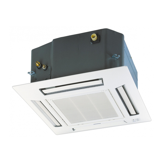
Indoor Unit
CS-Z25UB4EAW
CS-Z35UB4EAW
CS-Z50UB4EAW
CS-Z60UB4EAW
CU-5E34PBE,
CU-2Z35TBE,
CAUTION
Order No: PAPAMY1801009CE
Outdoor Unit
CU-Z25UBEA
CU-Z35UBEA
CU-Z50UBEA
CU-Z60UBEA
Destination
Europe
Turkey
CU-2Z41TBE,
CU-2Z50TBE,
in the Schematic
© Panasonic Corporation 2018.
Advertisement
Table of Contents

Related Manuals for Panasonic CS-Z25UB4EAW


Summary of Contents for Panasonic CS-Z25UB4EAW
- Page 1 – This Air Conditioner contains and operates with refrigerant R32. THIS PRODUCT MUST ONLY BE INSTALLED OR SERVICED BY QUALIFIED PERSONNEL. Refer to Commonwealth, State, Territory and local legislation, regulations, codes, installation & operation manuals, before the installation, maintenance and/or service of this product. © Panasonic Corporation 2018.
-
Page 2: Table Of Contents
Cooling operation ........77 Outdoor Unit ..........23 15.2 Soft Dry Operation ........77 7. Refrigeration Cycle Diagram ......25 15.3 Heating Operation ........77 CS-Z25UB4EAW CU-Z25UBEA 15.4 Automatic Operation ........78 CS-Z35UB4EAW CU-Z35UBEA ....25 15.5 Indoor Fan Motor Operation .......78 CS-Z50UB4EAW CU-Z50UBEA 15.6... -
Page 3: Safety Precautions
1. Safety Precautions Read the following “SAFETY PRECAUTIONS” carefully before perform any servicing. Electrical work must be installed or serviced by a licensed electrician. Be sure to use the correct rating of the power plug and main circuit for the model installed. ... - Page 4 WARNING Do not perform flare connection inside a building or dwelling or room, when joining the heat exchanger of indoor unit with interconnecting piping. Refrigerant connection inside a building or dwelling or room must be made by brazing or welding. Joint connection of indoor unit by flaring method can only be made at outdoor or at outside of a building or dwelling or room.
- Page 5 CAUTION Do not touch the sharp aluminium fin, sharp parts may cause injury. Carry out drainage piping as mentioned in installation instructions. If drainage is not perfect, water may enter the room and damage the furniture. Select an installation location which is easy for maintenance. Incorrect installation, service or repair of this air conditioner may increase the risk of rupture and this may result in loss damage or injury and/or property.
-
Page 6: Precaution For Using R32 Refrigerant
2. Precaution for Using R32 Refrigerant The basic installation work procedures are the same as conventional refrigerant (R410A, R22) models. However, pay careful attention to the following points: WARNING Since the working pressure is higher than that of refrigerant R22 models, some of the piping and installation and service tools are special. - Page 7 CAUTION 2-5. No ignition sources No person carrying out work in relation to a refrigeration system which involves exposing any pipe work that contains or has contained flammable refrigerant shall use any sources of ignition in such a manner that it may lead to the risk of fire or explosion. He/She must not be smoking when carrying out such work.
- Page 8 CAUTION Leak detection methods Electronic leak detectors shall be used to detect flammable refrigerants, but the sensitivity may not be adequate, or may need re- calibration. (Detection equipment shall be calibrated in a refrigerant-free area.) Ensure that the detector is not a potential source of ignition and is suitable for the refrigerant used. ...
- Page 9 CAUTION Labelling Equipment shall be labelled stating that it has been de-commissioned and emptied of refrigerant. The label shall be dated and signed. Ensure that there are labels on the equipment stating the equipment contains flammable refrigerant. Recovery ...
-
Page 10: Specifications
3. Specifications Indoor CS-Z25UB4EAW CS-Z35UB4EAW Model Outdoor CU-Z25UBEA CU-Z35UBEA Performance Test Condition EUROVENT EUROVENT Phase, Hz Single, 50 Single, 50 Power Supply Min. Mid. Max. Min. Mid. Max. 0.85 2.50 3.20 0.85 3.50 4.00 Capacity BTU/h 2900 8530 10900 2900... - Page 11 Indoor CS-Z25UB4EAW CS-Z35UB4EAW Model Outdoor CU-Z25UBEA CU-Z35UBEA Type Hermetic Motor (Rotary) Hermetic Motor (Rotary) Compressor Motor Type Brushless (6 poles) Brushless (6 poles) Output Power Type BACKWARD FAN BACKWARD FAN Material Motor Type DC / Transistor (8-poles) DC / Transistor (8-poles) Input Power –...
- Page 12 Indoor CS-Z25UB4EAW CS-Z35UB4EAW Model Outdoor CU-Z25UBEA CU-Z35UBEA Net (I/D / O/D / Weight kg (lb) 18 (40) / 33 (73) / 2.5 (6) 18 (40) / 35 (77) / 2.5 (6) PANEL) Pipe Diameter (Liquid / Gas) mm (inch) 6.35 (1/4) / 9.52 (3/8) 6.35 (1/4) / 9.52 (3/8)
- Page 13 Indoor CS-Z50UB4EAW CS-Z60UB4EAW Model Outdoor CU-Z50UBEA CU-Z60UBEA Performance Test Condition EUROVENT EUROVENT Phase, Hz Single, 50 Single, 50 Power Supply Min. Mid. Max. Min. Mid. Max. 0.90 5.00 5.80 0.90 6.00 6.35 Capacity BTU/h 3070 17100 19800 3070 20500 21700 Kcal/h 4300 4990...
- Page 14 Indoor CS-Z50UB4EAW CS-Z60UB4EAW Model Outdoor CU-Z50UBEA CU-Z60UBEA Type Hermetic Motor (Rotary) Hermetic Motor (Rotary) Compressor Motor Type Brushless (4 poles) Brushless (4 poles) Output Power Type BACKWARD FAN BACKWARD FAN Material Motor Type DC / Transistor (8-poles) DC / Transistor (8-poles) Input Power –...
- Page 15 Indoor CS-Z50UB4EAW CS-Z60UB4EAW Model Outdoor CU-Z50UBEA CU-Z60UBEA Net (I/D / O/D / Weight kg (lb) 18 (40) / 43 (95) / 2.5 (6) 18 (40) / 43 (95) / 2.5 (6) PANEL) Pipe Diameter (Liquid / Gas) mm (inch) 6.35 (1/4) / 12.70 (1/2) 6.35 (1/4) / 12.70 (1/2) Standard length m (ft)
- Page 16 (as shown in the table above) Example: The indoor units’ combination below is possible to connect to CU-3Z68TBE. (Total nominal capacity of indoor units is between 4.5kW to 11.2kW) 1) Two CS-Z25UB4EAW only. (Total nominal cooling capacity is 5.0kW)
- Page 17 (as shown in the table above) Example: The indoor units’ combination below is possible to connect to CU-4Z80TBE. (Total nominal capacity of indoor units is between 4.5kW to 14.7kW) 1) Two CS-Z25UB4EAW only. (Total nominal cooling capacity is 5.0kW)
- Page 18 Example: The indoor units’ combination below is possible to connect to CU-3E23SBE. (Total nominal capacity of indoor units is between 4.5kW to 11.0kW) 1) Two CS-Z25UB4EAW only. (Total nominal cooling capacity is 5.0kW) Note*: Above outdoor unit is contains and operates with refrigerant R410A gas.
- Page 19 Example: The indoor units’ combination below is possible to connect to CU-4E27PBE. (Total nominal capacity of indoor units is between 4.5kW to 13.6kW) 1) Two CS-Z25UB4EAW only. (Total nominal cooling capacity is 5.0kW) Note*: Above outdoor unit is contains and operates with refrigerant R410A gas.
-
Page 20: Features
4. Features Inverter Technology Wider output power range Energy saving Quick Cooling Quick Heating More precise temperature control Environment Protection Non-ozone depletion substances refrigerant (R32) Long Installation Piping Long piping up to 20 meters (1.0 ~ 1. 5HP) and 30 meters (2.0 ~ 2.25HP) during single split connection only ... -
Page 21: Location Of Controls And Components
5. Location of Controls and Components Indoor Unit Control Panel POWER (Green) Receiver TIMER (Orange) POWERFUL (Orange) QUIET (Orange) AUTO AIR SWING (Orange) Auto OFF/ON button Airflow direction louver Air filter Intake grille Outdoor Unit Remote Control LCD display OFF/ON Powerful operation Temperature setting Quiet operation... -
Page 22: Dimensions
6. Dimensions Indoor Unit Air Inlet <Remote Control> 530 (Hanging bolt) 650 (Ceiling opening) Gas piping Liquid piping Drain pipe <Remote Control Holder> Unit : mm... -
Page 23: Outdoor Unit
Outdoor Unit 6.2.1 CU-Z25UBEA <Top View> Space necessary for installation 67.6 (104.7) 570.3 104.9 60.5 100 mm 100 mm 1000 mm 2-way valve at Liquid side Anchor Bolt Pitch (High Pressure) × 3-way valve at Gas side (Low Pressure) <Side View> <Side View>... - Page 24 6.2.3 CU-Z50UBEA CU-Z60UBEA <Top View> Space necessary for installation (131) 34.7 100 mm 100 mm 1000 mm Anchor Bolt Pitch 360.5 × 613 2-way valve at Liquid side (High Pressure) 3-way valve at Gas side (Low Pressure) <Front View> <Side View> <Side View>...
-
Page 25: Refrigeration Cycle Diagram
7. Refrigeration Cycle Diagram CS-Z25UB4EAW CU-Z25UBEA CS-Z35UB4EAW CU-Z35UBEA INDOOR OUTDOOR LIQUID EXPANSION TEMP. SIDE VALVE STRAINER STRAINER SENSOR 2-WAY VALVE PIPE TEMP. INTAKE SENSOR 2 TEMP. SENSOR CONDENSER PIPE TEMP. PIPE SENSOR 1 TEMP. SENSOR HEAT EXCHANGER (EVAPORATOR) SIDE MUFFLER... -
Page 26: Cs-Z50Ub4Eaw Cu-Z50Ubea Cs-Z60Ub4Eaw Cu-Z60Ubea
CS-Z50UB4EAW CU-Z50UBEA CS-Z60UB4EAW CU-Z60UBEA INDOOR OUTDOOR LIQUID EXPANSION SIDE STRAINER VALVE 2-WAY PROCESS VALVE TUBE TEMP. PIPE SENSOR TEMP. CONDENSER INTAKE SENSOR 2 TEMP. SENSOR PIPE TEMP. PIPE SENSOR 1 TEMP. SENSOR HEAT EXCHANGER (EVAPORATOR) SIDE 4-WAYS VALVE 3-WAY RECEIVER VALVE TANK SENSOR... -
Page 27: Block Diagram
8. Block Diagram CS-Z25UB4EAW CU-Z25UBEA CS-Z35UB4EAW CU-Z35UBEA... -
Page 28: Cs-Z50Ub4Eaw Cu-Z50Ubea Cs-Z60Ub4Eaw Cu-Z60Ubea
CS-Z50UB4EAW CU-Z50UBEA CS-Z60UB4EAW CU-Z60UBEA... -
Page 29: Wiring Connection Diagram
9. Wiring Connection Diagram Indoor Unit... -
Page 30: Outdoor Unit
Outdoor Unit 9.2.1 CU-Z25UBEA CU-Z35UBEA YELLOW (YEL) OR T(W) REMARKS BLU : BLUE BLK : BLACK SINGLE PHASE POWER SUPPLY TO INDOOR UNIT WHT : WHITE RED : RED BLUE YLW : YELLOW (RED) (BLU) GRY : GRAY OR R(U) OR S(V) GRN : GREEN TERMINAL... - Page 31 9.2.2 CU-Z50UBEA CU-Z60UBEA YELLOW (YLW) OR (C) REMARKS BLU: BLUE BLK: BLACK TO INDOOR UNIT SINGLE PHASE BLUE (BLK) (WHT) (RED) WHT: WHITE POWER SUPPLY (BLU) (RED) RED: RED OR (R) OR (S) YLW: YELLOW GRY: GRAY TERMINAL (TRADEMARK) REACTOR BOARD GRN: GREEN COMPERSSOR TERMINAL...
-
Page 32: Electronic Circuit Diagram
10. Electronic Circuit Diagram 10.1 Indoor Unit TRANSFORMER MOTOR HAJEM-A (WHT) R42 R43 HIGH STATIC PRESSURE MOTOR CN-FM (FAN) ELECTRONIC CONTROLLER (MAIN) (WHT) SW01 CN-T2 CN-CNT CN-STM2 CN-T1 (YLW) (WHT) (YLW) (WHT) RECTIFICATION CIRCUIT CN-STM1 IC05 IC07 RECTIFICATION RECTIFICATION (WHT) CIRCUIT CIRCUIT *C57... -
Page 33: Outdoor Unit
10.2 Outdoor Unit 10.2.1 CU-Z25UBEA CU-Z35UBEA REACTOR RAT1 RAT2 (GRY) (GRY) 15.8k 220u SINGLE PHASE POWER SUPPLY TO INDOOR UNIT OUTDOOR AIR TEMP. SENSOR (THERMISTOR) t° TERMINAL CN–TH1 t° BOARD (WHT) PIPING TEMP. SENSOR (THERMISTOR) DATA t° (RED) COMMUNICATION COMPRESSOR TEMP. SENSOR (THERMISTOR) CN–TANK CIRCUIT 4.99k... - Page 34 10.2.2 CU-Z50UBEA CU-Z60UBEA TO INDOOR UNIT SINGLE PHASE (BLK) (WHT) (RED) POWER SUPPLY TERMINAL BOARD REACTOR RAT2 RAT1 DATA (GRY) (GRY) (RED) COMMUNICATION NOISE FILTER CIRCUIT FUSE 5 AC-BLK CIRCUIT 15.8k (20A 250V) (BLK) 470u FUSE 1 (25A 250V) FUSE 6 FUSE 8 OUTDOOR AIR TEMP.
-
Page 35: Printed Circuit Board
11. Printed Circuit Board 11.1 Indoor Unit 11.1.1 Main Printed Circuit Board CN-DRMTR1 CN-T2 CN-T1 T-BLK1 T-BLK2 SW01 SW02 CN-CNT CN-FM CN-TH1 CN-TH2 CN-STM1 (Random Auto Restart enable/disable) CN-STM2 HAJEM-A 11.1.2 Display Printed Circuit Board CN-DISP... -
Page 36: Outdoor Unit
11.2 Outdoor Unit 11.2.1 Main Printed Circuit Board 11.2.1.1 CU-Z25UBEA CU-Z35UBEA POWER TRANSISTOR (IPM) CN-MTR2 CN-MTR1 CN-TH1 CN-DEMAND CN-TANK CN-HOT CN-STM AC-WHT DATA CURRENT TRANSFORMER (CT) AC-BLK CN-V1... - Page 37 11.2.1.2 CU-Z50UBEA CU-Z60UBEA POWER TRANSISTOR (IPM) CN-MTR2 CURRENT TRANSFORMER (CT) CN-MTR1 CN-STM1 CN-TH1 CN-HOT DATA CN-TANK AC-WHT AC-BLK...
-
Page 38: Installation Instruction
12. Installation Instruction 12.1 Indoor Unit Required Materials 12.1.1 Indoor Installation Diagram Read the catalog and other technical materials and prepare the required materials. Installation parts you Applicable piping kit should purchase ( ) Sleeve ( ) Piping size Bushing-Sleeve ( ) Applicable piping kit Putty (Gum Type... - Page 39 12.1.2 Selecting the Location for the Indoor Unit Provide a check port on the piping side ceiling for repair and maintenance. Install the indoor unit once the following conditions are satisfied and after receiving the customer approval. The indoor unit must be within a maintenance space. The indoor unit must be free from any obstacles in path of the air inlet and outlet, and must allow spreading of air throughout the room.
- Page 40 12.1.3 Installation of Indoor Unit This air conditioner uses a drain up motor. (Unit: mm) 650 (Ceiling opening) Drain pipe Horizontally install the unit using a level gauge. (Hanging bolt) CEILING OPENING DIMENSIONS AND HANGING BOLT LOCATION The paper model for installation expand or shrink 580 (Unit size) according to temperature and humidity.
- Page 41 Do not overtighten, overtightening may cause gas leakage. Vacuum drying Piping size Torque After completing the piping connection, execute 6.35 mm (1/4") [18 N•m (1.8 kgf•cm)] vacuum drying for the connecting piping and the indoor unit. 9.52 mm (3/8") [42 N•m (4.3 kgf•cm)] The vacuum drying must be carried out by using the 12.7 mm (1/2") [55 N•m (5.6 kgf•cm)]...
- Page 42 12.1.6 Heat Insulation Be sure to perform heat insulation on the drain, liquid and gas piping. Imperfection in heat insulation Caution work leads to water leakage. Use the heat insulation material for the refrigerant piping which has an excellent heat-resistance (over 120°C). Hose clip (Accessory) Overlap with heat insulator for piping.
- Page 43 12.1.7.1 Wire Stripping and Connection Requirement Conductor not Conductor Conductor Wire stripping fully inserted Indoor/outdoor fully inserted over inserted connection terminal board 5 mm or more No loose strand when inserted ACCEPT PROHIBITED PROHIBITED (gap between wires) RISK OF FIRE JOINING OF WIRES M AY CAUSE WARNING OVERHE ATING AND FIRE.
- Page 44 Fit the decorative panel and ceiling wall together and confirm no gap in between. Readjust indoor unit height, if there is a gap between ceiling wall and decorative panel. Good example Bad example Air conditioner Air conditioner unit Cool air leakage unit (no good) Ceiling...
- Page 45 12.1.9.3 Connecting The Piping to Outdoor Multi Decide piping length and then cut by using pipe cutter. Remove burrs from cut edge. Make flare after inserting the flare nut (locate at valve) onto the copper pipe. Align center of piping to valve and then tighten with torque wrench to the specified torque as stated in the table.
-
Page 46: Outdoor Unit
12.2 Outdoor Unit 12.2.1 Select the Best Location 12.2.1.1 Outdoor Installation Diagram If an awning is built over the unit to prevent direct sunlight or rain, be careful that heat radiation from the condenser is not obstructed. There should not be any animal or plant which Power supply cable ( ) could be affected by hot air discharged. - Page 47 12.2.3 Connect the Piping 12.2.3.1 Connecting the Piping to Indoor For connection joint location at outside building For connection joint location at inside building Please make flare after inserting flare nut (locate at Refer to indoor installation instruction. joint portion of tube assembly) onto the copper pipe. (In case of using long piping) Connect the piping ...
- Page 48 Remove the valve caps of both of the 2-way valve and 3-way valve. Position both of the valves to “OPEN” using a hexagonal wrench (4 mm). Mount valve caps onto the 2-way valve and the 3-way valve. Be sure to check for gas leakage. ...
- Page 49 12.2.6.1 Cutting and Flaring the Piping Please cut using pipe cutter and then remove the burrs. Remove the burrs by using reamer. If burrs is not removed, gas leakage may be caused. Turn the piping end down to avoid the metal powder entering the pipe. Please make flare after inserting the flare nut onto the copper pipes.
-
Page 50: Installation And Servicing Air Conditioner Using R32
13. Installation and Servicing Air Conditioner using R32 13.1 About R32 Refrigerant For air conditioning refrigerants such as R410A, the refrigerants were collected back in order to prevent their air dissipation, to curbe the global warming impact, in case they were released into the atmosphere. In the “4th Environmental Basic Plan”, 80% reduction of greenhouse gas emissions by 2050 is required, and due to this requirement, further reduction in the emission of high greenhouse effect gas, such as CFCs, is required. - Page 51 2. Characteristic of Pressure As shown in Table 2, R32 does not have much difference in vapor pressure at the same refrigerant temperature comparing to R410A, but comparing to R22, it is higher at 1.6 times more. Thus, the same as in case of R410A, it is necessary to do installation and service using high-pressure tools and components.
-
Page 52: Refrigerant Piping Installation • Tools Used In Services
13.3 Refrigerant piping installation • Tools used in services 13.3.1 Required Tools R32 refrigerant air conditioners use the common parts as R410A air conditioners for two-way valves and three-way valves (diameters of service ports); thus, they maintain commonality in the maintenance of the compressive strength, the size of pipe flaring, and the size of flare nuts as R410A. - Page 53 3. Torque wrenches (diameters 1/2, 5/8) Manifold gauges / Charging hoses In order to strengthen the compressive strength, the diameters of wrenches change depending on the flare nut sizes. Torque wrenches Differences in charging hoses Differences in torque wrenches (common R410A) Normal 5.1 MPa 3.4 MPa...
- Page 54 7. HFC refrigerant_Electric gas leakage tester 9. Refrigerant cylinders R32 refrigerant is often used for other mixed Refrigerant cylinders for R410A are painted in pink, refrigerant (R410A, R404A, R407C etc.). Therefore, and the ones for R32 are painted in other colors that the usage of existing HFC detectors is possible, but in might subject to change according to the international order to detect more accurately, we recommend to...
- Page 55 11. Tools used for refrigerant piping installations and services Tools for R410A Common with R32 Possibility of usage for R22 ○ ○ Pipe cutters, reamers or scrapers ○ ○ Flare tools (clutch type) ○ ○ Torque wrench (1/4, 3/8) ○ ×...
-
Page 56: New Installation, Relocation, Repairing Of Refrigerant Cycle System The Procedures
13.4 New installation, Relocation, Repairing of Refrigerant Cycle System The Procedures Relocation Repairing refrigerant cycle Installation Indoor / outdoor units and piping Pump down Refrigerant recovery • Displacing pipes and wires, and displacing indoor / outdoor units Prevention of impurity •... -
Page 57: Piping Installation Of R32
13.5 Piping installation of R32 13.5.1 Pipe materials used and flaring Copper pipes are used for refrigerant piping. Pipes Pipe thickness which comply with JIS Regulations need to be used. Room air conditioners which use R410A and R32 O and OL materials Thickness (mm) have higher pressure;... -
Page 58: Installation, Relocation, And Service
13.6 Installation, Relocation, and Service 13.6.1 Air purge and gas leak test for new installation (using new refrigerant pipes) using vacuum pump (From the point of view of global environment protection, do not release CFCs into the atmosphere during installation work) 1. - Page 59 13.6.2 Process of refrigerant recovery 1. Connect the center charging hose of manifold gauge to the in-let side of recovery device. 2. Connect the valves of the discharge side of recovery device and liquid side of refrigerant cylinder with red hose (charging hose).
- Page 60 13.6.3 Relocation 1. Removing the air conditioning unit a) Recovery of outdoor unit refrigerant by pumping down Press “forced cooling button” (as a general rule, since 1998 the name of cooling testing button is changed, and this name is unified within the air conditioning industry), and then you are able to start cooling operation in which the room temperature is low, and you can recover the refrigerant from the outdoor unit.
- Page 61 13.6.6 Re-insertion of refrigerant in service When re-insertion is needed, follow the procedures to ensure the insertion of new refrigerant at correct amount. 1. Attach charging hose (blue) to the service port of the outdoor unit. 2. Attach charging hose (red) to the vacuum pump. Fully open the 2-way and 3-way valves. 3.
-
Page 62: Repairing Of Refrigerant Cycle / Brazing Point
13.7 Repairing of refrigerant cycle / Brazing point 13.7.1 Preparation for repairing of refrigerant cycle / brazing Brazing which is a technique needed for repairing refrigerant cycle requires advanced technique and experience, and this brazing procedure can only be performed by the workers who completed “Gas Welding Skill Training” regulated by the Occupational Safety and Health Act, and went through the training programs of refrigerant operations. - Page 63 2. Cylinder without adjustment valve side gauge pressure is adjusted by the adjuster. Check the both side valves of the torch and open the cylinder valve to check the remaining refrigerant in the cylinder. Caution: Do not attach oil component on the connection port of the adjuster. Especially, use an oxygen cylinder adjuster which is no oil substance type.
- Page 64 13.7.5 Types of flame Types of flame change based on the proportion of propane and oxygen. [Neutral Flame] Perform brazing with this flame (This is a flame when oxygen and propane are mixed at proper proportion, and has lesser effect on the brazed metals) White core flame 10 ~ 15 mm...
- Page 65 13.7.7 Selection of brazing material Use BAg brazing material (silver solder) to increase the welding performance. Tensile strength Composition of ingredients (%) Temperature (°C) Characteristics (Reference) Category Standard Brazing Base Number Solidus Liquidus Kgf•cm applications temp material Liquidity is good at low temperature, 49.0 14.5...
- Page 66 13.7.10 Checking of brazing (insert) points 1. No impurity on the brazing point Gap 0.025 ~ 0.05 mm If dirt or oil is attached on the brazing point, the brazing filler metal does not reach to junction, and Inner diameter ø6.45 it may cause poor welding.
- Page 67 (Reference) Melting temperature of copper • • • • • • • Approx. 1083°C Maximum temperature obtained in propane and oxygen • • • • • • • Approx. 1083°C The important point is to heat the bonding part uniformly within a short period of time until reaching to the brazing temperature in the following manner.
-
Page 68: Reference> Analysis Method For No Error Code, No Cooling / No Warming
13.8 <Reference> Analysis method for no error code, no cooling / no warming 13.8.1 Preparation for appropriate diagnosis In order to obtain appropriate operation characteristics, minimum 15 minutes or more operation time [testing operation (rated operation)] is required. 1. Method of rated operation (rated operation) For the models which have two buttons of “emergency operation and forced cooling operation”, press forced cooling button once. - Page 69 1. Measuring temperature 1) Indoor unit suction temperature, release temperature, temperature difference, → Measure by thermometer 2) 2-way valve pipe temperature in cooling mode is low temperature (benchmark:5 ~ 10°C), in heating mode is medium temperature (benchmark:25 ~ 35°C). 3) 3-way valve pipe temperature in cooling mode is low temperature (benchmark:7 ~ 15°C) in heating mode is high temperature (benchmark:38 ~ 50°C).
-
Page 70: Operation Control
14. Operation Control 14.1 Basic Function Inverter control, which equipped with a microcomputer in determining the most suitable operating mode as time passes, automatically adjusts output power for maximum comfort always. In order to achieve the suitable operating mode, the microcomputer maintains the set temperature by measuring the temperature of the environment and performing temperature shifting. -
Page 71: Indoor Fan Motor Operation
14.1.5 Automatic Operation This mode can be set using remote control and the operation is decided by remote control setting temperature, remote control operation mode and indoor intake air temperature. During operation mode judgment, indoor fan motor (with speed of Lo-) is running for 30 seconds to detect the indoor intake air temperature. -
Page 72: Outdoor Fan Motor Operation
[Heating] According to indoor pipe temperature, automatic heating fan speed is determined as follows. RPM Increased RPM Maintain RPM Reduced Indoor Pipe Temp. B. Feedback control Immediately after the fan motor started, feedback control is performed once every second. ... -
Page 73: Airflow Direction
14.4 Airflow Direction There is one type of airflow, vertical airflow (directed by horizontal vane). Control of airflow direction can be automatic (angles of direction is determined by operation mode, heat exchanger temperature and intake air temperature) and manual (angles of direction can be adjusted using remote control). -
Page 74: Quiet Operation (Heating)
14.6 Quiet Operation (Heating) Purpose To provide quiet heating operation compare to normal operation. Control condition Quiet operation start condition When “QUIET” button at remote control is pressed. QUIET LED illuminates. Quiet operation stop condition When one of the following conditions is satisfied, quiet operation stops: ... -
Page 75: Auto Restart Control
14.9 Auto Restart Control When the power supply is cut off during the operation of air conditioner, the compressor will re-operate within three to four minutes (there are 10 patterns between 2 minutes 58 seconds and 3 minutes 52 seconds to be selected randomly) after power supply resumes. - Page 76 Condition 1-2 (Pulse input): Unit ON/OFF condition switching with a pulse signal. (1 pulse signal: shortage status 200~300msec) 3-4 (Static output): 5V output during the unit ON. No output at OFF. Example of wiring: Core 240 mm HAJEM-A Indoor Unit (XH type) Max 1900 mm #A K1KA04AA0347 (Maker: JST;...
-
Page 77: Operation Control (For Multi Split Connection)
15. Operation Control (For Multi Split Connection) During multi split connection, indoor unit’s operation controls are same with single split connection unless specified in this chapter. 15.1 Cooling operation 15.1.1 Thermostat control Capability supply to indoor unit is OFF (Expansion valve closed) when Intake Air Temperature — Internal setting temperature <... -
Page 78: Automatic Operation
15.4 Automatic Operation This mode can be set using remote control and the operation is decided by remote control setting temperature, remote control operation mode, indoor intake and outdoor air temperature. During operation mode judgment, indoor fan motor (with speed of -Lo) and outdoor fan motor are running for 30 seconds to detect the indoor intake and outdoor air temperature. -
Page 79: Protection Control
16. Protection Control 16.1 Protection Control for All Operations 16.1.1 Restart Control (Time Delay Safety Control) The Compressor will not turn on within 3 minutes from the moment operation stops, although the unit is turned on again by pressing OFF/ON button at remote control within this period. ... - Page 80 16.1.4 Compressor Overheating Prevention Control Instructed frequency for compressor operation will be regulated by compressor temperature. The changes of frequency are as below. If compressor temperature exceeds 103°C, compressor will be stopped, occurs 4 times per 20 minutes, timer LED will be blinking.
-
Page 81: Protection Control For Cooling & Soft Dry Operation
16.2 Protection Control for Cooling & Soft Dry Operation 16.2.1 Outdoor Air Temperature Control The compressor operating frequency is regulated in accordance to the outdoor air temperature as shown in the diagram below. This control will begin 1 minute after the compressor starts. ... -
Page 82: Protection Control For Heating Operation
16.2.5 Dew Prevention Control 1 To prevent dew formation at indoor unit discharge area. This control will be activated if: Outdoor air temperature and Indoor pipe temperature judgment by microcontroller is fulfilled. When Cooling or Dry mode is operated more than 20 minutes or more. ... - Page 83 16.3.4 Low Temperature Compressor Oil Return Control In heating operation, if the outdoor temperature falls below -10°C when compressor starts, the compressor frequency will be regulated up to 600 seconds. 16.3.5 Cold Draught Prevention Control When indoor pipe temperature is low, cold draught operation starts where indoor fan speed will be reduced. 16.3.6 Deice Operation ...
-
Page 84: Servicing Mode
17. Servicing Mode 17.1 Auto OFF/ON Button Auto OFF/ON Auto OFF/ON Auto OFF/ON Auto OFF/ON Button pressed Button pressed Button pressed Button pressed 5 sec 5 sec 5 sec Auto Operation Test Run Operation Stop Normal Cooling Operation Stop Test Run Operation Stop (Forced cooling operation) (Forced heating operation) -
Page 85: Heat Only Operation
REMOTE CONTROL RECEIVING SOUND OFF/ON MODE The Remote Control Receiving Sound OFF/ON Mode will be activated if the Auto OFF/ON button is pressed continuously for more than 16 seconds (4 “beep” sounds will occur at 16th seconds to identify the Remote Control Receiving Sound Off/On Mode is in standby condition) and press “AC Reset”... -
Page 86: Remote Control Button
17.2.2 Operation mode during Heating Only Operation The table below shows the operation mode comparison when Heating Only Operation Mode Activated and Deactivated. Operation Mode Heating Only Operation Mode Activated Heating Only Operation Mode Deactivated After 30s sampling, the unit will judge the operation After 30s sampling, regardless of the indoor intake or mode base on remote controller temperature setting AUTO... - Page 87 17.3.2 RESET (RC) To clear and restore the remote control setting to factory default. Press once to clear the memory. 17.3.3 RESET (AC) To restore the unit’s setting to factory default. Press once to restore the unit’s setting. 17.3.4 TIMER ▲...
- Page 88 To enter zone 1 area: Normal display Enter Zone1 mode [range (1~49)] To enter zone 2 area: (Press continuously for T ≥ 5 secs) Once T ≥ 5secs Normal display Enter Zone1 Enter Zone2 mode [range (50~99)]...
- Page 89 Function & Options list: Note: The functions described in the table may not be applicable to the model and may subject to change without further notice. Function Options Remark Name Remote control number selection A, B, C, D Solar radiation sensitivity level adjustment 1, 2, 3, 4, 5 [iAUTO-X/iAUTO/iCOMF, Cool &...
-
Page 90: Troubleshooting Guide
18. Troubleshooting Guide 18.1 Refrigeration Cycle System In order to diagnose malfunctions, make sure that there are no Normal Pressure and Outlet Air Temperature (Standard) electrical problems before inspecting the refrigeration cycle. Gas Pressure Outlet air Temperature Such problems include insufficient insulation, problem with the (kg/cm (°C) power source, malfunction of a compressor and a fan. - Page 91 18.1.1 Relationship Between the Condition of the Air Conditioner and Pressure and Electric Current Cooling Mode Heating Mode Condition of the Electric current Electric current air conditioner Low Pressure High Pressure Low Pressure High Pressure during operation during operation Insufficient refrigerant ...
-
Page 92: Breakdown Self Diagnosis Function
18.2 Breakdown Self Diagnosis Function 18.2.1 Self Diagnosis Function (Three Digits Alphanumeric Code) When the latest abnormality code on the main Once abnormality has occurred during operation, unit and code transmitted from the remote the unit will stop its operation, and Timer LED controller are matched, power LED will light blinks. -
Page 93: Error Codes Table
18.3 Error Codes Table Diagnosis Abnormality / Abnormality Protection Problem Check location display Protection control Judgment Operation No memory of failure — Normal operation — — Indoor fan only Indoor/outdoor wire terminal Indoor/outdoor operation can Indoor/outdoor After operation for ... - Page 94 Diagnosis Abnormality / Abnormality Protection Problem Check location display Protection control Judgment Operation Check indoor/outdoor Wrong wiring and connection wire and connection Abnormal wiring or — — connecting pipe, expansion pipe piping connection valve abnormality Expansion valve and lead wire and connector Outdoor high High pressure sensor open...
-
Page 95: Self-Diagnosis Method
18.4 Self-diagnosis Method 18.4.1 H11 (Indoor/Outdoor Abnormal Communication) Malfunction Decision Conditions During startup and operation of cooling and heating, the data received from outdoor unit in indoor unit signal transmission is checked whether it is normal. Malfunction Caused Faulty indoor unit PCB. - Page 96 18.4.2 H12 (Indoor/Outdoor Capacity Rank Mismatched) Malfunction Decision Conditions During startup, error code appears when different types of indoor and outdoor units are interconnected. Malfunction Caused Wrong models interconnected. Wrong indoor unit or outdoor unit PCBs mounted. ...
- Page 97 18.4.3 H14 (Indoor Intake Air Temperature Sensor Abnormality) Malfunction Decision Conditions During startup and operation of cooling and heating, the temperatures detected by the indoor intake air temperature sensor are used to determine sensor errors. Malfunction Caused Faulty connector connection. ...
- Page 98 18.4.4 H15 (Compressor Temperature Sensor Abnormality) Malfunction Decision Conditions During startup and operation of cooling and heating, the temperatures detected by the outdoor compressor temperature sensor are used to determine sensor errors. Malfunction Caused Faulty connector connection. Faulty sensor.
- Page 99 18.4.5 H16 (Outdoor Current Transformer) Malfunction Decision Conditions An input current, detected by Current Transformer CT, is below threshold value when the compressor is operating at certain frequency value for 3 minutes. Malfunction Caused Lack of gas Broken CT (current transformer) ...
- Page 100 18.4.6 H19 (Indoor Fan Motor – DC Motor Mechanism Locked) Malfunction Decision Conditions The rotation speed detected by the Hall IC during fan motor operation is used to determine abnormal fan motor (feedback of rotation > 2550 rpm or < 50 rpm) Malfunction Caused ...
- Page 101 18.4.7 H23 (Indoor Pipe Temperature Sensor Abnormality) Malfunction Decision Conditions During startup and operation of cooling and heating, the temperatures detected by the indoor heat exchanger temperature sensor are used to determine sensor errors. Malfunction Caused Faulty connector connection. ...
- Page 102 18.4.8 H24 (Indoor Pipe Temperature Sensor 2 Abnormality) Malfunction Decision Conditions During startup and operation of cooling and heating, the temperatures detected by the indoor heat exchanger temperature sensor 2 are used to determine sensor errors. Malfunction Caused Faulty connector connection.
- Page 103 18.4.9 H27 (Outdoor Air Temperature Sensor Abnormality) Malfunction Decision Conditions During startup and operation of cooling and heating, the temperatures detected by the outdoor air temperature sensor are used to determine sensor errors. Malfunction Caused Faulty connector connection. ...
- Page 104 18.4.10 H28 (Outdoor Pipe Temperature Sensor Abnormality) Malfunction Decision Conditions During startup and operation of cooling and heating, the temperatures detected by the outdoor pipe temperature sensor are used to determine sensor errors. Malfunction Caused Faulty connector connection. ...
- Page 105 18.4.11 H30 (Compressor Discharge Temperature Sensor Abnormality) Malfunction Decision Conditions During startup and operation of cooling and heating, the temperatures detected by the outdoor discharge pipe temperature sensor are used to determine sensor errors. Malfunction Caused Faulty connector connection. ...
- Page 106 18.4.12 H32 (Outdoor Heat Exchanger Temperature Sensor 2 Abnormality) Malfunction Decision Conditions During startup and operation of cooling and heating, the temperatures detected by the outdoor heat exchanger temperature sensor are used to determine sensor errors. Malfunction Caused Faulty connector connection.
- Page 107 18.4.13 H33 (Unspecified Voltage between Indoor and Outdoor) Malfunction Decision Conditions The supply power is detected for its requirement by the indoor/outdoor transmission. Malfunction Caused Wrong models interconnected. Wrong indoor unit and outdoor unit PCBs used. Indoor unit or outdoor unit PCB defective.
- Page 108 18.4.14 H36 (Outdoor Gas Pipe Sensor Abnormality) Malfunction Decision Conditions During startup and operation of cooling and heating, the temperatures detected by the outdoor gas pipe temperature sensor are used to determine sensor errors. Malfunction Caused Faulty connector connection. ...
- Page 109 18.4.15 H37 (Outdoor Liquid Pipe Temperature Sensor Abnormality) Malfunction Decision Conditions During startup and operation of cooling and heating, the temperatures detected by the outdoor liquid pipe temperature sensor are used to determine sensor errors. Malfunction Caused Faulty connector connection. ...
- Page 110 18.4.16 H97 (Outdoor Fan Motor – DC Motor Mechanism Locked) Malfunction Decision Conditions The rotation speed detected by the Hall IC during fan motor operation is used to determine abnormal fan motor. Malfunction Caused Operation stops due to short circuit inside the fan motor winding. ...
- Page 111 18.4.17 H98 (Error Code Stored in Memory and no alarm is triggered / no TIMER LED flashing) Malfunction Decision Conditions Indoor high pressure is detected when indoor heat exchanger is detecting very high temperature when the unit is operating in heating operation. ...
- Page 112 18.4.18 H99 (Indoor Freeze Prevention Protection: Cooling or Soft Dry) Error Code will not display (no Timer LED blinking) but store in EEPROM Malfunction Decision Conditions Freeze prevention control takes place (when indoor pipe temperature is lower than 2°C) Malfunction Caused ...
- Page 113 18.4.19 F11 (4-way Valve Switching Failure) Malfunction Decision Conditions When indoor heat exchanger is cold during heating (except deice) or when indoor heat exchanger is hot during cooling and compressor operating, the 4-way valve is detected as malfunction. Malfunction Caused ...
- Page 114 18.4.20 F17 (Indoor Standby Units Freezing Abnormality) Malfunction Decision Conditions When the different between indoor intake air temperature and indoor pipe temperature is above 10°C or indoor pipe temperature is below -1.0°C. Remark: When the indoor standby unit is freezing, the outdoor unit transfers F17 error code to the corresponding indoor unit and H39 to other indoor unit(s).
- Page 115 18.4.21 F90 (Power Factor Correction Protection) Malfunction Decision Conditions To maintain DC voltage level supply to power transistor. To detect high DC voltage level after rectification. Malfunction Caused During startup and operation of cooling and heating, when Power Factor Correction (PFC) protection circuitry at the outdoor unit main PCB senses abnormal DC voltage level for power transistors.
- Page 116 18.4.22 F91 (Refrigeration Cycle Abnormality) Malfunction Decision Conditions The input current is low while the compressor is running at higher than the setting frequency. Malfunction Caused Lack of gas. 3-way valve close. Troubleshooting...
- Page 117 18.4.23 F93 (Compressor Rotation Failure) Malfunction Decision Conditions A compressor rotation failure is detected by checking the compressor running condition through the position detection circuit. Malfunction Caused Compressor terminal disconnect Faulty Outdoor PCB Faulty compressor Troubleshooting...
- Page 118 18.4.24 F95 (Outdoor High Pressure Protection: Cooling or Soft Dry) Malfunction Decision Conditions During operation of cooling or soft dry, when outdoor unit heat exchanger high temperature data is detected by the outdoor unit heat exchanger thermistor. Malfunction Caused ...
- Page 119 18.4.25 F96 (IPM Overheating) Malfunction Decision Conditions During operating of cooling and heating, when IPM temperature data (100°C) is detected by the IPM temperature sensor. Multi Models only Compressor Overheating: During operation of cooling and heating, when the compressor OL is activated. Heat Sink Overheating: During operation of cooling and heating, when heat sink temperature data (90°C) is detected by the heat sink temperature sensor.
- Page 120 18.4.26 F97 (Compressor Overheating) Malfunction Decision Conditions During operation of cooling and heating, when compressor tank temperature data (112°C) is detected by the compressor tank temperature sensor. Malfunction Caused Faulty compressor tank temperature sensor 2/3 way valve closed ...
- Page 121 18.4.27 F98 (Input Over Current Detection) Malfunction Decision Conditions During operation of cooling and heating, when an input over-current (X value in Total Running Current Control) is detected by checking the input current value being detected by current transformer (CT) with the compressor running.
- Page 122 18.4.28 F99 (DC Peak Detection) Malfunction Decision Conditions During startup and operation of cooling and heating, when inverter DC peak data is received by the outdoor internal DC Peak sensing circuitry. Malfunction Caused DC current peak due to compressor failure. ...
-
Page 123: Disassembly And Assembly Instructions
19. Disassembly and Assembly Instructions WARNING High Voltage is generated in the electrical parts area by the capacitor. Ensure that the capacitor has discharged sufficiently before proceeding with repair work. Failure to heed this caution may result in electric shocks. 19.1 Disassembly of Parts Front Grille Intake Grille... - Page 124 Hooks To remove the Electronic Controller, release the 6 hooks that hold it to the Control Board (Fig. 4). Electronic Controller Fig. 4 Remove the Front Grille by removing the Screw B Front Grille Screw C screw A and screws B, C & D half way open (Fig.
- Page 125 Remove the Fan Motor by release the Fan Motor lead wire connectors and Fan Motor screws (Fig. 8). Screws Connectors Fig. 8...
-
Page 126: Outdoor Electronic Controller Removal Procedure
19.2 Outdoor Electronic Controller Removal Procedure 19.2.1 CU-Z25UBEA Caution! When handling electronic controller, be careful of electrostatic discharge. Remove the 5 screws of the Top Panel. Remove the Control Board as follows: Screws Top Panel Release 3 Terminal Screws Connectors, L, N and Earth Wire Screw. - Page 127 19.2.2 CU-Z35UBEA Caution! When handling electronic controller, be careful of electrostatic discharge. Remove the 5 screws of the Top Panel. Remove the Control Board as follows: Fig. 4 Fig. 1 Remove the 8 screws of the Front Panel. Fig. 2 Fig.
- Page 128 19.2.3 CU-Z50UBEA CU-Z60UBEA Caution! When handling electronic controller, be careful of electrostatic discharge. Remove the 5 screws of the Top Panel. Remove 2 screws for the plate of Terminal Board Cover. Top Panel Screw Plate of Terminal Board Cover Screws Screws Screws Fig.
-
Page 129: Technical Data
20.1 Cool Mode Performance Data Unit setting: Standard piping length, Hi Fan, Cool mode at 16°C Voltage: 230V 20.1.1 CS-Z25UB4EAW CU-Z25UBEA Indoor (°C) Outdoor DB (°C) 19.0 3208 2206 435 3003 2800 396 2973 2785 399 3008 2904 383 3331 3085 333 2929 2754 436 2500 2462 550 22.0 3252 2227 387 3217 2173 425 3254 2213 416 3310 2246 390 3674 2483 324 3208 2206 435 2897 2046 560... - Page 130 20.1.4 CS-Z60UB4EAW CU-Z60UBEA Indoor (°C) Outdoor DB (°C) 19.0 7434 3597 1590 6960 4567 1447 6889 4543 1459 6971 4737 1401 7720 5032 1217 6788 4492 1594 6000 4159 2050 22.0 7537 3632 1415 7457 3543 1553 7541 3610 1521 7671 3664 1426 8514 4049 1185 7434 3597 1590 6713 3337 2048 15.7 6248 4540 1493 5977 4383 1624 6151 4482 1535 5937 4391 1680 5803 3782 1217 5589 3699 1599 5574 3864 2018 18.4 5725 3301 964 6701 3625 1590 6765 3678 1569 6963 3751 1452 6577 3617 907 5893 3247 1256 5855 3214 2041 13.3 4803 3868 766 4821 3936 980 4532 3817 1118 4842 3952 987 5019 3960 851 4098 2230 1574 4035 2797 1910...
-
Page 131: Heat Mode Performance Data
20.2 Heat Mode Performance Data Unit setting: Standard piping length, Hi Fan, Heat mode at 30°C Voltage: 230V 20.2.1 CS-Z25UB4EAW CU-Z25UBEA Indoor (°C) Outdoor WB (°C) 2191 1099 2848 1203 3330 1188 2986 3232 2335 1092 2880 1190 3480 1170... -
Page 132: Service Data
Condition Indoor room temperature: 27°C Dry Bulb/19°C Wet Bulb Unit setting: Standard piping length, forced cooling at 16°C, Hi fan Compressor frequency: Rated for cooling operation Piping length: 5m Voltage: 230V 21.1.1 CS-Z25UB4EAW CU-Z25UBEA 3.00 2.90 2.80 2.70 2.60 2.50 2.40... - Page 133 21.1.2 CS-Z35UB4EAW CU-Z35UBEA 5.00 4.50 4.00 3.50 3.00 Outdoor Air Temperature (°C) 1.10 1.05 1.00 0.95 0.90 0.85 0.80 Outdoor Air Temperature (°C) 15.00 14.00 13.00 12.00 11.00 10.00 Outdoor Air Temperature (°C)
- Page 134 21.1.3 CS-Z50UB4EAW CU-Z50UBEA 9.00 8.00 7.00 6.00 5.00 4.00 3.00 2.00 11 13 15 17 19 21 23 25 27 29 31 33 35 37 39 41 43 45 Outdoor Air Temperature (°C) 1.00 0.90 0.80 0.70 0.60 0.50 11 13 15 17 19 21 23 25 27 29 31 33 35 37 39 41 43 45 Outdoor Air Temperature (°C) 13.00 12.00...
- Page 135 21.1.4 CS-Z60UB4EAW CU-Z60UBEA 11.00 10.00 9.00 8.00 7.00 6.00 5.00 11 13 15 17 19 21 23 25 27 29 31 33 35 37 39 41 43 45 Outdoor Air Temperature (°C) 1.00 0.90 0.80 0.70 0.60 0.50 11 13 15 17 19 21 23 25 27 29 31 33 35 37 39 41 43 45 Outdoor Air Temperature (°C) 13.00 12.00...
-
Page 136: Heat Mode Outdoor Air Temperature Characteristic
Indoor room temperature: 20°C Dry Bulb/ -°C Wet Bulb Unit setting: Standard piping length, forced heating at 30°C, Hi fan Compressor frequency: Rated for Heating operation Piping length: 5m Voltage: 230V 21.2.1 CS-Z25UB4EAW CU-Z25UBEA 4.50 4.00 3.50 3.00 2.50 2.00 1.50... - Page 137 21.2.2 CS-Z35UB4EAW CU-Z35UBEA 7.00 6.50 6.00 5.50 5.00 4.50 4.00 Outdoor Air Temperature (°C) Outdoor Air Temperature (°C) Outdoor Air Temperature (°C)
- Page 138 21.2.3 CS-Z50UB4EAW CU-Z50UBEA 10.00 9.00 8.00 7.00 6.00 5.00 4.00 3.00 -20 -18 -16 -14 -12 -10 -8 10 12 14 Outdoor Temperature (°C) 6.00 5.50 5.00 4.50 4.00 3.50 3.00 2.50 2.00 1.50 1.00 0.50 0.00 -20 -18 -16 -14 -12 -10 -8 10 12 14 Outdoor Temperature (°C) 55.00...
- Page 139 21.2.4 CS-Z60UB4EAW CU-Z60UBEA 15.00 14.00 13.00 12.00 11.00 10.00 9.00 8.00 7.00 -20 -18 -16 -14 -12 -10 -8 10 12 14 Outdoor Air Temperature (°C) 6.00 5.50 5.00 4.50 4.00 3.50 3.00 2.50 2.00 1.50 1.00 0.50 0.00 -20 -18 -16 -14 -12 -10 -8 10 12 14 Outdoor Air Temperature (°C) 55.00...
-
Page 140: Piping Length Correction Factor
21.3 Piping Length Correction Factor The characteristic of the unit has to be corrected in accordance with the piping length. 21.3.1 CS-Z25UB4EAW CU-Z25UBEA 1.10 1.00 0.90 10 11 12 13 14 15 16 17 18 19 20 21 Piping Length (m) 1.10... - Page 141 21.3.3 CS-Z50UB4EAW CU-Z50UBEA CS-Z60UB4EAW CU-Z60UBEA 1.10 1.00 0.90 2 3 4 5 6 7 8 9 10 11 12 13 14 15 16 17 18 19 20 21 22 23 24 25 26 27 28 29 30 31 32 Piping Length (m) 1.10 1.00 0.90...
-
Page 142: Exploded View And Replacement Parts List
22. Exploded View and Replacement Parts List 22.1 Indoor Unit... - Page 143 Note: The above exploded view is for the purpose of parts disassembly and replacement. The non-numbered parts are not kept as standard service parts.
- Page 144 SAFETY REF. NO. PART NAME & DESCRIPTION CS-Z25UB4EAW CS-Z35UB4EAW REMARK BASE PAN ASS’Y CWD52K1100 ← INNER POLYSTYRENE COMPLETE CWG07C1047 ← CABINET SIDE PLATE ASS’Y CWE041121 ← CABINET SIDE PLATE ASS’Y CWE041122 ← LEAD WIRE - FAN MOTOR CWA67C5136 ← FAN MOTOR EHDS50A40AC ←...
- Page 145 SAFETY REF. NO. PART NAME & DESCRIPTION CS-Z25UB4EAW CS-Z35UB4EAW REMARK OPERATING INSTRUCTION ACXF55-17910 ← INSTALLATION INSTRUCTION ACXF60-26380 ← INSTALLATION INSTRUCTION ACXF60-26390 ← INSTALLATION INSTRUCTION ACXF60-26400 ← INSTALLATION INSTRUCTION ACXF60-26410 ← INSTALLATION INSTRUCTION ACXF60-26420 ← INSTALLATION INSTRUCTION ACXF60-26430 ← INSTALLATION INSTRUCTION ACXF60-26440 ←...
- Page 146 SAFETY REF. NO. PART NAME & DESCRIPTION CS-Z50UB4EAW CS-Z60UB4EAW REMARK BASE PAN ASS’Y CWD52K1100 ← INNER POLYSTYRENE COMPLETE CWG07C1047 ← CABINET SIDE PLATE ASS’Y CWE041121 ← CABINET SIDE PLATE ASS’Y CWE041122 ← LEAD WIRE - FAN MOTOR CWA67C5136 ← FAN MOTOR EHDS50A40AC ←...
- Page 147 SAFETY REF. NO. PART NAME & DESCRIPTION CS-Z50UB4EAW CS-Z60UB4EAW REMARK OPERATING INSTRUCTION ACXF55-17910 ← INSTALLATION INSTRUCTION ACXF60-26380 ← INSTALLATION INSTRUCTION ACXF60-26390 ← INSTALLATION INSTRUCTION ACXF60-26400 ← INSTALLATION INSTRUCTION ACXF60-26410 ← INSTALLATION INSTRUCTION ACXF60-26420 ← INSTALLATION INSTRUCTION ACXF60-26430 ← INSTALLATION INSTRUCTION ACXF60-26440 ←...
-
Page 148: Bt20Ew (Front Grille Complete)
22.2 CZ-BT20EW (Front Grille Complete) Note: The above exploded view is for the purpose of parts disassembly and replacement. The non-numbered parts are not kept as standard service parts. - Page 149 SAFETY REF. NO. PART NAME & DESCRIPTION CZ-BT20EW REMARK FRONT GRILLE - COMPLETE ACXE10C07740 A.S MOTOR DC SINGLE 12V 250 OHM CWA981105J BRACKET - A.S.MOTOR CWD932522 VANE CWE241159A SHAFT CWH631038 SHAFT CWH631045 CONNECTOR - SHAFT CWH081007 BEARING CWH641008 PLATE COVER FOR A.S.MOTOR CWD911459 PLATE COVER FOR CONNECTING SHAFT CWD911460...
-
Page 150: Outdoor Unit
22.3 Outdoor Unit 22.3.1 CU-Z25UBEA Note The above exploded view is for the purpose of parts disassembly and replacement. The non-numbered parts are not kept as standard service parts. - Page 151 ACXB00-00130 V-COIL COMPLETE (4-WAY VALVE) ACXA43C00250 WIRE NET ACXD04-00040A BAG - COMPLETE CWG87C900 V-COIL COMPLETE (EXP. VALVE) ACXA43C00640 STRAINER CWB111032 RECEIVER CWB14011 PANASONIC BADGE CWE373439 INSTALLATION INSTRUCTION ACXF60-27460 INSTALLATION INSTRUCTION ACXF60-27470 INSTALLATION INSTRUCTION ACXF60-27480 INSTALLATION INSTRUCTION ACXF60-27490 INSTALLATION INSTRUCTION ACXF60-27500...
- Page 152 SAFETY REF. NO. PART NAME & DESCRIPTION QTY. CU-Z25UBEA REMARK INSTALLATION INSTRUCTION ACXF60-27510 INSTALLATION INSTRUCTION ACXF60-27520 INSTALLATION INSTRUCTION ACXF60-27530 INSTALLATION INSTRUCTION ACXF60-27540 INSTALLATION INSTRUCTION ACXF60-27550 INSTALLATION INSTRUCTION ACXF60-27560 INSTALLATION INSTRUCTION ACXF60-27570 INSTALLATION INSTRUCTION ACXF60-27580 INSTALLATION INSTRUCTION ACXF60-27590 INSTALLATION INSTRUCTION ACXF60-27600 CWG861078 BASE BOARD-COMPLETE CWG62C1223...
- Page 153 22.3.2 CU-Z35UBEA Note The above exploded view is for the purpose of parts disassembly and replacement. The non-numbered parts are not kept as standard service parts.
- Page 154 4-WAYS VALVE ACXB00-00130 V-COIL COMPLETE (4 WAY VALVE) ACXA43C00250 WIRE NET CWD041200A V-COIL COMPLETE (EXP. VALVE) ACXA43C00640 RECEIVER CWB14011 STRAINER CWB111032 PANASONIC BADGE CWE373439 BAG - COMPLETE CWG87C900 SOUND PROOF MATERIAL CWG302701 INSTALLATION INSTRUCTION ACXF60-27460 INSTALLATION INSTRUCTION ACXF60-27470 INSTALLATION INSTRUCTION ACXF60-27480...
- Page 155 SAFETY REF. NO. PART NAME & DESCRIPTION QTY. CU-Z35UBEA REMARK INSTALLATION INSTRUCTION ACXF60-27530 INSTALLATION INSTRUCTION ACXF60-27540 INSTALLATION INSTRUCTION ACXF60-27550 INSTALLATION INSTRUCTION ACXF60-27560 INSTALLATION INSTRUCTION ACXF60-27570 INSTALLATION INSTRUCTION ACXF60-27580 INSTALLATION INSTRUCTION ACXF60-27590 INSTALLATION INSTRUCTION ACXF60-27600 ACXG86-03760 BASE BOARD-COMPLETE CWG62C1144 SHOCK ABSORBER (L) CWG713416 SHOCK ABSORBER (R) CWG713415...
- Page 156 22.3.3 CU-Z50UBEA CU-Z60UBEA Note The above exploded view is for the purpose of parts disassembly and replacement. The non-numbered parts are not kept as standard service parts.
- Page 157 WIRE NET ACXD04-00130A ← CABINET TOP PLATE ACXE03-00170A ← CONTROL BOARD COVER - COMPLETE ACXH13C00170 ← CONTROL BOARD COVER CWH131470 ← PANASONIC BADGE CWE373439 ← SOUND PROOF MATERIAL CWG302636 ← SOUND PROOF MATERIAL CWG302630 ← RECEIVER CWB14011 ← SOUND PROOF MATERIAL CWG302632 ←...
- Page 158 SAFETY REF. NO. PART NAME & DESCRIPTION QTY. CU-Z50UBEA CU-Z60UBEA REMARK INSTALLATION INSTRUCTION ACXF60-27520 ← INSTALLATION INSTRUCTION ACXF60-27530 ← INSTALLATION INSTRUCTION ACXF60-27540 ← INSTALLATION INSTRUCTION ACXF60-27550 ← INSTALLATION INSTRUCTION ACXF60-27560 ← INSTALLATION INSTRUCTION ACXF60-27570 ← INSTALLATION INSTRUCTION ACXF60-27580 ← INSTALLATION INSTRUCTION ACXF60-27590 ←...
Need help?
Do you have a question about the CS-Z25UB4EAW and is the answer not in the manual?
Questions and answers