Table of Contents
Advertisement
Quick Links
Advertisement
Table of Contents

Subscribe to Our Youtube Channel
Related Manuals for Dahua D-PFS4226-24GT-230


Summary of Contents for Dahua D-PFS4226-24GT-230
- Page 1 L3 Managed PoE Switch Quick Start Guide V1.0.0...
-
Page 2: Foreword
Foreword General This manual introduces the installation, functions and operations of L3 Managed PoE Switch. Read carefully before using the device, and keep the manual safe for future reference. Safety Instructions The following signal words might appear in the manual. Signal Words Meaning Indicates a high potential hazard which, if not avoided, will result in... - Page 3 ● There might be errors in the print or deviations in the description of the functions, operations and technical data. If there is any doubt or dispute, we reserve the right of final explanation. ● Upgrade the reader software or try other mainstream reader software if the manual (in PDF format) cannot be opened.
-
Page 4: Important Safeguards And Warnings
Important Safeguards and Warnings This section introduces content covering the proper handling of the Device, hazard prevention, and prevention of property damage. Read carefully before using the Device, comply with the guidelines when using it, and keep the manual safe for future reference. Transportation Requirements Transport the device under allowed humidity and temperature conditions. - Page 5 ● Install outdoor models of the device on top of buildings where there is little to no direct sunlight to avoid the device becoming overheated. Make sure to take all necessary measures to protect the device. ● Face the side with the Ethernet port downwards, and arrange the wires in a downward direction when installing outdoor models of the device.
-
Page 6: Table Of Contents
Table of Contents Foreword ........................................I Important Safeguards and Warnings ............................III 1 Device Installation ....................................1 1.1 Installation Notes ..................................1 1.2 Installation Tools ..................................1 1.3 Mounting Methods ................................... 1 1.3.1 Rack Mount ..................................1 1.3.2 Desktop Mount ................................2 1.4 Installation .................................... -
Page 7: Device Installation
1 Device Installation 1.1 Installation Notes Follow the notes below to avoid device damages or personal injuries caused by misoperation: ● Wear the ESD bracelet or gloves before installation and do not power on the switch before finishing installation. ● Use the included power cord to supply power to the switch. ●... -
Page 8: Desktop Mount
Figure 1-2 Fix the brackets Step 3 Mount the switch at a proper height on the subrack, and then fix it with screws. Figure 1-3 Mount the switch 1.3.2 Desktop Mount Paste the four footpad stickers to the corresponding four recesses on the bottom of the switch. Place the switch up on a clean, stable and flat desktop. - Page 9 Figure 1-5 Connect the grounding cable (1) Step 2 Connect the other side of the grounding cable to the grounding terminal of other grounded devices or a grounding bar. Figure 1-6 Connect the grounding cable (2) Connect the grounding cable to the grounding system in the equipment room. Do not connect it to a fire main or lightning rod.
-
Page 10: Port Description
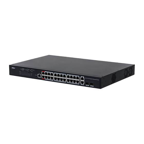
2 Port Description Refer to the following network topology to connect the switch to other network devices. Figure 2-1 Network topology Table 2-1 Description of Indicators and buttons Indicator Description ● Solid on: The total output power of the switch reaches the maximum value. - Page 11 Indicator Description Indicator of Link/Act and PoE. It indicates the connection status or PoE power supply status of RJ45 ports based on the status of the LED Mode button. When the Link/Act indicator is solid on, the descriptions of the Link/Act or PoE indicators are shown as follows: ●...
-
Page 12: Appendix 1 Faq
Appendix 1 FAQ 1. I cannot log in to the webpage of the switch. Try the following solutions: ● Check whether the switch is powered on properly. ● Check whether the computer is connected to the switch properly. ● Check whether the IP address of the computer is set to 192.168.1.X (X ranges from 2 to 254 and is not be occupied). - Page 13 Appendix Figure 1-1 PuTTY configuration c. Double press Enter on your keyboard, and then enter the username and password (both are admin by default) of the switch in the appeared window. Appendix Figure 1-2 Enter username and password 4. How to deal with power system malfunctions? You can determine whether the power system malfunctions by observing the power indicator on the front panel of the switch.
-
Page 14: Appendix 2 Specifications
Appendix 2 Specifications Name Description Number of 10/100/1000 Mbps RJ45 port Port Number of 1000 Mbps 4 independent SFP ports SFP port Console port 1 Baud rate: 115200 Exchange mode Store-and-forward MAC address table Performance Auto aging, auto learning learning MAC address table 16 K PoE standard... -
Page 15: Appendix 3 Cybersecurity Recommendations
IP video surveillance is not immune to cyber risks, but taking basic steps toward protecting and strengthening networks and networked appliances will make them less susceptible to attacks. Below are some tips and recommendations from Dahua on how to create a more secured security system. - Page 16 6. Enable HTTPS We suggest you to enable HTTPS, so that you visit Web service through a secure communication channel. 7. MAC Address Binding We recommend you to bind the IP and MAC address of the gateway to the device, thus reducing the risk of ARP spoofing.
Need help?
Do you have a question about the D-PFS4226-24GT-230 and is the answer not in the manual?
Questions and answers