Table of Contents
Advertisement
Advertisement
Table of Contents

Subscribe to Our Youtube Channel
Related Manuals for Dahua DH-PFS3110-8ET-96


Summary of Contents for Dahua DH-PFS3110-8ET-96
- Page 1 Ethernet Switch (4/8-port Unmanaged Hardened Switch) Quick Start Guide V1.0.2...
-
Page 2: Foreword
Foreword General This manual mainly introduces the hardware, installation, and wiring steps of the 4/8-port unmanaged hardened switch (hereinafter referred to as "the device"). Safety Instructions The following categorized signal words with defined meaning might appear in the manual. Signal Words Meaning Indicates a high potential hazard which, if not avoided, will result in death or serious injury. - Page 3 ● The manual will be updated according to the latest laws and regulations of related jurisdictions. For detailed information, see the paper user’s manual, use our CD-ROM, scan the QR code or visit our official website. The manual is for reference only. Slight differences might be found between the electronic version and the paper version.
-
Page 4: Important Safeguards And Warnings
Important Safeguards and Warnings The manual helps you to use our product properly. To avoid danger and property damage, read the manual carefully before using the product, and we highly recommend you to keep the manual well for future reference. Operating Requirements ●... - Page 5 Maintenance Requirements ● Power off the device before maintenance. ● Mark key components on the maintenance circuit diagram with warning signs.
-
Page 6: Table Of Contents
Table of Contents Foreword ........................................I Important Safeguards and Warnings ............................III 1 Overview ........................................1 1.1 Introduction ....................................1 1.2 Features ......................................1 2 Port and Indicator ....................................2 2.1 Front Panel ....................................2 2.2 Side Panel ...................................... 3 3 Installation ....................................... 5 4 Wiring ......................................... -
Page 7: Overview
1 Overview 1.1 Introduction The device is a hardened switch. It provides a high-performance switching engine and large buffer memory to ensure smooth video stream transmission. With its full-metal and fanless design, the device has great heat dissipation capabilities on its shell surface, and is able to work in environments that range from–30 °C (-22 °F) to +65 °C (+149 °F). -
Page 8: Port And Indicator
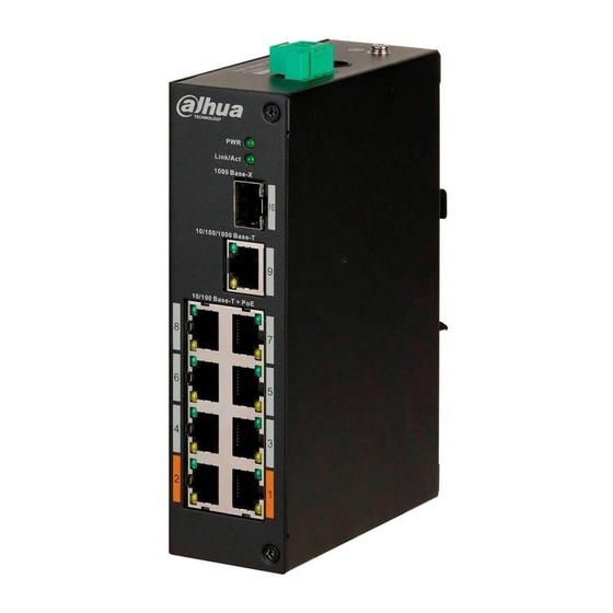
2 Port and Indicator 2.1 Front Panel The following figures are for reference only, and might differ from the actual product. Figure 2-1 Front panel (with PoE) Figure 2-2 Front panel (without PoE) Following are all the ports and indicators on the front panel of the 4/8-port unmanaged hardened switch. -
Page 9: Side Panel
Description 10 Mbps/100 Mbps/1000 Mbps self-adaptive uplink Ethernet port. 1000 Mbps self-adaptive uplink optical port. Optical port connection or data transmission status indicator (Link/Act). ● On: Connected to device. ● Off: Not connected to device. ● Flashes: Transmitting data (1000 Mbps). Power indicator. - Page 10 Figure 2-3 Side panel (with PoE) Table 2-2 Port description (with PoE) Description PD Alive: When a terminal device crash is detected, the device will power down and restart the terminal device. Extend Mode: Extends the maximum transmission distance to 250 m, but reduces average transmission speed to 10 Mbps.
-
Page 11: Installation
3 Installation The device supports DIN-rail mount. Hang the switch hook on the rail, and press the switch to make the buckle latch on to the rail. The width of the guide rail supported by the device is 50 mm. Figure 3-1 DIN rail Name Hook. -
Page 12: Wiring
4 Wiring 4.1 Connecting GND Device GND connection helps ensure device lightning protection and anti-interference. You should connect the GND cable before powering on the device, and power off the device before disconnecting the GND cable. There is a GND screw on the device cover board for the GND cable. It is called enclosure GND. -
Page 13: Connecting Sfp Ethernet Port
Table 4-1 Power terminal description Name DIN rail port (–). DIN rail port (+). Power adapter port. Step 1 Connect the device to the ground. Step 2 Take off the power terminal plug from the device. Step 3 Insert one end of the power cable into the power terminal plug according to requirements. The sectional area of the power cable must be more than 0.75 mm (maximum sectional area is 2.5 mm... -
Page 14: Connecting Ethernet Port
Figure 4-2 SFP module structure Name Gold finger. Optical port. Spring strip. Handle. Figure 4-3 SFP module installation 4.4 Connecting Ethernet Port Ethernet port is a standard RJ-45 port. With its self-adaptation function, it can be automatically configured to full duplex/half-duplex operation mode. It supports MDI/MDI-X self-recognition of the cable, therefore, you can use a cross-over cable or straight-through cable to connect the terminal device to network device. -
Page 15: Connecting Poe Ethernet Port
Figure 4-5 Cable connection 4.5 Connecting PoE Ethernet Port If the terminal device has a PoE Ethernet port, you can directly connect the terminal device PoE Ethernet port to the switch PoE Ethernet port through the network cable to achieve synchronized network connection and power supply. -
Page 16: Appendix 1 Cybersecurity Recommendations
Appendix 1 Cybersecurity Recommendations Mandatory actions to be taken for basic device network security: Use Strong Passwords Please refer to the following suggestions to set passwords: The length should not be less than 8 characters. Include at least two types of characters; character types include upper and lower case ... - Page 17 MAC Address Binding We recommend you to bind the IP and MAC address of the gateway to the device, thus reducing the risk of ARP spoofing. Assign Accounts and Privileges Reasonably According to business and management requirements, reasonably add users and assign a minimum set of permissions to them.
Need help?
Do you have a question about the DH-PFS3110-8ET-96 and is the answer not in the manual?
Questions and answers