Table of Contents
Advertisement
Quick Links
Advertisement
Table of Contents

Subscribe to Our Youtube Channel
Related Manuals for Dahua DH-PFS4226-24GT2GF-360


Summary of Contents for Dahua DH-PFS4226-24GT2GF-360
- Page 1 16/24-Port Gigabit Managed PoE Switch Quick Start Guide V1.0.1...
-
Page 2: Foreword
Foreword General This manual introduces the functions and operations of 16/24-port Gigabit managed PoE switch (hereinafter referred to as "the Device"). Safety Instructions The following categorized signal words with defined meaning might appear in the manual. Signal Words Meaning Indicates a high potential hazard which, if not avoided, will result in death or serious injury. - Page 3 occurring when using the device. ● If there is any uncertainty or controversy, we reserve the right of final explanation.
-
Page 4: Important Safeguards And Warnings
Important Safeguards and Warnings The manual helps you to use our product properly. To avoid danger and property damage, read the manual carefully before using the product, and we highly recommend you to keep it well for future reference. Operating Requirements ●... - Page 5 environment, crush, puncture, cut or incinerate. ● Dispose of the battery as required by local ordinances or regulations.
-
Page 6: Table Of Contents
Table of Contents Foreword ..............................I Important Safeguards and Warnings ....................III 1 Overview ..............................1 1.1 Product Introduction ........................1 1.2 Product Features ........................... 1 1.3 Typical Application ........................1 2 Device Structure ............................ 3 2.1 Front Panel ............................. 3 2.2 Rear Panel ............................ -
Page 7: Overview
1 Overview 1.1 Product Introduction The 16/24-Port Gigabit Managed PoE Switch is designed and developed for field transmission application of high definition video. The product is equipped with high performance switching engine and large buffer, which features low transmission delay and high reliability. With solid and sealed all-metal case design, the product has low power consumption. - Page 8 Figure 1-1 Networking...
-
Page 9: Device Structure
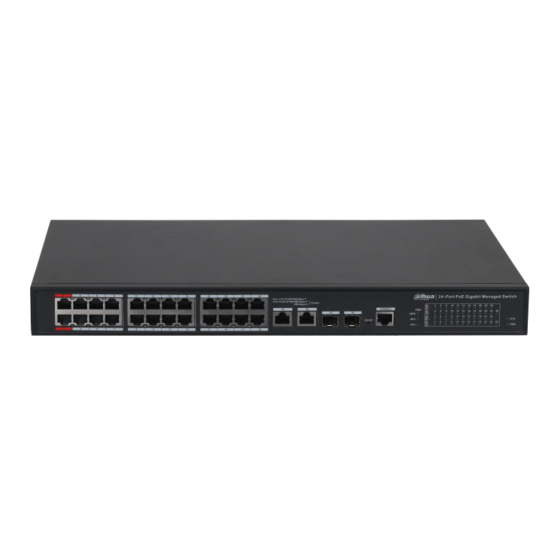
2 Device Structure 2.1 Front Panel 16-Port Gigabit Managed PoE Switch Figure 2-1 Front panel Table 2-1 Front panel description Name Description Ethernet port, supports 10/100/1000 M RJ45 port self-adaptive. 2 Ethernet ports, support 10/100/1000 M COMBO port self-adaptive; 2 optical ports, support 1000 M self-adaptive. -
Page 10: Rear Panel
Name Description 2 Ethernet ports, support 10/100/1000 M COMBO port self-adaptive; 2 optical ports, support 1000 M self-adaptive. Long press the button for 5 s to reset the Reset button Device and recover default configuration. Console serial port Device debugging port. PoE power usage indicator Current power consumption display. -
Page 11: Installation
3 Installation 3.1 Installing the Device The device supports standard rack mount. Install the rack mount kit on both sides of the switch. See Figure 3-1. Figure 3-1 Rack mount 3.2 Wiring 3.2.1 Ethernet Port Figure 3-2 Ethernet port pin number 10/100/1000 M Base-T Ethernet port adopts standard RJ45 port. -
Page 12: Console Port
3.2.2 Console Port Figure 3-4 Console port See Figure 3-4 for console port. The switch console port and computer controlling 9-pin serial port are connected with RJ-45-DB9 cable. You can call the console software of the device by operating the superterminal software of the Windows system for device configuration, maintenance, and management. -
Page 13: Sfp Port
3.2.3 SFP Port The signal is transmitted through laser by optical fiber cable. The laser conforms to the requirement of level 1 laser products. To avoid injury of eyes, do not look at the 1000 Base-X optical port directly when the device is powered on. Figure 3-6 SFP module structure Figure 3-7 SFP module installation Installing SFP Port... -
Page 14: Quick Operations
4 Quick Operations We will introduce VLAN configuration briefly in this section. See the corresponding command line manual for detailed configuration. 4.1 First Login by Console Port It is the most basic way to log in to the local interface via Console port, and it is also the method to configure other ways to log in to the device. - Page 15 Step 6 Enter username and password, and then press Enter. The default username is admin, and the default password is admin. The following command line prompt (SWITCH#) is displayed after pressing Enter, which means login has been successful. Enter corresponding command, and you can configure the device or check device operating status, and you can enter ? anytime if you need help.
-
Page 16: Device Factory Default Configuration
W icfg 18:00:22 71/icfg_commit_tftp_load_and_trigger#2695: Warning: TFTP get bringup-config: Operation timed out. Press ENTER to get started Username: admin Password: SWITCH# Enter corresponding command to configure the device or check device operating status, and you can enter ? anytime if you need help. 4.2 Device Factory Default Configuration You can log in to Web interface of the device via the following IP address. - Page 17 ID when creating VLAN, ranging from 2 to 4094. The switch creates VLAN1 by default and VLAN1 cannot be deleted. Application Example Networking Requirement There are two users, user 1 and user 2. These two users need to be in different VLAN due to different network function and environment.
-
Page 18: Appendix 1 Cybersecurity Recommendations
Appendix 1 Cybersecurity Recommendations Cybersecurity is more than just a buzzword: it’s something that pertains to every device that is connected to the internet. IP video surveillance is not immune to cyber risks, but taking basic steps toward protecting and strengthening networks and networked appliances will make them less susceptible to attacks. - Page 19 6. Enable HTTPS We suggest you to enable HTTPS, so that you visit Web service through a secure communication channel. 7. MAC Address Binding We recommend you to bind the IP and MAC address of the gateway to the device, thus reducing the risk of ARP spoofing.
Need help?
Do you have a question about the DH-PFS4226-24GT2GF-360 and is the answer not in the manual?
Questions and answers