Table of Contents
Advertisement
Quick Links
Advertisement
Table of Contents

Related Manuals for DIEBOLD NIXDORF D1064


Summary of Contents for DIEBOLD NIXDORF D1064
- Page 1 D1064 Customer Display Operator Manual 01750364416 B Customer/Partner Use This document is property of Diebold Nixdorf and is intended for customer/partner use. A written license agreement with Diebold Nixdorf is not required to use this material.
- Page 2 This document and the information contained herein are provided AS IS AND WITHOUT WARRANTY. In no event shall Diebold Nixdorf or its suppliers be liable for any special, indirect, or consequential dam- ages of any nature resulting from the use of information in this manual. The information contained in this document is subject to change without notice.
-
Page 3: Table Of Contents
5 Supplier’s Declaration of Conformity ..................5-1 6 Overview ............................. 6-1 D1064 on a stand.......................6-1 D1064 on a pole.........................6-2 D1064 on a A-Series AIO or Display..................6-3 7 Initial Setup..........................7-1 Unpacking and Checking the Delivery Unit................7-1 Mounting Options and Connection Cables.................7-1 Installing the D1064 Display....................7-4... - Page 4 ESC / POS Commands ......................9-11 9.2.1 Supported Commands ..................9-11 9.2.2 Unsupported Commands ..................9-12 9.2.3 USB Commands ....................9-13 9.2.4 Status Bytes Definitions ..................9-18 9.2.5 Middleware......................9-19 10 Technical Data..........................10-1 10.1 Dimensions (mm) .......................10-2 Copyright © 2022, Diebold Nixdorf 01750364416 B...
- Page 5 Figure 6-1 D1064 mounted on a Stand ...................6-1 Figure 6-2 D1064 mounted on a pole ..................6-2 Figure 6-3 D1064 on a A-Series AIO or Display..............6-3 Figure 7-1 Threading the cable through the stand ..............7-5 Figure 7-2 Connect the RJ45 cable ..................7-5 Figure 7-3 Secure the RJ45 cable ...................7-6...
-
Page 6: Document History
1 Document History Part Number Date Remarks 01750364416 A 02/2022 Creation of the manual 01750364416 B 04/2022 Addition of part numbers and smaller improvements Copyright © 2022, Diebold Nixdorf 01750364416 B... -
Page 7: About This Manual
The detailed table of contents helps you find the desired information quickly and easily. NOTE Note This is how notes are displayed in this manual. WARNING Warning This is how warnings are displayed in this manual. Copyright © 2022, Diebold Nixdorf 01750364416 B... -
Page 8: Introduction
3 Introduction The D1064 is a rejuvenate successor of the BA64-2 Customer Display for the A-Series Family of POS system. The radiant and high contrast nature of the VFD technology makes it an excellent choice for a customer display. The D1064 operates in either USB or RS232 mode depending on the cable option you select. -
Page 9: Manufacturer's Declaration And Approval
This device complies with part 15 of the FCC Rules. Operation is subject to the following two conditions: (1) This device may not cause harmful interference, and (2) this device must accept any interference, in- cluding interference that may cause undesired operation. CAN ICES-3 (A)/NMB-3 (A) Copyright © 2022, Diebold Nixdorf 01750364416 B... - Page 10 DIN VDE 0100, part 540, Appendix C2, as well as EN50174-2, §5.4.3. Warranty Diebold Nixdorf guarantees generally a warranty engagement for 12 months beginning with the date of delivery. This warranty engagement covers all those damages which occur despite a normal use of the product.
- Page 11 There are still some parts that are not reusable. Diebold Nixdorf guarantees the environmentally safe disposal of these parts in a Recycling Center, which is certified pursuant to ISO 9001 and ISO 14001.
-
Page 12: Supplier's Declaration Of Conformity
5 Supplier’s Declaration of Conformity Product Description: Customer Display Model: D1064 Party issuing Supplier’s Declaration of Conformity Diebold Nixdorf Singapore PTE. LTD. 30A Kallang Place, #04-01 Singapore 339213 Phone: +65 6747 3828 Responsible Party – U.S. Contact Information Diebold Nixdorf... -
Page 13: Overview
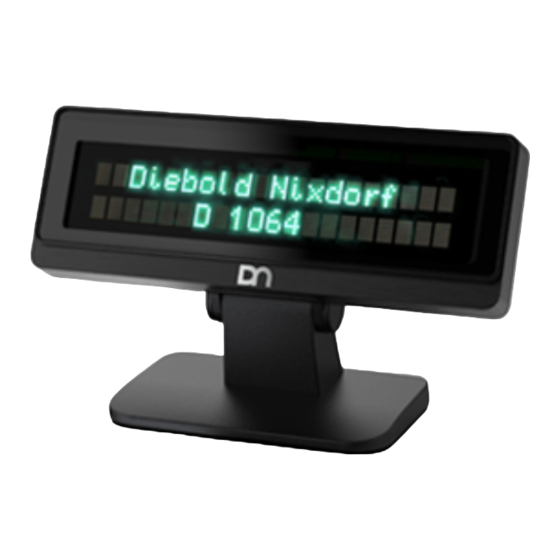
6 Overview Below you will find reference pictures showing the D1064 in various installation situations. The installa- tion components, such as the pole itself, are not part of the scope of delivery of the D1064. NOTE The pictures may differ in detail from the product you received. -
Page 14: D1064 On A Pole
Overview D1064 on a pole Figure 6-2: D1064 mounted on a pole Copyright © 2022, Diebold Nixdorf 01750364416 B... -
Page 15: D1064 On A A-Series Aio Or Display
Overview D1064 on a A-Series AIO or Display Figure 6-3: D1064 on a A-Series AIO or Display Copyright © 2022, Diebold Nixdorf 01750364416 B... -
Page 16: Initial Setup
Mounting adapters can be ordered separately depending on the intended installation situation. Data ca- bles required for operation can be ordered separately. If damage has occurred during transport or the contents of the package do not match the delivery note, inform your Diebold Nixdorf sales office immedi- ately. - Page 17 Pole Adapter consists of: Illustration Part Number Item 01750279878 1x Pole mount assembly A-Series dual display adapter consists of: Illustration Part Number Item 01750342563 1x Display adapter 2x Torx countersunk screws M4x8 (Part number: 01750335349) Copyright © 2022, Diebold Nixdorf 01750364416 B...
- Page 18 USB to RJ45 cable, 5.0m, black 01750349276 RJ45 to USB cable (0,42.) 01750243975 RS232 to RJ45 cable, 1.5m, black 01750243977 RS232 to RJ45 cable, 3.0m, black 01750243979 RS232 to RJ45 cable, 5.0m, black Copyright © 2022, Diebold Nixdorf 01750364416 B...
-
Page 19: Installing The D1064 Display
Initial Setup Installing the D1064 Display 7.3.1 7.3.1 Installing System to the Stand To install the D1064 Display to a pole you will need the following parts: Illustration Item 1x Unit of D1064 Display 1x Unit of Stand 1x Unit of connection cable Copyright ©... - Page 20 Initial Setup 1. Thread the RJ45-end of the connection cable through the stand. Figure 7-1: Threading the cable through the stand 2. Connect the RJ45 connector (1) to the D1064 Figure 7-2: Connect the RJ45 cable Copyright © 2022, Diebold Nixdorf 01750364416 B...
- Page 21 3. Secure the cable in the strain relief (1) at the back of the D1064. Figure 7-3: Secure the RJ45 cable 4. Secure the D1064 with two ‚Torx screw M4x6‘ (1) to the stand. Figure 7-4: Secure the Display to the stand Copyright ©...
- Page 22 Initial Setup 5. Secure the cable in the strain relief (1) at the base of the stand. Figure 7-5: Secure cable in the stand • Display D1064 mounted on a stand. Figure 7-6: Finished installation Copyright © 2022, Diebold Nixdorf 01750364416 B...
-
Page 23: Installing System To The Pole
Initial Setup 7.3.2 7.3.2 Installing System to the Pole To install the D1064 Display to a pole you will need the following parts: Illustration Item 1x Unit of D1064 Display 1x Unit of Pole mount adapter 1x Unit of connection cable Copyright ©... - Page 24 2. Slide the pole mount adapter onto the pole. Figure 7-7: Mount adapter to pole 3. Connect the RJ45 connector (1) the the D1064. Figure 7-8: Connect the cable Copyright © 2022, Diebold Nixdorf 01750364416 B...
- Page 25 4. Secure the cable in the strain relief (1) at the back of the D1064. Figure 7-9: Attach cable to strain relief 5. Secure the D1064 with two ‚Torx Screws M4x6’ (1) to the adapter. Figure 7-10: Mount the Display to the adapter Copyright ©...
- Page 26 Initial Setup 6. Locate the screw hole on the pole. 7. Use a M3 screw to secure the D1064 and pole mount adapter assembly to the pole. Figure 7-11: Secure adapter on the pole • Display D1064 mounted on a pole.
-
Page 27: Installing System To A A-Series Aio Or Display
Initial Setup 7.3.3 7.3.3 Installing System to a A-Series AIO or Display To install the D1064 Display to a A-Series AIO or Display you will need the following parts: Illustration Item 1x Unit of D1064 1x Unit of A-Series dual disaply adapter for D1064 1x Unit of connection cable (0,5m) Copyright ©... - Page 28 Initial Setup 1. Pull the VESA cover downwards from the stand (1). Figure 7-13: Remove the VESA cover 2. Remove the breakaway (1) from the VESA cover. Figure 7-14: Remove the breakaway Copyright © 2022, Diebold Nixdorf 7-13 01750364416 B...
- Page 29 3. Remove the cable cover (1) from the Beetle A-series system. Figure 7-15: Removing the cable cover 4. Loosen the M3x8 screws (2) slighty. 5. Remove the mounting adapter (1). Figure 7-16: Loosen adapter screws Copyright © 2022, Diebold Nixdorf 7-14 01750364416 B...
- Page 30 7. Thread the RJ45 connector through the adapter (1). Figure 7-17: Threading the RJ45 cable 8. Remove the M4x6 torx screws (1) from the D1064. Figure 7-18: Removing screws from the D1064 Copyright © 2022, Diebold Nixdorf 7-15 01750364416 B...
- Page 31 10. Secure the cable in the strain relief (2) at the back of the display. Figure 7-19: Connecting the RJ45 plug 11. Insert the mounting adapter (2) and secure it with the previously removed screws (1). Figure 7-20: Mounting the adapter to D1064 Copyright © 2022, Diebold Nixdorf 7-16 01750364416 B...
- Page 32 Figure 7-21: Removing top screws 13. Insert the mounting adapter (1) as directed by the arrow. 14. Secure the mounting adapter with the previ- ously removed screws (2). Figure 7-22: Mounting the adapter to the stand Copyright © 2022, Diebold Nixdorf 7-17 01750364416 B...
- Page 33 Initial Setup 15. Slot in the D1064 assembly (1) to the mount- ing adapter. 16. Tighten the previously loosened M3x8 torx screws (2). Figure 7-23: Mount the Display to the adapter 17. Thread the USB cable trough the gap be- tween the Beetle and the marked beam.
- Page 34 18. Connect the USB cable to an available USB port (1). Figure 7-25: Connect the cable 19. Attach the cable cover (1) to the Beetle A-se- ries system. Figure 7-26: Mounting the cable cover Copyright © 2022, Diebold Nixdorf 7-19 01750364416 B...
- Page 35 22. Bend the cable at (2) and (3). 23. Lay the cable into the cable channel (4). NOTE Cabble routing Make sure the cable stays in position when attaching the VESA cover to the stand. Copyright © 2022, Diebold Nixdorf 7-20 01750364416 B...
- Page 36 Initial Setup 24. Push the VESA cover upwards to mount it to the stand (1). Figure 7-28: Mount the VESA cover • Display D1064 mounted on a A-Series AIO or Display Figure 7-29: Finished installation Copyright © 2022, Diebold Nixdorf 7-21 01750364416 B...
-
Page 37: Display Characteristics
8 Display Characteristics Screen Coordinates The D1064 is a text display of 2 rows by 20 characters. Each character has a resolution of 5 pixels width and 7 pixels height. The origin of the coordinate system is at the top-left corner of the screen as shown above. -
Page 38: Display Commands
9 Display Commands Control Characters and ESC Sequences The table below is a summary of the control characters and escape sequences supported by the D1064. Command Description Backspace Line Feed Carriage Return ESC [ 0 K Delete to End of Line... -
Page 39: Backspace
ESC [ 0 K 1B 5B 30 4B Description: This command deletes the characters from the cursor, including the cursor position to the end of the row. The position of the cursor remains unchanged. Copyright © 2022, Diebold Nixdorf 01750364416 B... -
Page 40: Clear Screen
';' in between are dropped, the cursor is positioned at the home position, i.e. coordinate (1,1). Notes: Default position of cursor is (1,1). Valid ranges of value are 1 to 2 for <y> and 1 to 20 for <x>. Copyright © 2022, Diebold Nixdorf 01750364416 B... -
Page 41: Set Country Code
This command set the specific character set for the respective country code defined by parameter <n> as shown above. Notes: The default is the USA character set (n = 00). This command is not supported in UTF-8 and UTF-16 mode. Copyright © 2022, Diebold Nixdorf 01750364416 B... -
Page 42: Display Identification
If country code is not defined for the current codepage <p3> shall be empty. <p4> Number of rows <p5> Column / Line Notes: This command is not supported in USB mode. Copyright © 2022, Diebold Nixdorf 01750364416 B... -
Page 43: Character Set Identification
– p1 and p2 are the boot firmware version and subversion number – p3 and p4 are the main firmware version and subversion number. Notes: This command is not supported in USB mode. Copyright © 2022, Diebold Nixdorf 01750364416 B... -
Page 44: Set Compatibility Mode
ESC [ <n> E 1B 5B <n> 45 n is a ASCII coded decimal number: Display Mode BA64 Native Mode ESC/POS Mode BA63 Emulation Mode Notes: This command is not supported in USB mode. Copyright © 2022, Diebold Nixdorf 01750364416 B... -
Page 45: Set Baud Rate For Serial Port
38400 bps 56000 bps 57600 bps 115200 bps Note: This command is applicable only to the RS232C interface. This command is not applicable in Unicode mode, use the alternate command instead, see Section 9.1.14. Copyright © 2022, Diebold Nixdorf 01750364416 B... -
Page 46: Set Serial Port
1B 5B <n> 75 n is a ASCII coded decimal number defined as follow: Display Mode Set ASCII Encode/Decode mode Set UTF-8 Encode/Decode mode Set UTF-16 Encode/Decode mode Description: An encode/decode mode change resets the display. Copyright © 2022, Diebold Nixdorf 01750364416 B... -
Page 47: Read Character Encode/Decode Mode
9.1.18 9.1.18 Restore Configuration Data to Factory Default Code Hexadecimal ESC + 0 w 1B 2B 30 77 Description: This command restores all settings to the factory default configuration. Copyright © 2022, Diebold Nixdorf 9-10 01750364416 B... -
Page 48: Esc / Pos Commands
Display Commands ESC / POS Commands The D1064 supports a reduced EPSON command set of ESC/POS commands. Please refer to EPSON Application Programming Guide for a detailed description of the commands. 9.2.1 9.2.1 Supported Commands The table below lists the supported commands. -
Page 49: Unsupported Commands
Display Commands 9.2.2 9.2.2 Unsupported Commands The following table lists the commands which are not supported by D1064. These unsupported com- mands are parsed and discarded. Command Description Hexadecimal ESC = Select peripheral device 1B 3D <n> ESC % Select/Cancel user-defined character set 1B 25 <n>... -
Page 50: Usb Commands
Display Commands 9.2.3 9.2.3 USB Commands This chapter describes the USB command format and the commands that the D1064 supports. 9.2.3.1 9.2.3.1 Command Format Command: Byte # Name Number of Description bytes Command byte 1 First command byte Command byte 2... - Page 51 Code page loaded in space page Serialnumber Pn1 to Pn7 are string encoded in the current encoding mode, either in ASCII, UTF-8 or UTF-16. Description: This command is used to get display identification from the device. Copyright © 2022, Diebold Nixdorf 9-14 01750364416 B...
- Page 52 1-Byte value representing bytes count of the following data (w/o ‘count’ byte) BL-Version Bootloader version – 2-byte value, BCD coded Main version Main Firmware version – 2-byte value, BCD coded Description: This command returns the bootloader version and main firmware version. Copyright © 2022, Diebold Nixdorf 9-15 01750364416 B...
- Page 53 00h, 10h Response 04h, <status byte 1>, <status byte 2>, <status byte 3> Description: This command starts a self-test of the display. The response will be sent at the end of the test. Copyright © 2022, Diebold Nixdorf 9-16 01750364416 B...
- Page 54 Display Commands 9.2.3.11 9.2.3.11 Restore Factory Default Command FBh, 00h Response 04h, <status byte 1>, <status byte 2>, <status byte 3> Description: This command resets the settings to the default factory settings. Copyright © 2022, Diebold Nixdorf 9-17 01750364416 B...
-
Page 55: Status Bytes Definitions
3 status bytes followed by the data. The Host software will have to combine the data from each segment to form a complete data transfer. Copyright © 2022, Diebold Nixdorf 9-18... -
Page 56: Middleware
If the user prefers COM interface for ease of programming but the host system lacks a powered COM port, use the VirtualCOM driver to virtualize the D1064 with as USB interface as a COM device. Copyright © 2022, Diebold Nixdorf... -
Page 57: Technical Data
Supported OS Windows 10, Linux Operating Enviroment 0°C to 40°C 5% to 85% RH Certifications CE Class B and FCC Class A Dimensions (WxHxD) 199.9 x 71.1 x 27.1 mm Weight 235 g Copyright © 2022, Diebold Nixdorf 10-1 01750364416 B... -
Page 58: Dimensions (Mm)
Technical Data 10.1 10.1 Dimensions (mm) D1064 Dimensions Copyright © 2022, Diebold Nixdorf 10-2 01750364416 B... - Page 59 Technical Data D1064 Stand Dimensions Copyright © 2022, Diebold Nixdorf 10-3 01750364416 B...
- Page 60 Technical Data Pole Adapter Dimensions Copyright © 2022, Diebold Nixdorf 10-4 01750364416 B...
- Page 61 Technical Data D1064 A-Series AIO Adapter Copyright © 2022, Diebold Nixdorf 10-5 01750364416 B...
- Page 62 Vacuum Fluorescent Display Clear To send DBCS Double-Byte Character Set Federal Communications Commission International Organization for Standardization OPOS OLE (Object Linking and Embedding) for Retail Operating System Point Of Sales Relative Humidity Request To Send Copyright © 2022, Diebold Nixdorf 01750364416 B...
- Page 63 DIEBOLD NIXDORF, Incorporated 50 Executive Pkwy | PO Box 2520 | Hudson, OH 44236 | USA © 2022 Diebold Nixdorf, Incorporated. All Rights Reserved.
Need help?
Do you have a question about the D1064 and is the answer not in the manual?
Questions and answers