
Related Manuals for Parker ECL E Series


Summary of Contents for Parker ECL E Series
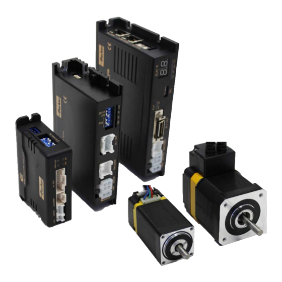
- Page 1 PARKER ECL E Series Closed Loop Stepper Systems Effective: October 2016 © 2016 Parker Hannifin Corporation All Rights Reserved...
-
Page 2: Table Of Contents
Contents Introduction Before Operation ............................... 6 Safety Precautions ............................. 7 Product Specification 1.1 Part Numbering ..........................11 1.2 Product Dimension ..........................13 1.3 EtherCAT Specifications ........................14 1.4 Drive Specification ..........................15 Installation 2.1 Precautions of Installation ........................ 17 2.2 System Configuration ........................ -
Page 3: Contents
Contents 4.4.2 Related Objects .......................... 39 4.4.3 Control word and Status word ....................39 4.5 Profile Position Mode........................41 4.5.1 Definition ............................ 41 4.5.2 Related Objects .......................... 41 4.5.3 Control word and Status word ....................41 4.5.4 Position movement method ...................... - Page 4 6.2.6 Object 1010h: Store parameters ....................67 6.2.7 Object 1011h: Restore default parameters ................67 6.2.8 Object 1018h: Identity....................... 68 6.2.9 Object 10F1h: Error settings ..................... 68 6.3 PDO Mapping Object......................... 69 6.3.1 Object 1600h: RxPDO-Map 0 ....................69 6.3.2 Object 1601h: RxPDO-Map 1 ....................
- Page 5 Contents 6.5.43 Object 6502h: Supported drive modes ..................86 6.6 Manufacture specific Object ......................87 6.6.1 Object 2001h: Sensors logics ....................87 6.6.2 Object 2002h: Reverse limit direction ..................87 6.6.3 Object 2003h: Limit stop method ..................... 88 6.6.4 Object 2005h: Encoder resolution ....................
-
Page 6: Introduction
Introduction Before Operation... - Page 7 Since Parker Hannifin constantly strives to improve all of its products, we reserve the right to modify equipment and user guides without prior notice. No part of this user guide may be reproduced in any form without the prior consent of Parker...
-
Page 8: Product Specification
Chapter 1 Product Specification... -
Page 9: 1.1 Part Numbering
1.1 Part Numbering... -
Page 11: 1.2 Product Dimension
1.2 Product Dimension Figure 1.3: Dimensions... -
Page 12: 1.3 Ethercat Specifications
1.3 EtherCAT Specifications Type of Communiation EtherCAT Physical Layer Ethernet - 100BASE-TX RJ45 (shielded) Connector ECAT IN : EtherCAT Input ∼ ECAT OUT : EtherCAT Output ∼ Set Configured Station Alias by ECAT ID Switch : 1 ECAT Device ID Set Physical Address at Master : 1 65535 Line... -
Page 13: 1.4 Drive Specification
1.4 Drive Specification Input Voltage 24VDC ±10% Control Method 32bit ARM based Closed-loop Control ∼ Current Consumption 500 mA (Except Motor Current) ∼ In Use : 0 55℃ Ambient ∼ Temperature In Storage : -27 70℃ ∼ Operating In Use : 35 85%RH Humidity Condition... -
Page 14: Installation
Installation Chapter 2... -
Page 15: Precautions Of Installation
Precautions of Installation 1. This product designed for indoor usage and the ambient temperature of the room should be 0 55℃. ∼ 2. If temperature of the case is 50℃, radiate the outside to cool down. 3. Do not install this product under direct rays or near magnetic or radioactive objects. 4. -
Page 16: System Configuration
System Configuration ⑤EtherCAT Cable Figure 2.1: System Configuration Diagram... -
Page 17: External Wiring Diagram
External Wiring Diagram... -
Page 19: Appearance And Part Name
Appearance and Part Name EtherCAT ID Display EtherCAT INPUT Drive Status LED Connector EtherCAT OUTPUT EtherCAT Status LED Connector EtherCAT ID Setting I/O Connector Encoder Connector Motor Connector Power Connector Figure 2.4: External Appearance 2.4.1 EtherCAT ID EtherCAT ID Indication EtherCAT ID Setting Figure 2.5: EtherCAT ID ID Setting... - Page 20 Address assigned due to no connection between controller and master, It indicates 0. Once Master assigns each controllers physical address, it indicates relevant value. • If Rotary switch set as not 0 but other value, 7-Segment indicates relevant set value (EtherCAT configured Alias).
-
Page 21: Ethercat Status Indication Led
• If 7-Segment of ID blinks, It indicates ID value as not applied yet. It can be applied once power turn on again. Error value indication If error generates from controller (Fault Status), 7-Segment indicates Error value instead of EtherCAT ID Value. Error value is ‘E-000’... -
Page 22: Ethercat Communication Connection
Figure 2.8: EtherCAT LED 2.4.3 EtherCAT Communication Connection Connect communication cable from Master into communication connection ECAT IN. If there is next controller, connect communication cable from ECAT OUT to next controller of ECAT IN. EtherCAT Communication Cable Recommend to use communication cable Min. CAT5e level above. •... -
Page 23: I/O Connector
2.4.4 I/O Connector Function LIMIT+ Input LIMIT- Input ORIGIN Input User Input 1 Input User Input 2 Input User Input 3 Input User Input 4 Input User Input 5 Input User Input 6 Input User Input 7 Input User Output 1 Output User Output 2 Output... - Page 24 • Less than 30V of supply voltage • Less than 15mA of current flow...
-
Page 25: Encoder Connection Connector
2.4.5 Encoder Connection Connector Function 5VDC 5VDC GND Frame GND Frame GND Table 2.3: Encoder Connection Connector Encoder Connector (Type of Connector: Molex 55959-1030) 2.4.6 Motor Connection Connector Function A Phase B Phase /A Phase /B Phase Table 2.4: Motor Connection Connector Motor Connector (Type of Connector: Molex 5569-04A2) 2.4.7 Power Connection Connector... -
Page 26: Ethercat Communication
Chapter 3 EtherCAT Communication... -
Page 29: Can Application Protocol Over Ethercat
3. EtherCAT Communication CAN application protocol over EtherCAT ECL EtherCATdrive utilizes EtherCAT communication embedded type of controller to support CAN application protocol over EtherCAT (CoE). EtherCAT Slave structure is as below. Figure 3.1: EtherCAT Structure 3.1.1 Object Dictionary Object Dictionary is dictionary of Objects what product has. 3.1.2 Mailbox Communication Master and Slave commands and receives Service Data Object (SDO) at Mailbox communication (SDO... -
Page 30: Process Data Communication
3.1.3 Process Data Communication Process Data Communication (PDO Communication) commands and receives Process Data Objects (PDO) with Master periodically. Data that will be delivered and received is already defined at the initial stage of communication by PDO Mapping. PDO communication is categorized as transmission PDO (following Tx PDO) delivers controller status information and Receipt PDO (following Rx PDO) delivers command from master. -
Page 31: Pdo Mapping & Module
3. EtherCAT Communication PDO Mapping & Module PDO Mapping is to set Application Object will be delivered and received by PDO communication. 3.2.1 PDO Mapping Tx PDO Mapping information to be delivered to Master is to set at 1600h 1601h Object and Rx PDO ∼... -
Page 32: Module
3.2.3 Module With selection of Module, possible to set pre-assigned PDO Mapping and assign correspondent PDO Mapping at SyncManager. Module provided from controller is as below. Module Set Name Rx PDO Assign Tx PDO Assign 119800h csp - axis : Axis only supports csp 1600h 1A00h 219800h... -
Page 33: Ethercat State Machine
3. EtherCAT Communication EtherCAT State Machine INIT PRE-OP BOOT SAFE-OP Figure 3.5: EtherCAT State Machine EtherCAT controller of status motion is controlled by EtherCAT Master. Status Rx PDO Tx PDO Description EtherCAT communication is to reset. Sta- INIT Non Available Non Available Non Available tus of communication is not available at this... -
Page 34: Synchronization
Synchronization Synchronisation modes provided from controller are as below. possible framejitter (-㎲) due to EtherCAT Master Implementation EtherCAT frame EtherCAT frame (jitter: ~㎲) DC Sync Even DC Sync Event DC Sync Event DC Sync Event (jitter: ~㎱) Free Run Local Timer Event SM Event (No Synchronization) Slave Task... -
Page 35: Ethercat Slave Information
3. EtherCAT Communication EtherCAT Slave Information EtherCAT Slave Information file (XML File) is needed to connect controller with EtherCAT Master. This file is described slave device information as XML format based on EtherCAT specifications. With recording of XML file into EtherCAT Master Equipment through EtherCAT setting equipment, easily implement PDO and SDO setting of Slave device. -
Page 36: Cia 402 Drive Profile
Chapter 4 CiA 402 Drive Profile... -
Page 39: 4.1 Drive Status Control
4. CiA 402 Drive Profile 4.1 Drive Status Control Status of product moves as follows. Status movement is executed by status of controller and Control word (6040h) and current status can be checked by Status word (6041h). Start Not ready to Low level power switch on Supply Controller Power... - Page 40 Each status of functions supported by controller as follows. Status Brake Function Motor Power Control Command Not ready to switch on Switch on disabled Ready to switch on Switched on Operation enabled Quick stop active Fault reaction active Fault Table 4.2: Function per Status Able to control the status of controller by 0 3, 7 bits of Control word and bits per target status are as ∼...
-
Page 41: Error Code
4. CiA 402 Drive Profile Error Code Once Error generates at Controller (Sense Fault signal), changed to ‘Fault reaction active’ status. Under Fault / Fault reaction active status, types of error can be checked by Error code (603Fh). Indicated Error codes are as follows Error code External Status... -
Page 42: 4.3 Mode Of Operation
4.3 Mode of Operation Currently activated Mode of operation display (6061h) decides the action of controller. Meaning for some bits of Control word (6040h) and Status word (6041h) Objects can be decided by Mode of operation display (6061h). Able to set selected operation mode by Mode of operation (6060h). Currently activated operation mode can be checked by Mode of operation display (6061h). -
Page 43: 4.4 Cyclic Synchronous Position Mode
4. CiA 402 Drive Profile 4.4 Cyclic Synchronous Position Mode 4.4.1 Definition Cyclic Synchronous Position mode(CSP Mode) assigns target position to controller by Master’s operation profile creation function throughcyclic communication. Controller internally executes position / velocity control with receipt of target position in each cycle. To use CSP Mode, Mode of operation (6060h) Cyclic Synchronous Position Mode needs to be set. - Page 44 Name Description Ready to switch on Switched on Operation enabled Fault Voltage enabled Quick stop Switch on disabled Warning Reserved Remote reserved Internal Limit Active Whether target position moved Target position ignored ∼ Following Error Following Error Reserved Table 4.8: Status word of CSP Mode Please refer to drive status control for the rest of bits.
-
Page 45: Profile Position Mode
4. CiA 402 Drive Profile Profile Position Mode Definition 4.5.1 Position control mode is to move to target position of Target position (607Ah) object with receipt of Control word (6040h) input. It is general Point to point operation. To use position control mode, need to set Profile Position Mode at Mode of operation (6060h). - Page 46 ∼ Reserved Table 4.12: Profile Position Mode of Control Word Please refer to for the rest of bits.
- Page 47 4. CiA 402 Drive Profile Bit 5 Bit 4 Description 0 → 1 Execute position movement command after completion of previous command. 0 → 1 Execute position movement command with ignorance of previous position. Table 4.13: Control Word of Bit 4, 5 Value Description Target position (607Ah) is absolute position.
-
Page 48: Position Movement Method
Value Description Following Error generated. Table 4.19: Status word of Bit 13 Position movement method 4.5.4 General Movement Movement command to new target position can be requested by changing Control word (6040h) of New Set-Point (Bit 4) from RESET to SET. Once controller receives this request, Set-Point Acknowledge of Status word (Bit 12) is going to be SET and position movement command executed. - Page 49 4. CiA 402 Drive Profile Actual Speed Set-Point (Bit 4) Target Position Current target position processed Set-Point Acknowledge (Bit 12) Target Reached (Bit 10) Figure 4.5: Next Set-Point At this time, Status word of Set-Point Acknowledge (Bit 12) is going to be RESET of Control word of Ne Set-Point (Bit 4) and it goes to RESET after completion of previous position movement command.
- Page 50 Actual Speed Set-Point (Bit 4) Target Position Current target position processed Set-Point Acknowledge (Bit 12) Target Reached (Bit 10) Figure 4.6: Change Set Immediately 1. If new target position is sufficiently ahead of previous target position, it will move to new target position passing by previous target position.
-
Page 51: Homing Mode
4. CiA 402 Drive Profile Homing Mode Definition 4.6.1 Origin search mode is the way of heading to origin with command of Control word (6040h). To use origin search mode, need to set Homing Mode at Mode of operation (6060h). Able to use origin search command once Mode of operation display (6061h) indicates Homing Mode. - Page 52 Please refer to drive status control for the rest of bits.
- Page 53 4. CiA 402 Drive Profile Value Description Initiate origin search command. 0 → Origin search command cancelled and stops according to set action at Halt option code (605Dh). Table 4.21: Control Word of Bit 4, 8 Status word at Homing Mode are as follows. Value Description Ready to switch on...
-
Page 54: Origin Search Method
Origin Search Method 4.6.4 Origin search methods supported by this product are as follows. Homing method Name Homing on Negative Limit Switch and Index Pulse Homing on Positive Limit Switch and Index Pulse Homing on Origin Switch (Positive Direction, Negative Edge) and Index Pulse Homing on Origin Switch (Negative Direction, Positive Edge) and Index Pulse Homing on Negative Limit Switch Homing on Positive Limit Switch... - Page 55 4. CiA 402 Drive Profile Method 2: Homing on Positive Limit Switch and Index Pulse Index Pulse Positive Limit Switch Figure 4.9: Homing Method 2 This origin methods is to start toward Positive Direction and movement velocity is the value of Speed during search for switch (6099h, index 01h).
- Page 56 Method 11: Homing on Origin Switch (Negative Direction, Positive Edge) and Index Pulse Index Pulse Home Switch Negative Limit Switch Figure 4.11: Homing Method 11 Initial movement direction of this origin search method is Negative Direction and movement velocity is the value of Speed during search for switch(6099h, index 01h).
- Page 57 4. CiA 402 Drive Profile Method 18: Homing on Positive Limit Switch Positive Limit Switch Figure 4.13: Homing Method 18 This origin method goes for Positive Direction and movement velocity of the value of Speed during search for switch (6099h, index 01h). Positive Limit Switch goes ON, it goes to opposite direction by velocity of Speed during search for zero (6099h, index 02h) Limit Switch goes OFF then stops and set correspondent position as sensor origin position.
- Page 58 Method 28: Homing on Origin Switch (Negative Direction, Positive Edge) Home Switch Negative Limit Switch Figure 4.15: Homing Method 28 Initial movement direction of this origin search method is Negative Direction and movement velocity is the value of Speed during search for switch (6099h, index 01h). Negative Limit Switch goes ON, it goes to opposite direction.
- Page 59 4. CiA 402 Drive Profile Method 37: Set the current position origin and reset current position This origin search method is to set current position as sensor origin position. If set value of Home offset (607Ch) is not 0, initialize current position as Home offset value.
- Page 60 Method -3: Homing on Negative Limit touch This origin search method is to start toward Negative Direction and movement velocity is the value of Speed during search for zero (6099h, index 02h). If it sense certain Load then stops and set correspondent position as sensor origin position.
-
Page 61: Touch Probe
4. CiA 402 Drive Profile Touch Probe Definition 4.7.1 Touch probe function is to record current position with sensing inputs from external signal. Related Objects 4.7.2 Object Access Description Touch probe function Control Touch Probe 1/2. Touch probe status Indicate status of Touch Probe 1/2. Touch probe 1 positive value Indicate detected position of Rising edge of Touch Probe 1. -
Page 62: Touch Probe Status And Control
Touch Probe Status and Control 4.7.3 Touch Probe Operation : Acknowledge initial signal If Touch probe function of bit number 1, 9 has set as O, Touch probe only uses initially acknowledged signal after Enable. Please refer to Timing chart as follow. 60B8h Bit 0 / Bit 8 60B8h... - Page 63 4. CiA 402 Drive Profile Touch Probe Operation : Continuous signal acknowledgement If Touch probe function of bit number 1, 9 has set as 1, Touch probe uses all acknowledged signals after Enable. Please refer to Timing chart as follows. 60B8h Bit 0 / Bit 8 60B8h...
-
Page 64: Digital Input And Output
Digital Input and Output Definition 4.8.1 ECL EtherCAT drive provides 3 default input (ORIGIN, LIMIT+, LIMIT-) and 7 user inputs and also 1 default output (BRAKE) and 6 user outputs. Related Objects 4.8.2 Object Access Description Digital inputs (60FDh) Indicates input signals. Digital outputs (60FEh) Set output signals. -
Page 65: Origin And Limit Input
4. CiA 402 Drive Profile ORIGIN and LIMIT Input 4.8.4 Active Level of ORIGIN and LIMIT input signal can be changed through Sensors logics (2001h) of Bit 0, 1. Please refer to Sensors logics. LIMIT+ and LIMIT- input signals can be exchanged through Reverse limit direction (2002h). Interrelation between Polarity (607Eh), Reverse limit direction (2002h) and LIMIT+, LIMIT- is as fol- lows. -
Page 66: Operataion
Chapter 5 Operataion... -
Page 68: Operation Sequence
Operation Sequence Sequence of controller operation is as follow. Exampled operation sequence of Profile Position Mode listed at the table as below.. Step Name Action Install motor/controller according to conditions of installa- Installation tion. Wiring Check power cable, motor/encoder cable, I/O cable, Ether- Setting CAT communication cables are properly connected. -
Page 69: Operation
5. Operataion Operation Drive Status Control 5.3.1 Change Drive State Machine as ‘Operation Enabled’ by setting of Control word (6040h). • Check Status word (6041h) whether it can be changing to ‘Operation Enabled’. • In case of changing to ‘Fault’ status, check type of error by Error code (603Fh). Execute appropriate action according to type of error. - Page 70 If rotation direction of motor goes opposite direction, set Polarity (607Eh) value then able to change rotation direction of motor.
-
Page 71: Change I/O Signal Level
5. Operataion Reverse limit direction After changing Polarity, if LIMIT+, LIMIT- input signal acknowledgement reversed, able to change input value of 2 signals by setting the value of Reverse limit direction (2002h). Regarding relationship between Reverse limit direction and Limit Sensors, please refer to 4.8.5 BRAKE Output. -
Page 72: Ethercat Object Dictionary
Chapter 6 EtherCAT Object Dictionary... - Page 74 Indication Type of Objects Following table explains indication type of information for each object. Value Default Index Name Type Access SAVE index Mapping Range Value ∼ 60C2h Number of entries Interpolation time ∼ 65535 period value Interpolation time index Object indicates default information as like Device name (1008h), it is indicated as following type. Index Name Type...
-
Page 75: Save
6. EtherCAT Object Dictionary Access Description Read Only / Parameter only can be read. Read/Write / Parameter can be read or written. Table 6.3: Access type of object SAVE 6.1.5 Value of object can be saved at EEPROM through Store parameters (1010h). PDO Mapping 6.1.6 Indicates object whether correspondent object can be mapping at PDO communication of EtherCAT. -
Page 76: Communication Object
Communication Object Object 1000h: Device type 6.2.1 Index Name Type Access Constant Value index 1000h Device type 0004 0192h Object includes information of Device Type. ∼ Name Value Description ∼ Device Profile Number 0192h CiA 402 Profile ∼ Type Stepper Driver Mode Table 6.5: Device Type Object 1001h: Error register... -
Page 77: Object 100Ah: Software Version
6. EtherCAT Object Dictionary Object 100Ah: Software version 6.2.5 Index Name Type Access Constant Value index 100Ah Software version STR(8) 01.00.00 This object indicates version of software. Indicated value can be different by version of product. Object 1010h: Store parameters 6.2.6 Value Default... -
Page 78: Object 1018H: Identity
Value Description ∼ Support Restore Default Parameter. Reserved Table 6.10: Restore Parameters State Object 1018h: Identity 6.2.8 Index Name Type Access Constant Value index 1018h Number of entries Vendor ID 0FA0 0000h Product code 0000 1001h Revision number 0000 0000h Serial number 0000 0000h This object indicates information of device. -
Page 79: Pdo Mapping Object
6. EtherCAT Object Dictionary PDO Mapping Object Object 1600h: RxPDO-Map 0 6.3.1 Value Default ∼ Index Name Type Access SAVE index Mapping Range Value 1600h Number of entries 1st PDO object 6040 0010h 2nd PDO object 607A 0020h 3rd PDO object 0000 0000h 4th PDO object 0000 0000h... - Page 80 Following objects are already mapping: Status word (6041h), Position Actual Value (6064h) TxPDO- Map 0 is configurable. Please refer to 3.2 PDO Mapping & Module.
-
Page 81: Object 1A01H: Txpdo-Map 1
6. EtherCAT Object Dictionary Object 1A01h: TxPDO-Map 1 6.3.4 Value Default ∼ Index Name Type Access SAVE Range Value index Mapping 1A01h Number of entries 1st PDO object 6041 0010h 2nd PDO object 6064 0020h 3rd PDO object 606C 0020h 4th PDO object 6061 0008h 5th PDO object... -
Page 83: Object 1C12H: Rxpdo Assign
6. EtherCAT Object Dictionary Object 1C12h: RxPDO assign 6.3.5 Value Default Index Name Type Access SAVE Range Value index Mapping 1C12h Number of entries RxPDO assign 1600h Object 1C13h: TxPDO assign 6.3.6 Value Default Index Name Type Access SAVE index Mapping Range Value... -
Page 84: Sync Manager Object
Sync Manager Object Object 1C00h: Sync manager type 6.4.1 Value Default Index Name Type Access SAVE index Mapping Range Value 1C00h Number of entries Sync Manager Type Description Mailbox Out Mailbox In PDO Output PDO Input Table 6.11: Sync Manager Type Value Object 1C32h: SM output parameter 6.4.2 Value... -
Page 85: Drive Profile Object
6. EtherCAT Object Dictionary Drive Profile Object Object 603Fh: Error code 6.5.1 Value Default Index Name Type Access SAVE index Mapping Range Value 603Fh Error code Tx PDO This object indicates latest error value generated from controller. Please refer to 4.2 Error Code for the value of indicated value at Error code. -
Page 86: Object 6041H: Status Word
Object 6041h: Status word 6.5.3 Value Default Index Name Type Access SAVE index Mapping Range Value 6041h Status word Tx PDO This object indicates the status of controller. Each bit of this object has a meaning as follows. Name Description Ready to switch on Switched on Operation enabled... -
Page 87: Object 605Bh: Shutdown Option Code
6. EtherCAT Object Dictionary This object sets motion of immediate stop once controller status is Quick Stop. Value Description Torque-Disable. Motor Free After decelerated stop, changes to be ‘switch On Disable’ status. After quick stop, changes to be ‘Switch On Disable’ status. Table 6.15: Quick Stop Option Code Object 605Bh: Shutdown option code 6.5.5... -
Page 88: Object 605Dh: Halt Option Code
Object 605Dh: Halt option code 6.5.7 Value Default Index Name Type Access SAVE index Mapping Range Value 605Dh Halt option code This object, Control word - bit 8: Set motion through Halt once stops command. Value Description After decelerated stops, maintains Operation Enabled status. After quick stops, maintain Operation Enabled status. - Page 89 6. EtherCAT Object Dictionary Mode of operation 6061h Tx PDO display...
-
Page 90: Object 6062H: Position Demand Value
This object indicates current operation mode. Definition of value is same as Mode of operation (6060h). Object 6062h: Position demand value 6.5.11 Value Default Index Name Type Access SAVE index Mapping Range Value 6062h Position demand value Tx PDO This object indicates internal command position. This position value is real time target position delivered from STEP Motor controller part to Motor. -
Page 91: Object 607Ch: Home Offset
6. EtherCAT Object Dictionary Object 607Ch: Home offset 6.5.17 Value Default ∼ Index Name Type Access SAVE Range Value index Mapping -2147483648 607Ch Home offset 21474 83647 This object sets value of difference between sensor origin position and mechanical origin position. During origin search mode, completes origin search by set mode at Home Method then moves by Home Offset distance. -
Page 92: Object 607Eh: Polarity
Object 607Eh: Polarity 6.5.19 Value Default Index Name Type Access SAVE Range Value index Mapping 607Eh Polarity This object sets rotation direction of motor. -
Page 93: Object 607Fh: Max Profile Velocity
6. EtherCAT Object Dictionary ∼ Description Reserved Position Polarity Table 6.21: Polarity Value Position Polarity Description Multiply position related Object by 1. Multiply position related Object by -1. Table 6.22: Position Polarity Object 607Fh: Max profile velocity 6.5.20 Value Default ∼... -
Page 94: Object 6099H: Homing Speeds
This object sets the method of sensor origin search under Homing Mode. Homing Mode method is as follow. Value Name No Mode Homing negative limit and index pulse Homing positive limit and index pulse Homing Origin sensor and index pulse (Positive direction) Homing Origin sensor and index pulse (Negative direction) Homing Negative limit Homing Positive limit... -
Page 95: Object 60B8H: Touch Probe Function
6. EtherCAT Object Dictionary Object 60B8h: Touch probe function 6.5.27 Value Default Index Name Type Access SAVE Range Value index Mapping 60B8h Touch probe function Rx PDO This object sets and controls Touch Probe 1/2 operation. Value Description Turn off Touch probe 1 function. Turn on Touch probe 1 function. - Page 96 Object 60BAh: Touch probe 1 positive value 6.5.29 Value Default Index Name Type Access SAVE index Mapping Range Value Touch probe 1 positive 60BAh Tx PDO value This object indicates encoder position value sensed by Touch Probe 1 at rising edge. Object 60BBh: Touch probe 1 negative value 6.5.30 Value...
- Page 97 6. EtherCAT Object Dictionary Object 60D0h: Touch probe source 6.5.34 Value Default Index Name Type Access SAVE Range Value index Mapping 60D0h Number of entries Touch probe 1 source Touch probe 2 source If the value of Bit 2 3, 10 11 for Touch probe function (60B8h) as 2, uses input signal already set at this ∼...
- Page 98 Value Default Index Name Type Access SAVE index Mapping Range Value Touch probe 2 negative 60D8h Tx PDO edge counter This object indicates frequency for acknowledgement of Touch Probe 2 falling edge.
-
Page 99: Object 60E3H: Supported Homing Methods
6. EtherCAT Object Dictionary Object 60E3h: Supported homing methods 6.5.39 Index Name Type Access Constant Value index 60E3h Number of entries 1st supported homing method 2nd supported homing method 3rd supported homing method 4th supported homing method 5th supported homing method 6th supported homing method 7th supported homing method 8th supported homing method... -
Page 100: Object 60Feh: Digital Outputs
Name Negative Limit Switch Positive Limit Switch ∼ Origin Switch Reserved User Input 1 User Input 2 User Input 3 User Input 4 User Input 5 User Input 6 User Input 7 Table 6.27: Definition of Digital Input Value Definition Input goes OFF. -
Page 101: Object 6502H: Supported Drive Modes
6. EtherCAT Object Dictionary Under Operation enabled status, Brake always released (ON). Even set Bit mask as 1 and Physical output as 1, set values are ignored and Brake released User Outputs Bit 16 21: Controls User outputs output signal. The value of Output is ‘Bit mask’... -
Page 102: Manufacture Specific Object
Manufacture specific Object Object 2001h: Sensors logics 6.6.1 Value Default Index Name Type Access SAVE index Mapping Range Value 2001h Sensors logics This Object sets Logic of specific input signals. Name Origin sensor active logic Limit sensor active logic Z-Phase sensor active logic Table 6.33: Sensor Logics Value Definition... -
Page 103: Object 2003H: Limit Stop Method
6. EtherCAT Object Dictionary Object 2003h: Limit stop method 6.6.3 Value Default ∼ Index Name Type Access SAVE Range Value index Mapping 2003h Limit stop method This Object sets the method of stop once Hardware Limit Sensor goes ON. Name Hardware Limit Stop Method Software Limit Stop Method Table 6.35: Limit Stop Method... -
Page 104: Object 2008H: Boost Current
Object 2008h: Boost current 6.6.7 Value Default ∼ Index Name Type Access SAVE index Mapping Range Value 2008h Boost current This Object sets Boost Current of Motor. Boost Current can be added up to basic Run Current during acceleration operation. Boost Current = Value ×... -
Page 105: Object 2010H: Brake Delay
6. EtherCAT Object Dictionary This Object sets operation mode of In-position. Position actual value Target position Position window Target Reached (Fast mode) Time Target Reached (Accurate mode) Time Figure 6.2: Target reached status changes according to In-position Mode Object 2010h: Brake delay 6.6.13 Value Default... - Page 106 Description Set Level of User Output 1. Set Level of User Output 2. Set Level of User Output 3. Set Level of User Output 4. Set Level of User Output 5. ∼ Set Level of User Output 6. reserved...
- Page 107 6. EtherCAT Object Dictionary...
Need help?
Do you have a question about the ECL E Series and is the answer not in the manual?
Questions and answers