
Subscribe to Our Youtube Channel
Related Manuals for Parker EX Series


Summary of Contents for Parker EX Series
- Page 1 Servomotors EX Series Technical Manual PVD 3665 - EX 1 – Pvd3665_Gb_Ex_August 2022...
- Page 2 2 – Pvd3665_Gb_Ex_August 2022...
- Page 3 3 – Pvd3665_Gb_Ex_August 2022...
- Page 4 4 – Pvd3665_Gb_Ex_August 2022...
- Page 5 5 – Pvd3665_Gb_Ex_August 2022...
- Page 6 6 – Pvd3665_Gb_Ex_August 2022...
- Page 7 7 – Pvd3665_Gb_Ex_August 2022...
- Page 8 8 – Pvd3665_Gb_Ex_August 2022...
- Page 9 9 – Pvd3665_Gb_Ex_August 2022...
- Page 10 10 – Pvd3665_Gb_Ex_August 2022...
- Page 11 11 – Pvd3665_Gb_Ex_August 2022...
- Page 12 12 – Pvd3665_Gb_Ex_August 2022...
- Page 13 13 – Pvd3665_Gb_Ex_August 2022...
- Page 14 14 – Pvd3665_Gb_Ex_August 2022...
- Page 15 15 – Pvd3665_Gb_Ex_August 2022...
- Page 16 16 – Pvd3665_Gb_Ex_August 2022...
- Page 17 17 – Pvd3665_Gb_Ex_August 2022...
- Page 18 18 – Pvd3665_Gb_Ex_August 2022...
- Page 19 Compliance with «UL» standards 19 – Pvd3665_Gb_Ex_August 2022...
- Page 20 Compliance with «UL» standards 20 – Pvd3665_Gb_Ex_August 2022...
-
Page 21: Table Of Contents
Table of Content INTRODUCTION________________________________________________________________________________24 1.1. Purpose and intended audience _____________________________________________________________ 24 1.1.1. IECEx and Kosha certified motors __________________________________________________________ 25 1.1.2. CCC Certified motors ____________________________________________________________________ 28 1.2. Safety __________________________________________________________________________________ 31 1.2.1. Principle ______________________________________________________________________________ 31 1.2.2. General Safety Rules ____________________________________________________________________ 31 1.2.3. Safe Torque Off function _________________________________________________________________ 33 1.2.4. - Page 22 3.2.6.13. Series EX630U (EX630UAK) __________________________________________________________ 61 3.2.6.14. Series EX820U (EX820UAQ) __________________________________________________________ 62 3.2.6.15. Series EX840U (EX840UAL) __________________________________________________________ 62 3.2.6.16. Series EX860U (EX860UAJ) ___________________________________________________________ 63 3.2.7. Electromagnetic losses __________________________________________________________________ 64 3.2.8. Time constants of the motor ______________________________________________________________ 65 3.2.8.1. Electric time constant: ______________________________________________________________ 65 3.2.8.3.
- Page 23 3.8.7. EX3-EX4 UL connection _________________________________________________________________ 109 3.8.7.1. Connection of the feedack and power cable with connector: ______________________________ 109 3.8.8. EX6-EX8 UL connection _________________________________________________________________ 111 3.8.8.1. Connection of the feedack and power cable with terminal: _______________________________ 111 3.8.9. Feedback system ______________________________________________________________________ 113 3.8.10.
-
Page 24: Introduction
If any malfunction or technical problem occurs, that has not been dealt with in this manual, please contact PARKER for technical assistance. In case of missing information or doubts regarding the installation procedures, safety instructions or any other issue tackled in this manual, please contact PARKER as well. -
Page 25: Iecex And Kosha Certified Motors
1.1.1. IECEx and Kosha certified motors The Kosha certification is based on IECEx certification. The Kosha EX motors are also IECEx. Kosha / IECEx certified have a limited number of options indicated in the next tables: DANGER: All the instructions for the IECEx motors shall be applied to IECEx/KOSHA motors in addition to the local regulation. - Page 26 EX3 (IecEX and Kosha): Code Product series Motor size Motor length Motor version ATEX / IECEx / CCC motor Feedback sensor resolver 2 poles transformation ratio = 0.5 Hiperface encoder singleturn SKS36 (128pulses) Hiperface encoder mutiturn SKM36 (128pulses) Sensorless Torque speed characteristics A, B...
- Page 27 EX6 (IecEX and Kosha): Code Product series Motor size Motor length 20, 30 Motor version ATEX / IECEx / CCC motor Feedback sensor resolver 2 poles transformation ratio = 0.5 Hiperface encoder singleturn SKS36 (128pulses) Hiperface encoder mutiturn SKM36 (128pulses) Hiperface encoder singleturn SRS50 (1024pulses) Hiperface encoder mutiturn SRM50 (1024pulses) Sensorless...
-
Page 28: Ccc Certified Motors
1.1.2. CCC Certified motors The CCC EX motors are verified and certified according to CNCA-C23-01: 2019 China Compulsory Certification Implementation Rule on Explosion Protected Electrical Product and CNEX-C2301-2019 Guideline of China Compulsory Certification Implementation Rule on Explosion Protected Electrical Product. The reference standard are : GB3836.1-2010; GB3836.2-2010;... - Page 29 EX3 (CCC): Code Product series Motor size Motor length Motor version ATEX / IECEx / CCC motor Feedback sensor resolver 2 poles transformation ratio = 0.5 DSL encoder singleturn EKS36 – SIL2 DSL encoder multiturn EKM36 – SIL2 Hiperface encoder singleturn SKS36 (128pulses) Hiperface encoder mutiturn SKM36 (128pulses) Sensorless Torque speed characteristics...
- Page 30 EX6 (CCC): Code Product series Motor size Motor length 20, 30 Motor version ATEX / IECEx / CCC motor Feedback sensor resolver 2 poles transformation ratio = 0.5 DSL encoder singleturn EKS36 – SIL2 DSL encoder multiturn EKM36 – SIL2 Hiperface encoder singleturn SKS36 (128pulses) Hiperface encoder mutiturn SKM36 (128pulses) Hiperface encoder singleturn SRS50 (1024pulses)
-
Page 31: Safety
1.2. Safety 1.2.1. Principle To operate safely, this equipment must be transported, stored, handled, installed and serviced correctly. Following the safety instructions described in each section of this document is mandatory. Servomotors usage must also comply with all applicable standards, national directives and factory instructions in force. - Page 32 Mechanical hazard Servomotors can accelerate in milliseconds. Running the motor can lead to other sections of the machine moving dangerously. Moving parts must be screened off to prevent operators coming into contact with them. The working procedure must allow the operator to keep well clear of the danger area.
-
Page 33: Safe Torque Off Function
1.2.3. Safe Torque Off function The safe torque off function in accordance with the standards EN ISO 13849-1 : 2006 and EN 61800-5-2 : 2006 is an electronic system set up on some drives certified by a notified body. This is an unlocked input placed on the drive that must be connected (see the commissioning and use manual of the drive). -
Page 34: Operating Category And Marking Of Ex Servomotors
1.2.4. Operating category and marking of EX servomotors 1.2.4.1. EX ATEX/IECEx gazeous atmospheres II 2 G Ex db IIB T4 Gb IP64 IP65 Very high Very high T1 450 °C level of Oil immersion level of protection protection Methane High level of Pressurized T2 300 °C High level of... -
Page 35: Special Conditions For The Atex Servomotors
1.2.4.2. EX ATEX/IECEx gazeous or dusty atmospheres II 2 GD Ex db IIB T4 Gb IP65 / Ex tb IIIC T135°C Db IP65 T135 °C IP65 Very high Very high Protection by T1 450 °C level of level of enclosure protection protection Combustible... - Page 36 1.2.5.1. Class1 group C&D Code T4A Class I Division 1 Group C&D IP65 Acetylene 450°C Division 1 Explosive Hydrogen 300°C atmospheres can exist all the time or some of the time under normal 200°C operating conditions Class I IP65 Gaz, vapours ou liquids 135°C Ethylene 120°C...
-
Page 37: Product Description
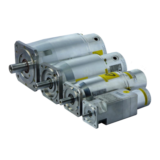
All informations and datas are avaible on : http://www.parker.com/eme/ex 2.2. Overview The EX servomotors from Parker are specifically designed to operate in explosive atmospheres for industrial applications. The EX motors are brushless synchronous servomotors, with permanent magnets, based on NX active parts. -
Page 38: General Technical Data For Atex/Iecex Motors
2.4. General Technical Data for ATEX/IECEx motors EX3, EX4, EX6 Motor type Permanent-magnet synchronous motor Magnets material Neodymium Iron Boron Number of poles Type of IMB5 – IMV1 – IMV3 (EN60034-7) construction • Gazeous atmosphere : IP64 on request, IP65 Degree of •... -
Page 39: General Technical Data For Ul Motors
2.5. General Technical Data for UL motors EX3, EX4, EX6 Motor type Permanent-magnet synchronous motor Magnets material Neodymium Iron Boron Number of poles Type of IMB5 – IMV1 – IMV3 (CEI 60034-7) construction Degree of IP65 protection Cooling Natural cooling Rated voltage 230VAC, 400 VAC, 480 VAC Insulation of the... -
Page 40: Product Code
2.6. Product Code The EX servomotors are defined by its electrical and mechanical characteristics, by its accompanying accessories and by any customer specificity. This information is coded and entered in the “Type” column on the manufacturer’s plate for the basic codification; the specificities are entered in a separate column (Check option available for each certification). -
Page 41: Technical Data
EX servomotors are designed to operate with a maximum ambient temperature of 40°C. In case of using with an ambient temperature above 40°C and less or equal than 60°C, a derating of performances is applied according to data recommended by Parker. 3.1.4. - Page 42 Illustration : Acceleration-deceleration torque: 10 Nm for 0,1 s. Resistant torque: 1 Nm during all the movement. 2800 rpm during 0,2 s. Max-min speed: Max torque provided by the motor: 11 Nm. rms torque: 6 Nm. 4000 3000 2000 1000 Time [s] -1000...
-
Page 43: Servo Drive Selection
Furthermore, each Mi and speed associated Ωi of the duty cycle has to be located in the operational area of the torque vs speed curve. Torque rms. Ωi Ωk Ω Ωn Speed 3.1.5. Servo drive selection Selection of drive depends on its rated power, rated current and its mode selection which leads to the maximal current duration. - Page 44 AC890 PARKER drive example: The rated current provided by the AC890 drive depends on its rated power and its mode selection. “Vector mode” is used for induction motors while “Servo mode” is used for brushless AC motors. With EX motors the power is usually < 37 kW, the rated current corresponds to 100 %.
- Page 45 Example n°1 : The application needs: - a rms torque of 7 Nm at the rms speed of 2000 rpm, - an acceleration torque of - a maximal speed of 2800 rpm. Selection of the motor: The selected motor is the type EX620EAO. The nominal speed is equals to 4300 rpm.
- Page 46 Example n°2 : This times; the application needs : - a permanent torque of 5 Nm at low speed, - a rms torque of 5 Nm at the rms speed of 1890 rpm, - an acceleration torque of 7.6 Nm, - a maximal speed of 2800 rpm.
-
Page 47: Current Limitation At Stall Conditions (I.e. Speed < 3 Rpm)
3.1.6. Current limitation at stall conditions (i.e. speed < 3 rpm) Recommended reduced current at speed < 3 rpm: reduced Warning: The current must be limited to the prescribed values. If the nominal torque has to be maintained at stop or low speed (< 3 rpm), imperatively limit the current to 70% of I (permanent current at low speed), in order to avoid an excessive overheating of the motor. -
Page 48: Ex Characteristics: Torque, Speed, Current, Power
3.2. EX Characteristics: Torque, speed, current, power… The torque vs speed graph below explains different intrinsic values of the next tables. Torque Peak Torque Permanent Rated Low Speed Power Torque Rated torque Stall torque 3 rpm Rated Speed speed speed 48 –... -
Page 49: Atex/Iecex 230V
3.2.1. ATEX/IECEx 230V Rated Rated Rated Rated Peak Peak Max. Speed speed Power Torque Speed Current Torque Current Speed Torque Current Motor Mpeak I peak Nmax (kW) (Nm) [rpm] [Arms] [Nm] [Arms] [Nm] [Arms] [rpm] With 40°C ambiant temperature EX310EAP 0.40 1.66 2300... -
Page 50: Atex/Iecex 400V
3.2.2. ATEX/IECEx 400V Rated Rated Rated Rated Peak Peak Max. Speed speed Power Torque Speed Current Torque Current Speed Torque Current Motor Mpeak I peak Nmax (kW) (Nm) [rpm] [Arms] [Nm] [Arms] [Nm] [Arms] [rpm] With 40°C ambiant temperature EX310EAP 0.64 1.54 4000... -
Page 51: Ul 230V
3.2.3. UL 230V Rated Rated Rated Rated Peak Peak Max. Speed speed Power Torque Speed Current Torque Current Speed Torque Current Motor Mpeak I peak Nmax (kW) (Nm) [rpm] [Arms] [Nm] [Arms] [Nm] [Arms] [rpm] With 40°C ambiant temperature EX310UAU 0.62 4200 1.60... -
Page 52: Further Data
3.2.5. Further Data Motor Moment of Winding Polarity Thermal Inductance Inertia Motor Resistance Time [Nm/Arms] [Vrms/krpm] [mH] [ohms] Constant tth [kgmm²] ATEX / IECEx EX310EAP 1.42 88.9 20.7 55.9 EX310EAK 0.81 50.9 20.3 6.58 57.7 EX420EAP 1.42 EX420EAJ 0.821 51.4 2.31 73.7 EX430EAL... -
Page 53: Efficiency Curves
3.2.6. Efficiency curves Caution: The efficiency curves are typical values. They may vary from one motor to an other Caution: The efficiency curves are given for an optimal motor control (no voltage saturation and optimal phase between current and EMF) Caution: The efficiency curves do not include the losses due to the switching frequency. - Page 54 3.2.6.1. Series EX310E (EX310EAP) Constant efficiency curves of the motor EX310E Efficiency [%] 1000 1500 2000 2500 3000 3500 4000 Speed [rpm] 54 – Pvd3665_Gb_Ex_August 2022...
-
Page 55: Series Ex420E (Ex420Eap)
3.2.6.2. Series EX420E (EX420EAP) Constant efficiency curves of the motor EX420E Efficiency [%] 1000 1500 2000 2500 3000 3500 4000 Speed [rpm] 3.2.6.3. Series EX430E (EX430EAL) Constant efficiency curves of the motor EX430E Efficiency [%] 74 76 1000 1500 2000 2500 3000 3500... -
Page 56: Series Ex620E (Ex620Eao)
3.2.6.4. Series EX620E (EX620EAO) Constant efficiency curves of the motor EX620E Efficiency [%] 1000 1500 2000 2500 3000 3500 4000 Speed [rpm] 3.2.6.5. Series EX630E (EX630EAN) Constant efficiency curves of the motor EX630E Efficiency [%] 1000 1500 2000 2500 3000 3500 4000 Speed [rpm]... -
Page 57: Series Ex820E (Ex820Ear)
3.2.6.6. Series EX820E (EX820EAR) Constant efficiency curves of the motor EX820E Efficiency [%] 1000 1500 2000 2500 3000 3500 Speed [rpm] 3.2.6.7. Series EX840E (EX840EAK) Constant efficiency curves of the motor EX840E Efficiency [%] 1000 1500 2000 2500 3000 Speed [rpm] 57 –... -
Page 58: Series Ex860E (Ex860Eaj)
3.2.6.8. Series EX860E (EX860EAJ) Constant efficiency curves of the motor EX860E Efficiency [%] 1000 1500 2000 2500 Speed [rpm] 58 – Pvd3665_Gb_Ex_August 2022... -
Page 59: Series Ex310U (Ex310Uau)
3.2.6.9. Series EX310U (EX310UAU) Constant efficiency curves of the motor EX310U Efficiency [%] 1000 2000 3000 4000 5000 6000 7000 Speed [rpm] 59 – Pvd3665_Gb_Ex_August 2022... -
Page 60: Series Ex420U (Ex420Uai)
3.2.6.10. Series EX420U (EX420UAI) Constant efficiency curves of the motor EX420U Efficiency [%] 1000 2000 3000 4000 5000 6000 7000 Speed [rpm] 3.2.6.11. Series EX430U (EX430UAG) Constant efficiency curves of the motor EX430U Efficiency [%] 1000 2000 3000 4000 5000 Speed [rpm] 60 –... -
Page 61: Series Ex620U (Ex620Uam)
3.2.6.12. Series EX620U (EX620UAM) Constant efficiency curves of the motor EX620U Efficiency [%] 1000 1500 2000 2500 3000 3500 4000 4500 5000 Speed [rpm] 3.2.6.13. Series EX630U (EX630UAK) Constant efficiency curves of the motor EX630U Efficiency [%] 1000 1500 2000 2500 3000 3500... -
Page 62: Series Ex820U (Ex820Uaq)
3.2.6.14. Series EX820U (EX820UAQ) Constant efficiency curves of the motor EX820U Efficiency [%] 1000 1500 2000 2500 3000 3500 4000 Speed [rpm] 3.2.6.15. Series EX840U (EX840UAL) Constant efficiency curves of the motor EX840U Efficiency [%] 1000 1500 2000 2500 3000 Speed [rpm] 62 –... -
Page 63: Series Ex860U (Ex860Uaj)
3.2.6.16. Series EX860U (EX860UAJ) Constant efficiency curves of the motor EX860U Efficiency [%] 1000 1500 2000 2500 Speed [rpm] 63 – Pvd3665_Gb_Ex_August 2022... -
Page 64: Electromagnetic Losses
3.2.7. Electromagnetic losses Caution: Following data result from our best estimations but are indicative. They can vary from one motor to another and with temperature. No responsibility will be accepted for direct or indirect losses or damages due to the use of these data. (Following data are indicative, without lip seal, IP64 motor) Type Tf [Nm]... -
Page 65: Time Constants Of The Motor
3.2.8. Time constants of the motor 3.2.8.1. Electric time constant: elec With following values given in the motor data sheet inductance of the motor phase to phase [H], ph_ph resistance of the motor phase to phase at 25°C [Ohm]. ph_ph Example: Motor series EX620EAO... -
Page 66: Thermal Time Constant Of The Copper
Remarks: For a DC motor, the mechanical time constant represents the duration needed to mech reach 63% of the final speed when applying a voltage step without any resistant torque. However this value makes sense only if the electric time constant is much smaller than elec ... -
Page 67: Speed Ripple
(neither external inertia nor resistant torque). 3.2.10. Cogging torque The typical cogging for a EX series below is the maximum value peak to peak in N.cm: Cogging Maxi Motor [N.cm]... -
Page 68: Rated Data According To Rated Voltage Variation
3.2.11. Rated data according to rated voltage variation The nominal characteristics and especially the rated speed, maximal speed, rated power, rated torque, depend on the nominal voltage supplying the motor considered as the rated voltage. The rated data mentioned in the data sheet are given for each association of motor and drive. - Page 69 Maximum speed: The former maximum speed N = 3000 rpm obtained with U =400 V and a speed N =3000 rpm leads to the new maximum speed N given as follows: max2 2674 3000 2674 3000 N.B. If the rated voltage increases (U >...
-
Page 70: Voltage Withstand Characteristics Of Ex Series
3.2.12. Voltage withstand characteristics of EX series The motors fed by converters are subject to higher stresses than in case of sinusoidal power supply. The combination of fast switching inverters with cables will cause overvoltage due to the transmission line effects. The peak voltage is determined by the voltage supply, the length of the cables and the voltage rise time. -
Page 71: Voltage And Current During The Operating
3.2.13. Voltage and current during the operating The EX motors can carry ATEX, IECEx, CCC and UL certification and due to this certificate, they are subjected to strict rules regarding their use. One of such rules is the us of a servoamplifier that meets specific characteristics. - Page 72 EX310 UL : Voltage of the associated speed 230V single / three phases 400-480V three phases drive Nominal Power supply direct current 310 ±10% 550-660 ±10% voltage(v) Motor electrical frequency (Hz) 0 to 650 0 to 650 Steady peak current in a phase Max.
-
Page 73: Dimension Drawings
3.3. Dimension drawings 3.3.1. EX310E 73 – Pvd3665_Gb_Ex_August 2022... -
Page 74: Ex420E Ex430E
3.3.2. EX420E EX430E 74 – Pvd3665_Gb_Ex_August 2022... -
Page 75: Ex620E Ex630E
3.3.3. EX620E EX630E 75 – Pvd3665_Gb_Ex_August 2022... -
Page 76: Ex820E Ex840E Ex860E
3.3.4. EX820E EX840E EX860E 76 – Pvd3665_Gb_Ex_August 2022... -
Page 77: Ex310
EX310…C (CCC) 3.3.5. 77 – Pvd3665_Gb_Ex_August 2022... -
Page 78: Ex420
EX420…C; EX430…C (CCC) 3.3.6. 78 – Pvd3665_Gb_Ex_August 2022... -
Page 79: Ex620
EX620…C; EX630…C (CCC) 3.3.7. 79 – Pvd3665_Gb_Ex_August 2022... -
Page 80: Ex820
EX820…C; EX820…C; EX820…C (CCC) 3.3.8. 80 – Pvd3665_Gb_Ex_August 2022... -
Page 81: Ex310U
3.3.9. EX310U 81 – Pvd3665_Gb_Ex_August 2022... -
Page 82: Ex420U Ex430U
3.3.10. EX420U EX430U 82 – Pvd3665_Gb_Ex_August 2022... -
Page 83: Ex620U Ex630U
3.3.11. EX620U EX630U 83 – Pvd3665_Gb_Ex_August 2022... -
Page 84: Ex820U Ex840U Ex860U
3.3.12. EX820U EX840U EX860U 84 – Pvd3665_Gb_Ex_August 2022... -
Page 85: Motor Mounting
3.4. Motor Mounting 3.4.1. Motor mounting By flange in any direction 3.4.2. Installation of ATEX machines Keep in mind that EX motors are equipments with protect mode “db” flameproof enclosure for hazardous area of gas and with protection by enclosure "tb" for hazardous area of dust ignition. -
Page 86: Frame Recommendation
3.4.3. Frame recommendation Warning : The user has the entire responsibility to design and prepare the support, the coupling device, shaft line alignment, and shaft line balancing. Foundation must be even, sufficiently rigid and shall be dimensioned in order to avoid vibrations due to resonances. -
Page 87: Shaft Loads
3.5. Shaft Loads 3.5.1. Vibration resistance to shaft end Frequency domain :10 to 55 Hz according to EN 60068 -2-6 Vibration resistance to the shaft end : - radial 3 g - axial 1 g 3.5.2. Maximum load acceptable on the shaft Warning : The values written in the table are given for a load placed on the middle of the shaft like the picture below. - Page 88 Warning : Regarding to these shaft loads, you must’nt use a pulley belt system without a load take-up system. Type Maximum shaft load F [N] EX310 EX430 EX630 EX860 88 – Pvd3665_Gb_Ex_August 2022...
-
Page 89: Cooling
3.6. Cooling In compliance with the IEC 60034-1 standards: The ambient air temperature shall not be less than -20°C and more than 40°C. It is possible to use the motors in an higher ambient temperature between 40°C to 60°C but with an associated derating to the motor performances. Warning: To reach the motor performances calculated, the motor must be thermally well connected to a aluminium flange with a dimension of 400 mm x 400 mm and with a thickness of 12 mm. -
Page 90: Thermal Protection
3.7. Thermal Protection The drive guarantees a 1st level of safety but it is not sufficient. Safety is guaranteed by the independent relay system described in the connection diagram (§4.3.3) which constitutes an independent protection circuit meeting safety classification SIL2 in accordance with the standard IEC 61508. -
Page 91: Power Electrical Connections
The informations of these cable glands are placed in the §4.4. The cable gland expected for the feedback cable could be replace by an ATEX thread cap in case of a servomotor in sensorless. It is forbidden to change a cable gland without the Parker agreement. 3.8.2. Wires sizes In every country, you must respect all the local electrical installation regulations and standards. -
Page 92: Conversion Awg/Kcmil/Mm²
Please contact PARKER for further information. Caution: It might be necessary to fit a filter at the servo-drive output if the length of the cable exceeds 25 m. -
Page 93: Mains Supply Connection Diagrams
3.8.5. Mains supply connection diagrams 3.8.5.1. EX310E 93 – Pvd3665_Gb_Ex_August 2022... -
Page 94: Ex420E, Ex430E
3.8.5.2. EX420E, EX430E 94 – Pvd3665_Gb_Ex_August 2022... -
Page 95: Ex620E, Ex630E
3.8.5.3. EX620E, EX630E 95 – Pvd3665_Gb_Ex_August 2022... -
Page 96: Ex820E, Ex840E, Ex860E
3.8.5.4. EX820E, EX840E, EX860E 96 – Pvd3665_Gb_Ex_August 2022... -
Page 97: Ex310
EX310…C (CCC) 3.8.5.5. 97 – Pvd3665_Gb_Ex_August 2022... -
Page 98: Ex420
EX420…C; EX430…C (CCC) 3.8.5.6. 98 – Pvd3665_Gb_Ex_August 2022... -
Page 99: Ex620
EX620…C; EX630…C (CCC) 3.8.5.7. 99 – Pvd3665_Gb_Ex_August 2022... -
Page 100: Ex820
EX820…C; EX840…C; EX860…C (CCC) 3.8.5.8. 100 – Pvd3665_Gb_Ex_August 2022... -
Page 101: Ex310U
3.8.5.9. EX310U 101 – Pvd3665_Gb_Ex_August 2022... -
Page 102: Ex420U, Ex430U
3.8.5.10. EX420U, EX430U 102 – Pvd3665_Gb_Ex_August 2022... -
Page 103: Ex620U, Ex630U
3.8.5.11. EX620U, EX630U 103 – Pvd3665_Gb_Ex_August 2022... -
Page 104: Ex820U, Ex840U, Ex860U
3.8.5.12. EX820U, EX840U, EX860U 104 – Pvd3665_Gb_Ex_August 2022... -
Page 105: Atex/Iecex Motor Connection
3.8.6. ATEX/IECEx motor connection 3.8.6.1. Connection of the power and the feedback cables with terminals Step 1 – Remove the rear cover : 1. Unscrew the nuts for the EX3-EX4-EX6 and the screws for the EX8 Ref 1. 2. Unscrew the cable gland caps Ref 2. 3. - Page 106 Step 3 – Connection of the power cable : 1. Insert the cable in the cable gland Ref 2. 2. Strip the wires on 3 mm. 3. Put the wires U, V, W, Ground, TH+ and TH- and also BR+ and BR- in a case of a motor with a brake in the terminal of the PCB Ref 4 and tighten each screws at the torque value of 0,6N.m.
-
Page 107: Connection Of The Feedback And Power Cable With Connector On Ex3
3.8.6.2. Connection of the feedback and power cable with connector on EX3 : Step 1 – Remove the rear cover : 1. Unscrew the 4 nuts Ref 1. 2. Unscrew the cable gland caps Ref 2. 3. Remove the cover Ref 3. Step 2 –... - Page 108 Step 4 – Fitting of the rear cover : 1. Slowly take up any slack in the cables and close the cover Ref 3. 2. Tighten the cable gland caps Ref 2 at the torque value of : Cable gland size Torque (N.m) 12,5 3.
-
Page 109: Ex3-Ex4 Ul Connection
3.8.7. EX3-EX4 UL connection 3.8.7.1. Connection of the feedack and power cable with connector: Step 1 – Remove the rear cover: 1. Unscrew the 4 nuts Ref 1. 2. Unscrew the cable gland caps Ref 2. 3. Remove the cover Ref 3. Step 2 –... - Page 110 Step 3 – Connection of the power cable : 1. Insert the cable in the cable gland or conduit stop Ref 2. 2. Strip the wires on 5mm and crimp the wires U, V, W and Ground in the faston terminals 6,8x0,8.
-
Page 111: Ex6-Ex8 Ul Connection
3.8.8. EX6-EX8 UL connection 3.8.8.1. Connection of the feedack and power cable with terminal: Step 1 – Remove the rear cover : 1. Unscrew the 4 nuts Ref 1. 2. Unscrew the cable gland caps Ref 2. 3. Remove the cover Ref 3. Step 2 –... - Page 112 Step 3 – Connection of the power cable : 1. Insert the cable in the cable gland Ref 2. 2. Strip the wires on 3 mm. 3. Put the wires U, V, W, Ground, TH+ and TH- and also BR+ and BR- in a case of a motor with a brake in the terminal of the PCB Ref 4 and tighten each screws at the torque value of 0,6N.m.
-
Page 113: Feedback System
With the connection explained in the documentation and with a positive speed request on the drive, the shaft will turn in clockwise direction (see customer shaft end). Resolver 2 poles transformation ratio = 0.5 – code A 3.8.11. EX4, EX6 & EX8 Parker part number 220005P1001 220005P1002 Electrical specification Values @ 8 kHz... -
Page 114: Hiperface Encoder Singleturn Eks3618 Bits- Code P
3.8.13. Hiperface encoder singleturn EKS3618 bits– code P EX3, EX4, EX6 & EX8 Model EKS36-2KF0B018A (Sick) Type Absolute single turn encoder Parker part number 220174P0011 Electrical interface Hiperface DSL Position values per 18 bits revolution Revolutions count Error limits for the digital ±... -
Page 115: Hiperface Encoder Singleturn Sks36 (128Pulses) - Code R
Hiperface encoder singleturn SKS36 (128pulses) – code R 3.8.15. EX3, EX4, EX6 & EX8 Model SKS36S-HFA0-K02 (Sick) Type Absolute single turn encoder Parker part number 220174P0015 Line count 128 sine/cosine periods per revolution Electrical interface Hiperface Position values per 4096... -
Page 116: Cables
3.9. Cables You can connect EX motors to PARKER servo drives : AC30, AC890, COMPAX3, PSD or SLVD. You can use complete cable with part number on the tabs below. The "xxx" in the part number must be replaced by the length in meter with a minimal length of 3m. -
Page 117: Cable Option Max 80°C On The Surface Atex/Iecex
Size EX4 : EX4 certified for an ambient temperature of -20 to +60°C Ambient temperature for a Parker -20 to +60°C standard cable using (Max 100°C) Ambient temperature for an using of cables withstanding a max temperature -20 to +49°C... -
Page 118: Power & Sensor Cable For Psd
3.9.2. Power & Sensor cable for PSD Cable for use with Hiperface DSL® feedback (single cable reference 100°C) : Current - 12 A @40°C ambient t° Drive Current - 9 A @60°C ambient t° PSD1S, PSD1M18 CBM015TD-T03-D01-xxxx-00 PSD1M (except M18) CBM015TD-T03-D02-xxxx-00 (xxxx for length : 0100 = 10m) Cable arrangement :... - Page 119 Sensor cable for use with resolver feedback (Cable reference 100°C) : CBFRE0T0-T05-D03-xxxx-00 (xxxx for length : 0100 = 10m) Cable Arrangement : EX Motor 15 pins Male identification Wire colour Terminals SuB-D HD Cosine + S1 Black / White Sine + S2 Black / Blue Cosine - S3 White...
-
Page 120: Brake Option
3.10. Brake option Caution: The holding brake is used to completely immobilize the servomotor under load. It is not designed to be used for repeated dynamic braking ; dynamic braking must only be used in the case of an emergency stop and with a limited occurance depending on the load inertia and speed. -
Page 121: Commissioning, Use And Maintenance
4. COMMISSIONING, USE AND MAINTENANCE 4.1. Instructions for commissioning, use and maintenance 4.1.1. Equipment delivery All servomotors are strictly controlled during manufacturing, before shipping. While receiving it, it is necessary to verify motor condition and if it has not been damaged in transit. -
Page 122: Storage
4.1.3. Storage Before being mounted, the motor has to be stored in a dry place, without rapid or important temperature variations in order to avoid condensation. During storage, the ambient temperature must be kept between -20 and +60°C. If the torque motor has to be stored for a long time, verify that the shaft end, feet and the flange are coated with corrosion proof product. -
Page 123: Preparation
4.2.3. Preparation Once the motor is installed, it must be possible to access the wiring, and read the manufacturer’s plate. Air must be able to circulate around the motor for cooling purposes. Clean the shaft using a cloth soaked in white spirit or alcohol. Pay attention that the cleaning solution does not get on to the bearings. -
Page 124: Electrical Connections
Warning : a misalignment of the coupling device makes stress and load on the motor shaft depending the rigidity of the installation. The variations of the temperature makes stress and load due to the dilatation. These loads (axials and radiale) do not exceed the load written (§... -
Page 125: Cable Connection
4.3.1. Cable connection Please, read §3.8 "Electrical connection" to have information about cable connection Many useful informations are already available in the drive documentations. 4.3.2. Encoder cable handling Danger: before any intervention the drive must be stopped in accordance with the procedure. Caution: It is forbidden to disconnect the Encoder cable under voltage (high risk of damage and sensor destruction). -
Page 126: Connection Diagrams
4.3.3. Connection diagrams 4.3.3.1. EX3-EX4 DC supply 4.3.3.2. EX single phase 126 – Pvd3665_Gb_Ex_August 2022... -
Page 127: Ex Three Phase
4.3.3.3. EX three phase The safe torque off function is an alternative solution for the motor temperature monitoring. The safe torque off function in accordance with the standards EN ISO 13849-1 : 2006 and EN 61800-5-2 : 2006 is an electronic system set up on some drives certified by a notified body. -
Page 128: Cable Glands Informations (Only Atex/Iecex)
4.3.4. Cable glands informations (Only ATEX/IECEx) 4.3.4.1. Technical data 128 – Pvd3665_Gb_Ex_August 2022... -
Page 129: Torque Value
4.3.4.2. Torque value M16 Cable glands ADE N°5 : Torque value for the cap = 12,5 N.m Torque value for the connection module = 0,5 N.m M20 Cable gland ADE N°6 : Torque value for the cap = 20 N.m Torque value for the connection module = 0,5 N.m 129 –... -
Page 130: Ul Electrical Commissioning
Warning : Installers use any wiring other than that shown in the diagrams in §4.3.3. “Connection diagrams” at their own risk; Parker cannot be held responsible for unauthorized wiring. Make sure that the characteristics of the contactors shown in these... -
Page 131: Maintenance Operations
VDE 0105 or IEC 0364) and local regulations. They must be authorized to install, commission and operate in accordance with established practices and standards. Please contact PARKER for technical assistance. Danger: before any intervention the motor must be disconnected from te power supply. -
Page 132: Informations About The Flameproof Enclosure Components
4.4.2. Informations about the flameproof enclosure components The Ex motors of Parker Hannifin France has a traceability on the frameprood enclosure compotents. It is forbidden to replace on of these components without consulting Parker Hannifin. If a cover exchange between two identical motors is required, the customer must make a new traceability on these components. -
Page 133: Troubleshooting
Some symptoms and their possible causes are listed below. This list is not comprehensive. Whenever an operating incident occurs, consult the relevant servo drive installation instructions (the troubleshooting display indications will help you in your investigation) or contact us at: http://www.parker.com/eme/repairservice. • You note that the motor...
Need help?
Do you have a question about the EX Series and is the answer not in the manual?
Questions and answers