
Related Manuals for Parker EY Series


Summary of Contents for Parker EY Series
- Page 1 Servomotors EY Series Technical Manual Preliminary PVD 3675 - EY 1 – Pvd3675_Gb_Ey_July 2024...
- Page 2 2 – Pvd3675_Gb_Ey_July 2024...
- Page 3 3 – Pvd3675_Gb_Ey_July 2024...
- Page 4 4 – Pvd3675_Gb_Ey_July 2024...
- Page 5 5 – Pvd3675_Gb_Ey_July 2024...
- Page 6 6 – Pvd3675_Gb_Ey_July 2024...
-
Page 7: Table Of Contents
Time constants of the motor ................... 29 3.2.5. Speed ripple ........................31 3.2.6. Cogging torque ....................... 31 3.2.7. Voltage withstand characteristics of EY series .............. 31 3.2.8. Maximum speed to respect minimum airgap ..............32 3.2.9. Voltage and current during operating ................33 3.3. - Page 8 COMMISSIONING, USE AND MAINTENANCE ................53 4.1. Instructions for commissioning, use and maintenance ............53 4.1.1. Equipment delivery ......................53 4.1.2. Handling ......................... 53 4.1.3. Storage ........................... 54 4.2. Installation ..........................54 4.2.1. Mounting ......................... 54 4.2.2. Torque value for the screws ................... 54 4.2.3.
-
Page 9: Introduction
Reading and understanding the information described in this document is mandatory before carrying out any operation on the motors. If any malfunction or technical problem occurs, that has not been dealt with in this manual, please contact PARKER for technical assistance. In case of missing information or doubts regarding the installation procedures, safety instructions or any other issue tackled in this manual, please contact PARKER as well. -
Page 10: Safety
1.2. Safety 1.2.1. Principle To operate safely, this equipment must be transported, stored, handled, installed and serviced correctly. Following the safety instructions described in each section of this document is mandatory. Servomotors usage must also comply with all applicable standards, national directives and factory instructions in force. DANGER: Non-compliance with safety instructions, legal and technical regulations in force may lead to physical injuries or death, as well as damages to the property and the environment. - Page 11 Mechanical hazard Servomotors can accelerate in milliseconds. Running the motor can lead to other sections of the machine moving dangerously. Moving parts must be screened off to prevent operators coming into contact with them. The working procedure must allow the operator to keep well clear of the danger area.
-
Page 12: Operating Category And Marking Of Ey Servomotors
1.2.3. Operating category and marking of EY servomotors 1.2.3.1. ATEX gazeous atmospheres II 3 G Ex ec IIC T3 Gc IP65 IP65 Very high Equipment Very high T1 450 °C level of with protection level of protection against sparks protection Methane Equipment High level of... - Page 13 1.2.3.2. ATEX dusty atmospheres II 3 GD Ex ec IIC T3 Gc IP65 / Ex tc IIIC T200°C Dc IP65 T200 °C IP65 Very high Very high Protection by T1 450 °C level of level of enclosure protection protection Combustible flying tb / tc High level of...
- Page 14 1.2.3.3. CCC Certified motors The CCC EY motors are verified and certified according to CNCA-C23-01: 2024 China Compulsory Certification Implementation Rule on Explosion Protected Electrical Product and the SITIIAS-C23-01-2023. The reference standard are : GB/T 3836.1-2021; GB/T 3836.3-2021; GB/T 3836.31-2021. CCC: "CCC"...
-
Page 15: Product Description
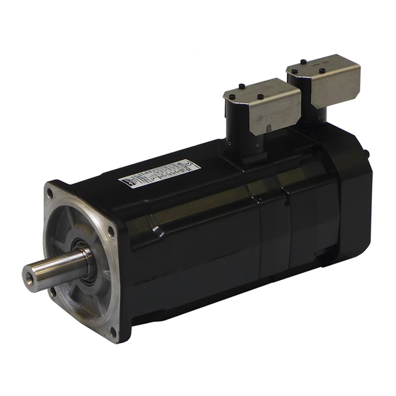
All informations and data are avaible on : http://www.parker.com/eme/ey 2.2. Overview The EY servomotors from Parker are specifically designed to operate in explosive atmospheres for industrial applications. The EY motors are brushless synchronous servomotors, with permanent magnets, based on NX active parts. -
Page 16: General Technical Data For Atex Motors
2.4. General Technical Data for ATEX motors EY3, EY4, EY6 Motor type Permanent-magnet synchronous motor Neodymium Iron Boron (Nd-Fe-B) Magnets material Number of poles IMB5 – IMV1 – IMV3 (CEI 60034-7) Type of construction Degree of IP65 protection Cooling Natural cooling 230 VAC, 400 VAC Rated voltage Class F according to... -
Page 17: Product Code
Motor length Motor version ATEX / CCC motor Feedback sensor resolver 2 poles transformation ratio = 0.5 Without sensor Without sensor and Parker AC drive A, B... to Z Torque speed characteristics See motor data sheet Painting Black painting RAL9005... -
Page 18: Technical Data
20, 40, 60 Motor version ATEX / CCC motor Feedback sensor resolver 2 poles transformation ratio = 0.5 Without sensor Without sensor and Parker AC drive Torque speed characteristics A, B... to Z See motor data sheet Painting Black painting RAL9005... - Page 19 Let us consider: - the period of the cycle T [s], - the successively samples of movements i characterized each ones by the maximal torque M [Nm] reached during the duration [s]. So, the rms torque M can be calculated through the following basic formula : ...
- Page 20 Illustration : Acceleration-deceleration torque: 10 Nm for 0,1 s. Resistant torque: 1 Nm during all the movement. 2800 rpm during 0,2 s. Max-min speed: Max torque provided by the motor: 11 Nm. rms torque: 6 Nm. 4000 3000 2000 1000 Time [s] -1000...
-
Page 21: Servo Drive Selection
Furthermore, each Mi and speed associated Ωi of the duty cycle has to be located in the operational area of the torque vs speed curve. Torque rms. Ωi Ωk Ω Ωn Speed 3.1.6. Servo drive selection : Selection of drive depends on its rated power, rated current and its mode selection which leads to the maximal current duration. - Page 22 AC30 PARKER drive example: With EY servomotors, the power is usually < 37 kW, the rated current corresponds to 100 %. Power of servo drive AC30 < 37 kW Mode Servo Overload capability [%] 200 % during 4 s Illustration:...
- Page 23 Example : The application needs: - a rms torque of 6 Nm at the rms speed of 4000 rpm, - an acceleration torque of 25 Nm, - a maximal speed of 4000 rpm. Selection of motor: The selected motor is the type EY630EAN. The nominal speed is equals to 4000 rpm.
-
Page 24: Current Limitation At Stall Conditions (I.e. Speed < 3 Rpm)
3.1.7. Current limitation at stall conditions (i.e. speed < 3 rpm) Recommended reduced current at speed < 3 rpm: reduced Warning: The current must be limited to the prescribed values. If the nominal torque has to be maintained at stop or low speed (< 3 rpm), imperatively limit the current to 70% of I (permanent current at low speed), in order to avoid an excessive overheating of the motor. -
Page 25: Ey Characteristics: Torque, Speed, Current, Power
3.2. EY Characteristics: Torque, speed, current, power… The torque vs speed graph below explains different intrinsic values given in next tables. Torque Peak Torque Permanent Rated Low Speed Power Torque Rated torque Stall torque 3 rpm Rated Speed speed speed 25 –... -
Page 26: Atex 230V
3.2.1. ATEX 230V Rated Rated Rated Rated Peak Peak Max. Speed speed Power Torque Speed Current Torque Current Speed Motor Torque Current Mpeak I peak Nmax (kW) (Nm) [rpm] [Arms] [Nm] [Arms] [rpm] [Nm] [Arms] With 40°C ambiant temperature 0.456 1.89 2300 1.37... -
Page 27: Atex 400V
3.2.2. ATEX 400V Rated Rated Rated Rated Peak Peak Max. Speed speed Power Torque Speed Current Torque Current Speed Motor Torque Current Mpeak I peak Nmax (kW) (Nm) [rpm] [Arms] [Nm] [Arms] [rpm] [Nm] [Arms] With 40°C ambiant temperature 0.718 1.71 4000 1.26... -
Page 28: Electromagnetic Losses
3.2.3. Electromagnetic losses Caution: Following data result from our best estimations but are indicative. They can vary from one motor to another and with temperature. No responsibility will be accepted for direct or indirect losses or damages due to the use of these data. Following data are indicative, without any friction coming from lip seals. -
Page 29: Time Constants Of The Motor
3.2.4. Time constants of the motor 3.2.4.1. Electric time constant : elec With following values given in the motor data sheet inductance of the motor phase to phase [H], ph_ph resistance of the motor phase to phase at 25°C [Ohm]. ph_ph Example: Motor series EY630EAN... - Page 30 Remarks : For a DC motor, the mechanical time constant represents the duration needed mech to reach 63% of the final speed when applying a voltage step without any resistant torque. However this value makes sense only if the electric time constant is much elec ...
-
Page 31: Speed Ripple
(neither external inertia nor resistant torque) 3.2.6. Cogging torque The typical cogging for a EY series below is the maximum value peak to peak in N.cm: Cooging Maxi Motor [N.cm]... -
Page 32: Maximum Speed To Respect Minimum Airgap
MOTOR PULSE WITHSTAND CHARACTERISTIC CURVES Curve EY motors Curve IEC 60034-25: <690V AC Curve IEC 60034-25: <500V AC Curve IEC 60034-17: <500V AC Voltage Pulse Rise Time (µs) Figure 1: Minimum Voltage withstands characteristics for motors insulations according to IEC standards. At the top are the typical capabilities for the EY motors. Note: The pulse rise times are defined in accordance with standards IEC/TS 60034-17 ed4.0 2006-05-09. -
Page 33: Voltage And Current During Operating
3.2.9. Voltage and current during operating EY motors present an ATEX certification and due to this certificate are subjected to strict rules regarding their use. One of such rules is the use of a servoamplifier that meets specific characteristics.These characteristics are valid for an ambient temperature comprised between -20°C and 40°C. -
Page 34: Outline Drawings
3.3. Outline drawings 3.3.1. EY310E 34 – Pvd3675_Gb_Ey_July 2024... -
Page 35: Ey420E Ey430E
3.3.2. EY420E EY430E 35 – Pvd3675_Gb_Ey_July 2024... -
Page 36: Ey620E Ey630E
3.3.3. EY620E EY630E 36 – Pvd3675_Gb_Ey_July 2024... -
Page 37: Ey820E Ey840E Ey860E
3.3.4. EY820E EY840E EY860E 37 – Pvd3675_Gb_Ey_July 2024... -
Page 38: Motor Mounting
3.4. Motor mounting 3.4.1. Motor mounting By flange in any direction. 3.4.2. Installation of ATEX machines Keep in mind that EY motors are equipments with protect mode "nA" non sparking for hazardous area of gas and with protection by enclosure "tc" for hazardous area of dust ignition. -
Page 39: Frame Recommendation
3.4.3. Frame recommendation Warning : The user has the entire responsibility to design and prepare the support, the coupling device, shaft line alignment, and shaft line balancing. Foundation must be even, sufficiently rigid and shall be dimensioned in order to avoid vibrations due to resonances. -
Page 40: Shaft Loads
3.5. Shaft Loads 3.5.1. Vibration resistance toshaft end Frequency domain :10 to 55 Hz according to EN 60068 -2-6 Vibration resistance to the shaft end : - radial 3 g - axial 1 g 3.5.2. Maximum load acceptable on the shaft Notice: Curves below are valid only for horizontal mounting and a life time L10 of 20 000h at constant speed in accordance with ISO281. - Page 41 3.5.2.2. EY420 3.5.2.3. EY430 41 – Pvd3675_Gb_Ey_July 2024...
- Page 42 3.5.2.4. EY620 3.5.2.5. EY630 42 – Pvd3675_Gb_Ey_July 2024...
- Page 43 3.5.2.6. EY820 3.5.2.7. EY840 43 – Pvd3675_Gb_Ey_July 2024...
- Page 44 3.5.2.8. EY860 44 – Pvd3675_Gb_Ey_July 2024...
-
Page 45: Cooling
3.6. Cooling In compliance with the IEC 60034-1 standards: The ambient air temperature shall not be less than -20°C and more than 40°C. It is possible to use the motors in an higher ambient temperature between 40°C to 60°C but with an associated derating to the motor performances. -
Page 46: Thermal Protection
3.7. Thermal Protection The protection against thermal overloading of the motor is a PTC thermistors (as standard) built into the stator winding. The thermal sensor, due to their thermal inertia, are unable to follow very fast winding temperature variations. They acheive their thermal steady state after a few minutes. -
Page 47: Power Electrical Connections
3.8. Power Electrical Connections 3.8.1. Wires sizes In every country, you must respect all the local electrical installation regulations and standards. Not limiting example in France: NFC 15-100 or IEC 60364 as well in Europe. Cable selection depends on the cable construction, so refer to the cable technical documentation to choose wire sizes. -
Page 48: Earth Connection To The Rear Cover
3.8.1. Earth connection to the rear cover Picture of the toothed washer which is placed between the rear cover and the lug and which prevents any rotation The earth cable has to be fixed to the motor with a tooth washer, a lug and a screw. This assembly holds the cable and secures the cable to prevent any rotation or movement in accordance with the requirements of standards IEC 60079-15 and EN 60079-15 cf. -
Page 49: Conversion Awg/Kcmil/Mm²
For motors windings which present low inductance values or low resistance values, the own cable inductance, respectively own resistance, in case of large cable length can greatly reduce the maximum speed of the motor. Please contact PARKER for further information. -
Page 50: Feeback System
Resolveur 2 poles transformation ratio = 0.5 – code A 3.9.3. EY4, EY6 et EY8 Parker part number 220005P1001 220005P1002 Electrical specification Values @ 8 kHz... -
Page 51: Cables
3.10. Cables You can connect EY motors to PARKER servo drives : AC30 or PSD. You can use complete cables with part numbers given as follows. The "xxx" in the part number must be replaced by the length in meter. -
Page 52: Brake Option
3.11. Brake option Caution: The holding brake is used to completely immobilize the servomotor under load. The brakes are parking brakes, they must be supplied when the motor is rotating. The brake should only be closed after the motor has come to a complete stop. The standard brake power supply is 24 Vcc DC ±... -
Page 53: Commissioning, Use And Maintenance
4. COMMISSIONING, USE AND MAINTENANCE 4.1. Instructions for commissioning, use and maintenance 4.1.1. Equipment delivery All servomotors are strictly controlled during manufacturing, before shipping. While receiving it, it is necessary to verify motor condition and if it has not been damaged in transit. -
Page 54: Storage
4.1.3. Storage Before being mounted, the motor has to be stored in a dry place, without rapid or important temperature variations in order to avoid condensation. During storage, the ambient temperature must be kept between -20 and +60°C. If the torque motor has to be stored for a long time, verify that the shaft end, feet and the flange are coated with corrosion proof product. -
Page 55: Preparation
4.2.3. Preparation Once the motor is installed, it must be possible to access the wiring, and read the manufacturer’s plate. Air must be able to circulate around the motor for cooling purposes. Clean the shaft using a cloth soaked in white spirit or alcohol. Pay attention that the cleaning solution does not get on to the bearings. -
Page 56: Electrical Connections
Warning : a misalignment of the coupling device makes stress and load on the motor shaft depending the rigidity of the installation. The variations of the temperature makes stress and load due to the dilatation. These loads (axials and radiale) do not exceed the load written (§... -
Page 57: Cable Connection
4.3.1. Cable connection Please read §3.8 "Electrical connection" and §3.3 “outline drawings” to get information about cables connection. Many useful informations are already available in the drive documentations. 4.3.2. Cable handling Danger: before any intervention the drive must be stopped in accordance with the procedure. -
Page 58: Protection Of Connectors - Mounting Recommendations
Protection of connectors – Mounting recommendations 4.3.4. After connecting male and female part of connector, cover the assembly of connector with its Metallic protective cover.The protection is foreseen to be adjusted on the connector. Tool (Allen key) Metallic protective cover Connector Once the assembly correctly positioned, lock the device with the Allen screws –... - Page 59 IEC/EN 60079-0. Caution : The connector protector is a single-use. In case of shock on the latter, be sure to replace it with a new connector protector. Parker part number: 345352P0001 59 – Pvd3675_Gb_Ey_July 2024...
-
Page 60: Connection Diagrams
4.3.5. Connection diagrams Caution: The wiring must comply with the drive commissioning manual and with recommended cables. Warning : A bad setting of the electronic control of the close loop (gain too high, incorrect filtring …) can occur an instability of the shaft line, vibration, overheating or/and breakdown - . -
Page 61: Maintenance Operations
VDE 0105 or IEC 0364) and local regulations. They must be authorized to install, commission and operate in accordance with established practices and standards. Please contact PARKER for technical assistance. Danger: Before any intervention, the motor must be disconnected from the power supply. -
Page 62: Troubleshooting
Whenever an operating incident occurs, consult the relevant servo drive installation instructions (the troubleshooting display indications will help you in your investigation) or contact us at: http://www.parker.com/eme/repairservice. • Check there is no mechanical blockage or if the motor You note that the motor does not turn by hand terminals are not short-circuited. - Page 63 • It may be overloaded or the rotation speed is too low : You think the motor is becoming unusually hot check the current and the operating cycle of the motor. • Check if the mounting surface is enough or if this surface is not a heat source –...
Need help?
Do you have a question about the EY Series and is the answer not in the manual?
Questions and answers