Advertisement
Quick Links
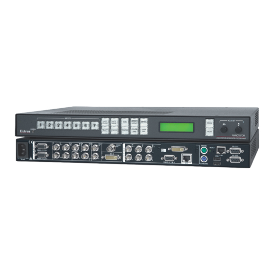
Annotator Optional Output Board Installation Notes
The Extron Annotator has a series of optional output boards:
Scan converter, HD-SDI, and DVI-D. The boards mount
in the optional output slot, above the RGB and MTP ports,
at the rear of the Annotator. For full operating details of the
Annotator refer to the Annotator User's Manual, available
at www.extron.com.
To install an output board in the Annotator unit,
1. Turn off the Annotator, and remove the power cord.
Repeat for all connected devices.
2. Remove eight cover securing screws from the top, and
three from each side. Slide the top cover off.
Retain the fourteen screws.
3a. At the rear optional output slot, remove the two
securing screws
Lift the plate away. Retain the screws.
1
N
Re-use the screws to secure the new output board in place. Retain the blank plate.
3b. If a board is already installed in the output slot, remove any cables and the two outer screws
Then remove a third retaining screw that secures it to the post on the Annotator motherboard.
Carefully lift the board away from the socket.
4. Remove the new board from its box and anti-ESD bag, holding the board by the front frame.
5. Turn the board over and insert the supplied connector pins into the sockets on
the board.
6. Turn the board over. With the pin connectors now facing down, carefully align
the pins with the appropriate sockets on the motherboard. Push the board
firmly down into the sockets.
7. Secure the board to the frame with the two retaining screws
the post on the motherboard using either the original or the supplied screw.
8. Replace the cover, securing it with the fourteen screws removed in step 2.
9. Reconnect any input and output devices including connection to the new board.
10. Connect any control devices.
11. Power on the Annotator and all the connected devices.
a
from either side of the blank plate.
C
VID
LO-
RES
R-Y/
Y/
OUT
R
G
RGB/R-Y,Y,B-Y
MTP
1
Y
B-Y/
B
(Continued on reverse side)
C
VID
LO-
RES
R-Y/
Y/
OUT
R
G
HDSDI
OUT
DVI-D
OUT
a
and to
Y
B-Y/
B
a
.
Advertisement

Related Manuals for Extron electronics Annotator


Summary of Contents for Extron electronics Annotator
- Page 1 3b. If a board is already installed in the output slot, remove any cables and the two outer screws Then remove a third retaining screw that secures it to the post on the Annotator motherboard. Carefully lift the board away from the socket.
- Page 2 Annotator Output Board Installation Notes, cont’d Configuring the boards using the front panel menu system To configure the HD-SDI and DVI-D boards using the menu system, refer to the Annotator User’s Manual available at www.extron.com. The Annotator has a separate front panel menu for configuring the scan converter board.
Need help?
Do you have a question about the Annotator and is the answer not in the manual?
Questions and answers