Rohde & Schwarz R&S SMW200A User Manual
Vector signal generator
Hide thumbs
Also See for R&S SMW200A:
- User manual (1312 pages) ,
- User manual (37 pages) ,
- User manual (1484 pages)
Table of Contents
Advertisement
Quick Links
Advertisement
Chapters
Table of Contents

Subscribe to Our Youtube Channel
Related Manuals for Rohde & Schwarz R&S SMW200A


Summary of Contents for Rohde & Schwarz R&S SMW200A
- Page 1 ® R&S SMW200A Vector Signal Generator User Manual (;ÙÐP2) 1175663202 Version 30...
- Page 2 ® This document describes the R&S SMW200A, stock no. 1412.0000.02 and its options: ● ® R&S SMW-B9/-B10/-B10F ● ® R&S SMW-B13/-B13T/-B13XT ● ® R&S SMW-B20 ● R&S ® SMW-B22 ● ® R&S SMW-B81/-B82/-B83/-B84 ● ® R&S SMW-B90 ● R&S ® SMW-B93 ●...
-
Page 3: Table Of Contents
® Contents R&S SMW200A Contents 1 Safety and Regulatory Information............ 19 Safety Instructions......................19 Labels on R&S SMW....................21 Warning Messages in the Documentation..............22 Korea Certification Class B..................22 2 Welcome....................23 Key Features........................23 Documentation Overview................... 23 2.2.1 Getting Started Manual....................24 2.2.2 User Manuals and Help....................24 2.2.3... - Page 4 ® Contents R&S SMW200A 3.1.12 Connecting to HS DIG I/Q.....................35 3.1.13 Switching On or Off....................... 36 Instrument Tour......................37 3.2.1 Front Panel Tour......................37 3.2.2 Rear Panel Tour......................44 Trying Out the Instrument..................52 3.3.1 Generating an Unmodulated Carrier................53 3.3.2 Generating a Digitally Modulated Signal...............
- Page 5 ® Contents R&S SMW200A 4.2.2 Using the System Configuration Capabilities...............111 Overview of the Input and Output Signals and Interfaces........113 4.3.1 Physical Location of the Input and Output Interfaces..........114 4.3.2 Overview of the Baseband Signal Sources..............116 4.3.3 Overview of the Baseband and RF Output Signals............. 118 4.3.4 Supported Digital Interfaces Depending on the System Configuration.......
- Page 6 ® Contents R&S SMW200A 4.9.11 How to Connect an R&S EX-IQ-BOX................214 5 Configuring the Internal Baseband Source........216 Overview of the Signal Generation Modes............. 216 Standard or Wideband Baseband Generator............217 Accessing the Functions in the Baseband Domain..........219 Generating Signals According to Digital Standards..........220 Common Functions and Settings in the Baseband Domain.........
- Page 7 ® Contents R&S SMW200A 5.10.5 Reference to Triggering of Multi-Segment Waveforms..........378 5.11 Generating Multi-Carrier Signals................381 5.11.1 Required Options......................382 5.11.2 About the Multi-Carrier Waveforms................382 5.11.3 Multi-Carrier Settings....................384 5.11.4 How to Use the Multi-Carrier Function................ 396 5.12 Generating Multi-Carrier Continuous Wave Signal..........398 5.12.1 Required Options......................
- Page 8 ® Contents R&S SMW200A 6.4.1 Required Options......................440 6.4.2 About the Linear I/Q Impairments................440 6.4.3 Analog and Digital Impairments Settings..............442 6.4.4 How to Optimize the Carrier Leakage and Sidebands Suppression......446 Frequency Response Correction................447 Applying Digital Predistortion................. 447 7 Applying I/Q Vector Modulation............448 Required Options......................
- Page 9 ® Contents R&S SMW200A 8.7.2 About Sweep Mode.....................500 8.7.3 About List Mode......................504 8.7.4 Significant Parameters and Functions................ 505 8.7.5 Sweep Mode Settings....................508 8.7.6 List Mode Settings.......................517 8.7.7 List Editor........................524 8.7.8 How to Generate a Signal in List or Sweep Mode............527 Analog Modulations....................529 8.8.1 Required Options......................
- Page 10 ® Contents R&S SMW200A 10.2 Generating Phase-Coherent Signals...............639 10.3 Generating Time-Aligned Baseband Signals............640 10.3.1 Connecting Multiple Instruments in Primary-Secondary Instrument Mode....640 10.3.2 Triggering Several Instruments with a Common Trigger Signal........648 10.4 Generating Phase-Coherent Synchronous and Aligned Signals......650 10.4.1 Required Options......................
- Page 11 ® Contents R&S SMW200A 11.8.3 How to Display All Saved Files................... 694 11.8.4 How to Map a Network Folder..................694 11.9 How to Transfer Files from and to the Instrument..........696 11.9.1 Removing File System Protection................697 11.9.2 Accessing the File System of the R&S SMW via ftp........... 698 11.9.3 Accessing the R&S SMW File System via SMB (Samba)...........699 11.9.4...
- Page 12 ® Contents R&S SMW200A 12.4.2 Using the License Server.................... 746 12.4.3 How to Move a Portable License................750 12.5 Managing Extensions....................751 12.5.1 Manage Extension Settings..................751 12.5.2 How to Install or Deinstall an Extension..............752 12.6 Using the Security Settings..................752 12.6.1 Protection Level Settings....................
- Page 13 ® Contents R&S SMW200A 13.5 LXI Settings....................... 795 13.5.1 LXI Status Settings......................795 13.5.2 LXI Browser Settings....................797 13.6 Connecting the Instrument to the Network (LAN)..........803 13.6.1 How To Enable Access via LAN..................803 13.6.2 How To Activate LAN Services..................803 13.6.3 How To Connect to LAN....................804 13.6.4 How to Assign the IP Address..................804 13.6.5...
- Page 14 ® Contents R&S SMW200A 13.10.3 Remote Control States....................840 14 Remote Control Commands..............841 14.1 Conventions Used in SCPI Command Descriptions..........841 14.2 Backward Compatibility with Other Rohde & Schwarz Signal Generators..842 14.3 SCPI Command Aliases for Advanced Mode with Multiple Entities....842 14.4 Programming Examples...................
- Page 15 ® Contents R&S SMW200A 14.19.2 SOURce:BBIN Subsystem..................954 14.19.3 Analog Modulation Subsystems..................964 14.19.4 SOURce:BB Subsystem..................... 984 14.19.5 SOURce:CORRection Subsystem................1114 14.19.6 SOURce:FREQuency Subsystem................1124 14.19.7 SOURce:FREQuency:CONVerter Subsystem............1133 14.19.8 SOURce:INPut Subsystem..................1135 14.19.9 SOURce:IQ Subsystem.....................1136 14.19.10 SOURce:IQ:OUTPut Subsystem................1139 14.19.11 SOURce:LFOutput Subsystem..................1152 14.19.12 SOURce:LIST Subsystem..................1164 14.19.13 SOURce:NOISe Subsystem..................1179 14.19.14...
- Page 16 ® Contents R&S SMW200A 15.7.1 Hardware Configuration Settings................1263 15.7.2 Versions/Options Settings..................1264 15.7.3 How to Query Instrument Configuration..............1266 15.7.4 How to Request the Data Sheet................1267 15.8 Collecting Information for Technical Support............1267 15.9 Contacting Customer Support................1269 16 Transporting..................1270 17 Maintenance, Storage and Disposal..........1271 17.1 Cleaning........................
- Page 17 ® Contents R&S SMW200A Additional Basics on Remote Control..............1314 D.1.1 Messages........................1314 D.1.2 LAN Interface Messages...................1315 D.1.3 SCPI Command Structure..................1315 D.1.4 Command Sequence and Synchronization...............1323 D.1.5 Status Reporting System..................1327 D.1.6 General Programming Recommendations..............1335 Telnet program examples..................1335 Extensions for User Files..................1340 E Hardware Interfaces.................1343 GPIB-Bus Interface....................
- Page 18 ® Contents R&S SMW200A User Manual 1175.6632.02 ─ 30...
-
Page 19: Safety And Regulatory Information
® Safety and Regulatory Information R&S SMW200A Safety Instructions 1 Safety and Regulatory Information The product documentation helps you use the product safely and efficiently. Follow the instructions provided here and in the Chapter 1.1, "Safety Instructions", on page 19. Intended use The product is intended for the development, production and verification of electronic components and devices in industrial, administrative, and laboratory environments. - Page 20 ® Safety and Regulatory Information R&S SMW200A Safety Instructions move or carry the product. Do not lift by the accessories mounted on the product. Accessories are not designed to carry the weight of the product. To move the product safely, you can use lifting or transporting equipment such as lift trucks and forklifts.
-
Page 21: Labels On R&S Smw
® Safety and Regulatory Information R&S SMW200A Labels on R&S SMW ● Only use the power cable delivered with the product. It complies with country-spe- cific safety requirements. Only insert the plug into an outlet with protective conduc- tor terminal. ●... -
Page 22: Warning Messages In The Documentation
® Safety and Regulatory Information R&S SMW200A Korea Certification Class B ● Identification of the product, see the serial number on the rear panel. Table 1-1: Labels regarding R&S SMW and environment safety Labeling in line with EN 50419 for disposal of electrical and electronic equipment after the prod- uct has come to the end of its service life. -
Page 23: Welcome
® Welcome R&S SMW200A Documentation Overview 2 Welcome The R&S SMW is a new high-performance signal generator developed to meet demanding customer requirements. Offering excellent signal characteristics, wide sig- nal bandwidth and straightforward and intuitive operation, the signal generator makes signal generation fast and easy. -
Page 24: Getting Started Manual
® Welcome R&S SMW200A Documentation Overview 2.2.1 Getting Started Manual Introduces the R&S SMW and describes how to set up and start working with the prod- uct. Includes basic operations, typical measurement examples, and general informa- tion, e.g. safety instructions, etc. A printed version is delivered with the instrument. 2.2.2 User Manuals and Help Separate manuals for the base unit and the software options are provided for down- load:... -
Page 25: Printed Safety Instructions
® Welcome R&S SMW200A Scope and Content 2.2.6 Printed Safety Instructions Provides safety information in many languages. The printed document is delivered with the product. 2.2.7 Data Sheets and Brochures The data sheet contains the technical specifications of the R&S SMW. It also lists the options and their order numbers and optional accessories. - Page 26 ® Welcome R&S SMW200A Scope and Content The values ranges in the remote control commands correspond to a Standard base- band instrument. Settings and descriptions related to RF hardware versions To improve the signal performance of the R&S SMW, several hardware components in the RF domain have been replaced.
-
Page 27: Getting Started
® Getting Started R&S SMW200A Preparing for Use 3 Getting Started 3.1 Preparing for Use Here, you can find basic information about setting up the instrument for the first time. 3.1.1 Lifting and Carrying ► WARNING! The R&S SMW can be heavy, e.g., if fully equipped. Use a lifting equipment, see also "Lifting and carrying the product"... -
Page 28: Setting Up The R&S Smw
® Getting Started R&S SMW200A Preparing for Use – Environments that are directly connected to a low-voltage supply network that supplies residential buildings ● Class A equipment is intended for use in industrial environments. It can cause radio disturbances in residential environments due to possible conducted and radi- ated disturbances. - Page 29 ® Getting Started R&S SMW200A Preparing for Use Left = Stacked correctly, same dimensions Middle = Stacked correctly, different dimensions Right = Stacked incorrectly, too many products 4. NOTICE! Overheating can damage the product. Prevent overheating as follows: ● Keep a minimum distance of 10 cm between the fan openings of the product and any object in the vicinity.
-
Page 30: Considerations For Test Setup
® Getting Started R&S SMW200A Preparing for Use 4. Tighten all screws at the rack brackets with a tightening torque of 1.2 Nm to secure the R&S SMW in the rack. To unmount the R&S SMW from a rack 1. Loosen the screws at the rack brackets. 2. -
Page 31: Connecting To Power
® Getting Started R&S SMW200A Preparing for Use How to: Chapter 3.1.12, "Connecting to HS DIG I/Q", on page 35 Signal input and output levels Information on signal levels is provided in the data sheet. Keep the signal levels within the specified ranges to avoid damage to the R&S SMW and connected devices. -
Page 32: Connecting Usb Devices
® Getting Started R&S SMW200A Preparing for Use ► Connect the LAN socket via an RJ-45 cable to the LAN. By default, the R&S SMW is configured to use DHCP (dynamic host configuration pro- tocol) and no static IP address is configured. If switched on and connected to the LAN, the R&S SMW displays the address informa- tion on the screen. -
Page 33: Connecting To Rf A/Rf B
® Getting Started R&S SMW200A Preparing for Use To connect power sensors You can connect power sensors of the R&S NRP families to any of the USB connec- tors. Chapter 8.9.4, "Using Power Sensors", on page 581. 3.1.9 Connecting to RF A/RF B The connector is located on the front panel. - Page 34 ® Getting Started R&S SMW200A Preparing for Use 2. NOTICE! Risk of instrument damage and connector damage. Excessive tightening can damage the cables and the connectors. However, if you do not tighten the con- nectors enough, the measurement results can be inaccurate. To connect the cable with the connector, proceed as follows: a) Carefully align the connector of the cable and the connector along a common axis.
-
Page 35: Connecting To Lo In/Out
® Getting Started R&S SMW200A Preparing for Use 3.1.10 Connecting to LO In/Out "LO In/Out" connectors are Subminiature Version A (SMA) connectors. The connector is located on the rear panel. Follow the instructions in "To connect to screwable connectors" on page 33. See also Chapter 8.6, "Local Oscillator Coupling",... -
Page 36: Switching On Or Off
® Getting Started R&S SMW200A Preparing for Use To connect to HS DIG I/Q interface 1. For connection, use the QSFP+ cable R&S DIGIQ-HS. "Cable selection and electromagnetic interference (EMI)" on page 30. 2. Hold the QSFP+ plug of the cable by its panes. 3. -
Page 37: Instrument Tour
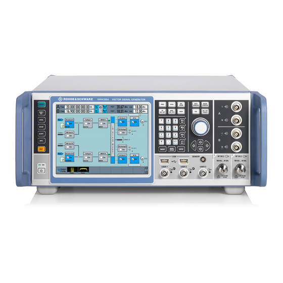
® Getting Started R&S SMW200A Instrument Tour The LED changes to green. The R&S SMW boots. When starting for the first time, the R&S SMW starts with the default settings. When restarting the instrument, the settings depend on the instrument configura- tion before shut-down. - Page 38 ® Getting Started R&S SMW200A Instrument Tour The user interface can be displayed on a remote PC station used to manually remote control the instrument. Figure 3-2: R&S SMW front panel controls and connectors Utility Keys, page 39 Touchscreen, page 38 Function Keys, page 40 Keypad, page 41 Navigation Controls, page 41...
- Page 39 ® Getting Started R&S SMW200A Instrument Tour Figure 3-3: Touchscreen elements 1 = Status bar (frequency and level display) 2 = Block diagram 3 = Taskbar/softkey bar Any user interface elements that react to a click by a mouse pointer also react to a tap on the screen, and vice versa.
- Page 40 ® Getting Started R&S SMW200A Instrument Tour For more information, refer to Chapter 12, "General Instrument Functions", on page 709. Table 3-3: Utility keys Utility key Assigned functions [PRESET] Sets the instrument to a defined state [SAVE/RCL] Saves and loads instrument setting Accesses the file manager [LOCAL] Switches from remote control to local (manual) control...
- Page 41 ® Getting Started R&S SMW200A Instrument Tour Status is displayed in the "Status bar". The key switches off all RF signals/modula- tions; press the key again to restore the last active status. Keypad The keypad is used to enter alphanumeric parameters, including the corresponding units.
- Page 42 ® Getting Started R&S SMW200A Instrument Tour ● Acts like the [Enter] key, when it is pressed. Navigation Keys The navigation keys can be used alternatively to the rotary knob to navigate through dialog boxes, diagrams, or tables. Table 3-6: Navigation keys Type of key Description [Up/Down] key...
- Page 43 ® Getting Started R&S SMW200A Instrument Tour Use the connectors for connections as follows: ● I/Q connectors: Direct (single-ended) or positive differential input of analog I/Q sig- nals ● I/Q Bar connectors: Negative differential input of analog I/Q signals How to: ●...
-
Page 44: Rear Panel Tour
® Getting Started R&S SMW200A Instrument Tour The connector type depends on the maximum frequency f , see table below. Table 3-9: RF connector types of the frequency options Installed RF frequency Connector type Frequency range option ≤ 7.5 GHz RF A: R&S SMW-B1003/- N female B1006/-B1007... - Page 45 ® Getting Started R&S SMW200A Instrument Tour Figure 3-4: R&S SMW rear panel controls and connectors (R&S SMW-B10/-B13T)* * = R&S SMW equipped with standard baseband generator Connectors for rack use, external reference signal, external frequency control, local oscillator and remote control, page 45 System drive, power switch, power supply, monitor, LAN and USB connectors, page 46 Instrument boards R&S SMW-B10/-B13T/-B14 (standard baseband), page...
- Page 46 ® Getting Started R&S SMW200A Instrument Tour = Connectors for rack use: I/Q, page 47 RF A/RF B, page 47 2, 3 = REF IN/REF OUT, page 47 INST TRIG x, page 50 USER x, page 48 EFC, page 48 = Serial number (six digits in the string 1412.0000.02-<serial number>-<checksum>) LO IN/LO OUT, page 48 IEC 625/IEEE 488, page 48...
- Page 47 ® Getting Started R&S SMW200A Instrument Tour BBMM Figure 3-8: Instrument boards: R&S SMW-B9/-B13XT/-B15 (wideband baseband) 1, 6, 13, 15 = DIG I/Q, page 50 2, 7, 12, 14 = HS DIG I/Q, page 51 3, 8 ADV DATA/CTRL, page 51 4, 9 T/M/C, page 49 5, 16...
- Page 48 ® Getting Started R&S SMW200A Instrument Tour SMA connectors for 1 GHz reference signals. The external reference is used for both paths. How to: Chapter 3.1.11, "Connecting to REF IN/REF OUT", on page 35 USER x BNC multipurpose connectors for defining input signals and output signals. Table 3-10 lists the signals assigned to the USER x connectors in the default instru- ment state.
- Page 49 ® Getting Started R&S SMW200A Instrument Tour For security reasons, the hard disk is bound to the specific R&S SMW. You can remove it from the instrument, but you cannot use it in other instruments. See also "Removing the system drive from the R&S SMW" on page 679.
- Page 50 ® Getting Started R&S SMW200A Instrument Tour Table 3-12: Default configuration of the T/M/C connectors (wideband baseband) T/M/C connector Direction Default assigned signal Output Symbol clock Input External serial data A dedicated LED indicates the connector status: ● green: an input connector ●...
- Page 51 ® Getting Started R&S SMW200A Instrument Tour LF OUT x Option: R&S SMW-B13/-B13T Output for internal LF generator signal. Note: The output of the internal LF signal and the analog I/Q signal use the same physical connectors. Therefore, consider that you cannot output both signals simulta- neously.
-
Page 52: Trying Out The Instrument
® Getting Started R&S SMW200A Trying Out the Instrument The interfaces require the options listed in Table 3-14. For more information, see data sheet. Table 3-14: Overview of HS DIG I/Q interfaces and required options Location of the interface Designation Required option CODER board CODER 1/2 In... -
Page 53: Generating An Unmodulated Carrier
® Getting Started R&S SMW200A Trying Out the Instrument ● Enabling and Configuring a Marker Signal..............63 ● Routing a Baseband Signal to the Outputs............. 64 ● Verifying the Generated Signal................69 ● Saving and Recalling Settings................71 ● Generating an EUTRA/LTE Signal................73 ●... - Page 54 ® Getting Started R&S SMW200A Trying Out the Instrument Figure 3-9: Block diagram: Generating an unmodulated signal Tip: Alternative way to access the instrument functions. To fulfill the same task, you can use other hot spots in the block diagram, the provided functions under the "RF" block or the function front panel keys.
-
Page 55: Generating A Digitally Modulated Signal
® Getting Started R&S SMW200A Trying Out the Instrument To enable signal generation, enable the "RF On". ● Use the [FREQ], [LEVEL], and [RF ON/OFF] key on the front panel. See also Chapter 3.5, "Instrument Control", on page 90. The 1.95 GHz signal is output at the RF A connector at the front panel of the R&S SMW. - Page 56 ® Getting Started R&S SMW200A Trying Out the Instrument The "Custom Digital Modulation" dialog opens. 2. In the "Custom Digital Modulation" dialog, select "General > Set acc to standard > WCDMA-3GPP". 3. Select "General > State > On" to enable signal generation. 4.
-
Page 57: Triggering The Instrument With An External Signal
® Getting Started R&S SMW200A Trying Out the Instrument Figure 3-11: Display of the used modulation type The instrument activates automatically "I/Q Mod A", uses the internal trigger and clock signals, and generates a WCDMA-3GPP signal, modulated with a QPSK 45° offset modulation. - Page 58 ® Getting Started R&S SMW200A Trying Out the Instrument generation start time. A defined trigger event starts signal generation, e.g. when trig- gering the instrument internally or externally from the DUT. This example illustrates the general principle of external triggering and extends the configuration performed in Chapter 3.3.2, "Generating a Digitally Modulated Signal",...
- Page 59 ® Getting Started R&S SMW200A Trying Out the Instrument The instrument uses its internal trigger and clock signals, and the default mapping of the marker signals to the connectors. 2. To access the related connector settings, perform one of the following: ●...
- Page 60 ® Getting Started R&S SMW200A Trying Out the Instrument Figure 3-13: Signal mapping to the global connectors The "Global Connectors" dialog displays the current connectors configuration. The settings are configurable, but in this example we use the default mapping. 3. Alternatively, select "Block Diagram > Baseband > Misc > Custom Digital Mod", select the "...
- Page 61 ® Getting Started R&S SMW200A Trying Out the Instrument To reconfigure the trigger settings We assume that the instrument is configured as described in Chapter 3.3.2, "Generat- ing a Digitally Modulated Signal", on page 55 and the default connector mapping is maintained (see Figure 3-13).
- Page 62 ® Getting Started R&S SMW200A Trying Out the Instrument Reference REF IN REF OUT (Rear Panel) USER 3 RF A INPUT TRIGGER INPUT Signal Global Trigger 1 External Trigger Source Figure 3-14: Simplified representation of a test setup** ** = The figure depicts the cabling as a general principle; a particular test setup does not require all con- nections at the same time.
-
Page 63: Enabling And Configuring A Marker Signal
® Getting Started R&S SMW200A Trying Out the Instrument 2. Use suitable cables to connect the RF A/B REF OUT connectors of the R&S SMW to the signal analyzer or the DUT. Upon the receiving of an external trigger event, the R&S SMW starts the signal generation and then generates a continuous signal. -
Page 64: Routing A Baseband Signal To The Outputs
® Getting Started R&S SMW200A Trying Out the Instrument In this example, we use the global USER connectors. Alternatively, you can achieve the same configuration goal with the local T/M/C connectors. ® This test setup requires one oscilloscope, like the R&S RTO, as additional equipment. - Page 65 ® Getting Started R&S SMW200A Trying Out the Instrument described in Chapter 3.3.3, "Triggering the Instrument with an External Signal", on page 57. The minimum requirement for the instrument in this example is an R&S SMW equipped with the options 2xR&S SMW-B10, R&S SMW-B13T, and R&S SMW-B1003/-B2003. To configure a composed baseband signal 1.
- Page 66 ® Getting Started R&S SMW200A Trying Out the Instrument 3. In the block diagram, select "Baseband B > Misc > Custom Digital Mod...", select "Set acc. to standard > 3GPP FDD" and enable "Custom Digital Modulation > State > On". 4.
- Page 67 ® Getting Started R&S SMW200A Trying Out the Instrument The symbols in the block diagram confirm that the signals are added weighted with a frequency offset on both paths and a path gain on path B. Figure 3-16: Block diagram: Generating a composed signal (stream A) To enable simultaneous signal generation in both basebands, the R&S SMW cou- ples the trigger settings in the available basebands.
- Page 68 ® Getting Started R&S SMW200A Trying Out the Instrument Stream A is routed to all the available output connectors: the analog RF A and I/Q ("I/Q OUT 1") connectors, and the digital I/Q output connectors DIG I/Q ("BBMM1"). 2. To reconfigure the mapping, tap a matrix entry, for example disable the output of stream A on the BBMM 1 interface.
-
Page 69: Verifying The Generated Signal
® Getting Started R&S SMW200A Trying Out the Instrument To learn more and to explore the whole range of routing capability, refer to Chapter 4, "Signal Routing and System Configuration", on page 106. 3.3.6 Verifying the Generated Signal It is often useful to check the spectra of the configured signals, before you enable the RF output of the instrument. - Page 70 ® Getting Started R&S SMW200A Trying Out the Instrument A new thumbnail (minimized view) indicating the active diagram appears in the "Taskbar". 4. Press the thumbnail graphic. The graphic enlarges and the diagram is displayed in a normal size. The "Power Spectrum" displays two signals, both 3GPP FDD signals are frequency shifted and the right one is also attenuated.
-
Page 71: Saving And Recalling Settings
® Getting Started R&S SMW200A Trying Out the Instrument 6. In the "Power Spectrum" dialog, select "Configure" to return to the "Graphics Con- figuration" dialog. Close the "Graphics Configuration" dialog. This action has no effect on the configured graphics but on the dialog itself. The block diagram displays the current signal routing. - Page 72 ® Getting Started R&S SMW200A Trying Out the Instrument 3. Tap the "Save" button. The file MyTestSignal.savrcltxt is saved in the default directory /var/user. To load saved instrument settings You can restore the settings to the instrument at any time using the settings file. 1.
-
Page 73: Generating An Eutra/Lte Signal
® Getting Started R&S SMW200A Trying Out the Instrument Try out the following: ● Tap and hold on an empty space in the block diagram to access the context-sensi- tive menu. ● Select "Mark all parameters changed from preset". ● All changed parameters are highlighted. - Page 74 ® Getting Started R&S SMW200A Trying Out the Instrument EUTRA/LTE to introduce the way you can access and interact with the instrument and experience the advantages provided by the additional options. The minimum requirement for R&S SMW in this example is a base unit equipped with the additional option R&S SMW-K55 EUTRA/LTE.
- Page 75 ® Getting Started R&S SMW200A Trying Out the Instrument The test models is a function for quick selection and settings adjustment according to one of the various EUTRA test models (E-TM). A standard "File Select" function enables you to select form files with predefined settings.
-
Page 76: Enabling Mimo Configuration
® Getting Started R&S SMW200A Trying Out the Instrument Select "RF A > On". The instrument generates an EUTRA/LTE test signal with the selected channel bandwidth, frequency, and level. With these first steps, you have gained an impression of the provided functionality. For a comprehensive description of the full range of capabilities, refer to the user man- ual "EUTRA/LTE Digital Standard for R&S SMW200A". - Page 77 ® Getting Started R&S SMW200A Trying Out the Instrument The instrument in this example is a R&S SMW equipped with two signal paths: ● 2 options standard baseband generator R&S SMW-B10 and one R&S SMW-B13T ● 2 options fading simulator R&S SMW-B14 and one option fading MIMO R&S SMW- ●...
- Page 78 ® Getting Started R&S SMW200A Trying Out the Instrument The "System Configuration > Fading/Baseband Configuration" dialog displays the current signal routing. The instrument works in the default "Standard" mode. Figure 3-17: System Configuration in the default Standard Mode 1 = Standard or advanced mode; the last is required for configuration of complex LxMxN MIMO scenar- 2 = Simplified preview diagram with a description of the common application for the particular configura- tion 2.
- Page 79 ® Getting Started R&S SMW200A Trying Out the Instrument Figure 3-18: System Configuration in the Advanced Mode (1x2x2 configuration) 1 = Advanced mode, required for configuration of complex LxMxN MIMO scenarios 2 = Simplified preview diagram of the particular configuration 3 = Current signal routing;...
- Page 80 ® Getting Started R&S SMW200A Trying Out the Instrument In coupled baseband source mode, the R&S SMW takes over the baseband signal configuration. The instrument adjusts the settings in the basebands automatically, for example the mapping of the transmitting antennas to the basebands. 2.
-
Page 81: System Overview
® Getting Started R&S SMW200A System Overview 3.4 System Overview This section helps you to get familiar with the R&S SMW. It provides an introduction to the general concept of the instrument with a sample of the possible application fields. This section also introduces the main blocks in the signal generation flow. - Page 82 ® Getting Started R&S SMW200A System Overview The first one shows the default instrument state and the second one - an advanced configuration with more abstract representation. – In this "classic" representation, the block diagram displays all blocks for that the required hardware and software options are fitted.
- Page 83 ® Getting Started R&S SMW200A System Overview The cross-reference between the installed options and the displayed settings Table 3-15 is an excerpt of the available options and lists only the options required to display a functional block in the block diagram. The information assumes R&S SMW equipped with standard baseband generator R&S SMW-B10 and R&S SMW-B13T.
- Page 84 ® Getting Started R&S SMW200A System Overview ● The signal routing (in the standard "classic" mode of a standard baseband genera- tor) Signals from the baseband generators can be routed between the available paths, and added (possibly with frequency, phase and power offsets). 3.4.1.3 Digital Baseband Input and Output ("BB Input", "I/Q Digital"...
- Page 85 ® Getting Started R&S SMW200A System Overview ● The option R&S SMW-K71 comprises the 3GPP dynamic fading configurations moving propagation and birth-death propagation, and the fine delay fading configu- rations offering enhanced delay resolution ● The option R&S SMW-K72 extends the statistic functions and is required for addi- tional fading profiles and some of the predefined test scenarios ●...
-
Page 86: Applications Examples Of The R&S Smw
® Getting Started R&S SMW200A System Overview 3.4.1.9 RF and Analog Modulations ("RF" Blocks) The "RF" block represents the RF settings of the instrument. This block is the access point to: ● RF frequency and level settings, the reference frequency, local oscillator, user cor- rection, etc. - Page 87 ® Getting Started R&S SMW200A System Overview 3.4.2.2 Receive Diversity Test (SIMO Scenario) The block diagram in this example depicts the generation of a test signal using one internal baseband generator ("Baseband A") and distributing the signal to both RF out- puts.
- Page 88 ® Getting Started R&S SMW200A System Overview 3.4.2.3 Generation of Signals for Testing of WCDMA Handover (Two Cells) The block diagram in this example depicts the generation of a test signal using both internal baseband generators and both RF outputs, for example for handover tests. The R&S SMW acts as two independent generators in one instrument.
- Page 89 ® Getting Started R&S SMW200A System Overview 3.4.2.5 Generation of an LTE Test Signal with Carrier Aggregation and 2x2 MIMO each Component Carrier The block diagram in this example depicts the generation of an EUTRA/LTE test signal with two component carriers (intra-band carrier aggregation) and 2x2 MIMO fading each, for example for UE tests.
-
Page 90: Instrument Control
® Getting Started R&S SMW200A Instrument Control 3.5 Instrument Control This chapter provides an overview on how to work with the R&S SMW. It covers the following topics: ● Possible Ways to Operate the Instrument...............90 ● Means of Manual Interaction...................91 ●... -
Page 91: Means Of Manual Interaction
® Getting Started R&S SMW200A Instrument Control ● Remote operation from a computer: Remote monitoring and control of the instrument from a connected computer is based on the common cross-platform technology VNC (Virtual Network Comput- ing). On the remote computer, any standard web browser (supporting Java) or a dedicated VNC client (like Ultr@VNC) can be used. -
Page 92: Understanding The Display Information
® Getting Started R&S SMW200A Instrument Control 3.5.3 Understanding the Display Information The block diagram of the R&S SMW displays all main settings and generator states, divided into three main operation areas. Figure 3-21: Block diagram 1 = Status bar 2 = Block diagram 3 = Taskbar/softkey bar ●... - Page 93 ® Getting Started R&S SMW200A Instrument Control 1 = Frequency display 2 = Status buttons 3 = Level display The status buttons indicate key parameters that are set for the output signal. Most of the status buttons are virtual keys you can use to open a corresponding menu or dia- log.
- Page 94 ® Getting Started R&S SMW200A Instrument Control Legend Item Description Connector icons Represent the interfaces for signal input and output: ● Digital I/Q signal connector input (1) ● Analog I/Q signal connector input (9) ● RF signal connector output (12) Icons vary depending on the frequency.
- Page 95 ® Getting Started R&S SMW200A Instrument Control Figure 3-23: Taskbar fully assigned 1 = System configuration 2 = Remote control connections 3 = R&S NRP power sensors 4 = Graphics 5 = Dialogs 6 = Diagram / more System Config Provides access to general system configurations like setup, display, or remote.
- Page 96 ® Getting Started R&S SMW200A Instrument Control The "Info line" shows brief status information and error messages. It appears when an event generates a message. If selected, the R&S SMW shows information on static errors and the error history. ● Key parameters indicated in tab labels Most dialogs are divided into tabs with logically grouped parameters.
-
Page 97: Accessing The Functionality
® Getting Started R&S SMW200A Instrument Control 3.5.4 Accessing the Functionality All functionalities are provided in dialog boxes as known from computer programs. You can control the instrument intuitively with the touchscreen. This section provides an overview of the accessing methods. The instrument's functions and settings can be accessed by selecting one of the follow- ing elements: ●... -
Page 98: Entering Data
® Getting Started R&S SMW200A Instrument Control To close a dialog box To close a dialog box, you have the same controls as you know from computers or devices with touchscreen. ► Perform one of the following actions: ● Tap the "Close" icon in the upper right corner. ●... - Page 99 ® Getting Started R&S SMW200A Instrument Control To abort the entry ► Press the [ESC] key. The dialog box closes without changing the settings. 3.5.5.1 Entering Numeric Parameters To enter values with the on-screen keypad For numeric settings, the instrument displays the numeric keypad. The units specified correspond to the units of the parameter.
-
Page 100: Getting Information And Help
® Getting Started R&S SMW200A Instrument Control "Redo" restores a previously undone action. 3.5.6 Getting Information and Help In some dialog boxes, graphics are included to explain the way a setting works. For further information, you can use the following sources: ●... - Page 101 ® Getting Started R&S SMW200A Instrument Control Contents of the help dialog box The help dialog box covers two main areas: ● "Contents" - contains a table of help contents ● "Topic" - contains a specific help topic The help system also provides an "Index" and a "Find" area, and "Zoom" functions that are accessed via the corresponding buttons.
- Page 102 ® Getting Started R&S SMW200A Instrument Control 6. To maximize the "Topics" area, tap the "Hide Contents Tree" button to hide the con- tents tree. Using the index 1. Select the "Index" button. 2. Enter the first characters of the topic you are interested in. The entries starting with these characters are displayed.
- Page 103 ® Getting Started R&S SMW200A Instrument Control 4. Tap on a tutorial from the list and confirm with "Select". If the file contains a description, it is displayed. User Manual 1175.6632.02 ─ 30...
- Page 104 ® Getting Started R&S SMW200A Instrument Control 5. Use the default mode, that is "Execution Mode > Interactive". 6. Tap on the "Start" button. 7. Observe the information displayed in the "Info" line (bottom of the display). 1 = Information on the performed action 2 = Progress bar 3 = "Next Step": confirms the execution of the step 4 = "Stop": terminates the tutorial...
-
Page 105: Remote Control
® Getting Started R&S SMW200A Instrument Control See also: ● Chapter F, "Available Tutorial Files", on page 1345 ● The application sheet "RS_SMW_CreatingTutorials_AppSheet", available for download from the R&S website, on the R&S SMW product page. 3.5.7 Remote Control In addition to working with the R&S SMW interactively, located directly at the instru- ment, it is also possible to operate and control it from a remote PC. -
Page 106: Signal Routing And System Configuration
® Signal Routing and System Configuration R&S SMW200A How the System Configuration Function Supports You in Your Task 4 Signal Routing and System Configuration The R&S SMW provides multiple routing possibilities and simplifies the definition of versatile MIMO configurations. Provided the instrument is equipped with the required options, R&S SMW can: ●... - Page 107 ® Signal Routing and System Configuration R&S SMW200A How the System Configuration Function Supports You in Your Task ment to evaluate type and number of additional instruments, that are required in the current test setup. General workflow for finding out the suitable system configuration for a current use case The general workflow comprises the main phases listed bellow.
-
Page 108: From A Test Scenario To The Required System Configuration
® Signal Routing and System Configuration R&S SMW200A How the System Configuration Function Supports You in Your Task 4.1.2 From a Test Scenario to the Required System Configuration The information in Table 4-1 provides a cross-reference between a test scenario and the required configuration. - Page 109 ® Signal Routing and System Configuration R&S SMW200A How the System Configuration Function Supports You in Your Task Test scenario Short description/application "Fading and "Baseband Required output sig- Required addi- Baseband Source nals per instrument tional instru- Config" "configura- ments tion ●...
-
Page 110: Possible Ways To Configure The Signal Flow
® Signal Routing and System Configuration R&S SMW200A Possible Ways to Configure the Signal Flow Table 4-2: Example of scenarios for signaling tests Test scenario Short description/application "Fading and "Baseband Required Input/ Required Baseband Source output signals per additional Config" "configura- instrument instruments... -
Page 111: Using The System Configuration Capabilities
® Signal Routing and System Configuration R&S SMW200A Possible Ways to Configure the Signal Flow Signal routing This method is for a simple signal routing task involving routing and summing of the baseband signals up to the output of the "Fading" block. The signal routing possibilities are grouped in the "Signal Routing"... - Page 112 ® Signal Routing and System Configuration R&S SMW200A Possible Ways to Configure the Signal Flow For any allowed system configuration, the R&S SMW configures the signal flow automatically upon just four parameters: – Number of entities (users or cells) – Number of Tx and Rx antennas –...
-
Page 113: Overview Of The Input And Output Signals And Interfaces
® Signal Routing and System Configuration R&S SMW200A Overview of the Input and Output Signals and Interfaces I/Q stream mapper Irrespectively of the used signal routing method, it is possible to reconfigure the distri- bution and mapping of the I/Q streams to the output connectors. Depending on the installed hardware options and the enabled "System Configuration >... -
Page 114: Physical Location Of The Input And Output Interfaces
® Signal Routing and System Configuration R&S SMW200A Overview of the Input and Output Signals and Interfaces put signals and interfaces. Depending on the selected fading and baseband configura- tion, the digital interfaces can be used as input or output connectors. The different logi- cal settings of the same physical interface are grouped in different dialogs. - Page 115 ® Signal Routing and System Configuration R&S SMW200A Overview of the Input and Output Signals and Interfaces ● Figure 4-1 shows the digital interfaces on the rear panel together with the associated GUI term (highlighted in orange color). Figure 4-1: Location of the digital input and output interfaces (part view of the rear panel of a fully equipped instrument, standard baseband) Figure 4-2: Location of the digital input and output interfaces (part view of the rear panel, wide- band baseband)
-
Page 116: Overview Of The Baseband Signal Sources
® Signal Routing and System Configuration R&S SMW200A Overview of the Input and Output Signals and Interfaces Figure 4-4: Location of the analog output interfaces (part view of the rear panel of a fully equip- ped instrument, wideband baseband) Direction of the digital interface The digital connectors FADER 1/2 serve as an input or an output connector. - Page 117 ® Signal Routing and System Configuration R&S SMW200A Overview of the Input and Output Signals and Interfaces Table 4-3: Physical input signals Input Signal Input connector GUI element Refer to DIG I/Q or HS DIG Internal digital baseband signal "Baseband" Chapter 5, "Configuring the Internal Baseband Source", on page 216...
-
Page 118: Overview Of The Baseband And Rf Output Signals
® Signal Routing and System Configuration R&S SMW200A Overview of the Input and Output Signals and Interfaces Application examples of the externally supplied digital baseband signal Provided the instrument is equipped with the required options, in particular with at least two coder boards, the externally applied signals can be used for and further processed as follows: ●... -
Page 119: Supported Digital Interfaces Depending On The System Configuration
® Signal Routing and System Configuration R&S SMW200A Overview of the Input and Output Signals and Interfaces Table 4-4: Physical output signals Type Output Signal Output connector GUI element Refer to RF signal "RF" Chapter 8, "Configuring the RF Signal", on page 457 Digital signal BBMM x... - Page 120 ® Signal Routing and System Configuration R&S SMW200A Overview of the Input and Output Signals and Interfaces Sample rate The sample rate of the digital input and output signal can be defined manually or auto- matically retrieved from the input and estimated for the output signal. The bandwidth and thus the sample rate of the digital input signal is not limited by the installed sample rate options.
- Page 121 ® Signal Routing and System Configuration R&S SMW200A Overview of the Input and Output Signals and Interfaces Why the instrument monitors the signal internally and how to avoid overflow Option: R&S SMW-B10 The R&S SMW constantly monitors the input and output digital signal and indicates an overflow status.
- Page 122 ® Signal Routing and System Configuration R&S SMW200A Overview of the Input and Output Signals and Interfaces Use the function Auto Level Set to trigger the R&S SMW to measure the input signal, estimate the peak level and RMS level and calculate the crest factor out of them.
- Page 123 ® Signal Routing and System Configuration R&S SMW200A Overview of the Input and Output Signals and Interfaces Estimating or defining the sample rate The sample rate of the signal at the digital interface can be determined with one of the following methods: ●...
-
Page 124: System Configuration Settings
® Signal Routing and System Configuration R&S SMW200A System Configuration Settings 4.4 System Configuration Settings The "System Configuration" dialog is the central point for the configuration of the signal flow. The provided settings assist you to fulfill your configuration tasks, like changing the selected MIMO mode or support you by connecting new devices to the baseband outputs. -
Page 125: Fading And Baseband Configuration Settings
® Signal Routing and System Configuration R&S SMW200A System Configuration Settings ● Fading and Baseband Configuration Settings............125 ● I/Q Stream Mapper Settings..................132 ● External RF and I/Q Settings................135 ● Overview....................... 152 4.4.1 Fading and Baseband Configuration Settings Access: ►... -
Page 126: Settings: Mode
® Signal Routing and System Configuration R&S SMW200A System Configuration Settings This section focuses on the settings available in the "System Configuration" dialog. For further details about the fading functionality, refer to the user manual "Fading Simu- lator". For step-by-step description on how to use the provided settings, refer to Chap- ter 4.9.3, "How to Define the MIMO Scenario",... -
Page 127: Signal Outputs
® Signal Routing and System Configuration R&S SMW200A System Configuration Settings "GNSS Option: R&S SMW-K120 Advanced" Transforms the R&S SMW to a GNSS simulator. The fading simulator is disabled. See user manual R&S®SMW Satellite Navigation. "Extended Option: R&S SMW-B15/-K315 Sequencer Enables the R&S SMW to work in an advanced extended sequencer Advanced"... -
Page 128: Signal Routing
® Signal Routing and System Configuration R&S SMW200A System Configuration Settings See user manual R&S SMW-K551 Generation of Digital "Slow IQ" Signals. See also Chapter 4.3.4, "Supported Digital Interfaces Depending on the System Con- figuration", on page 119. Remote command: on page 915 :SCONfiguration:OUTPut:MODE Signal Routing... -
Page 129: Bb Signals (Tx Antennas)
® Signal Routing and System Configuration R&S SMW200A System Configuration Settings Number of entities (L) Number of base- Number of streams Baseband Source Config bands (Tx antennas) (Rx antennas) 1, 2 1 to 4 Separate, Coupled/Coupled per entity 1 to 4 1, 2 Coupled/Coupled per entity 3 to 4... -
Page 130: Bb Bandwidth
® Signal Routing and System Configuration R&S SMW200A System Configuration Settings "1", "2" Option: R&S SMW-K821 An 1x8x8 MIMO configuration requires two R&S SMW, where each of the instruments generates a subset of 32 fading channels, out of the total 64 channels. This parameter defines which fading channels from the MIMO matrix are calculated by the selected instrument. -
Page 131: Duplicate Streams
® Signal Routing and System Configuration R&S SMW200A System Configuration Settings "Separated" The signal in each baseband can be and has to be configured sepa- rately. Separated baseband sources are required, whenever the test sce- nario involves: ● A mixture of internally generated and externally supplied base- band signals ●... -
Page 132: I/Q Stream Mapper Settings
® Signal Routing and System Configuration R&S SMW200A System Configuration Settings Set to Default Presets the signal routing in the baseband section and the fading configuration to the default state. Note: Changing the system configuration triggers an instrument preset. Remote command: on page 914 :SCONfiguration:PRESet Apply... -
Page 133: Mode
® Signal Routing and System Configuration R&S SMW200A System Configuration Settings The dialog provides the settings for routing of the signal streams to the available output connectors, the analog RF and I/Q output, and the digital I/Q output connec- tors. Meaning of the background colors: ●... - Page 134 ® Signal Routing and System Configuration R&S SMW200A System Configuration Settings See also: ● "Fading Simulation" user manual, description of the parameter "Dedicated Fre- quency". ● "Combination Mode" on page 134. Remote command: on page 921 :SCONfiguration:OUTPut:MAPPing:STReam<st>:FOFFset Phase Offset Option: R&S SMW-B9 - available if "Signal Outputs = Analog Only" Sets the phase offset of the corresponding stream.
-
Page 135: External Rf And I/Q Settings
® Signal Routing and System Configuration R&S SMW200A System Configuration Settings Remote command: on page 920 :SCONfiguration:OUTPut:MAPPing:RF<ch>:MODE on page 920 :SCONfiguration:OUTPut:MAPPing:IQOutput<ch>:MODE on page 920 :SCONfiguration:OUTPut:MAPPing:BBMM<ch>:MODE on page 920 :SCONfiguration:OUTPut:MAPPing:FADer<ch>:MODE 4.4.3 External RF and I/Q Settings A fully equipped R&S SMW can deliver up to 8 independent I/Q streams but can modu- late only two of them to the RF domain using the internal RF paths. - Page 136 ® Signal Routing and System Configuration R&S SMW200A System Configuration Settings Access: ► Select "Taskbar > System Config > System Configuration > External RF and I/Q". The dialog provides an overview of all available I/Q input and output connectors and comprises the settings necessary to establish the connection to the external instruments.
-
Page 137: Settings: Display
® Signal Routing and System Configuration R&S SMW200A System Configuration Settings Settings: Display........................137 Auto Connect......................137 Connect/Disconnect All Remote................. 137 Preset behavior: Keep connections to external instruments........138 Connector Name......................138 Direction........................139 External Instrument..................... 140 Connection......................140 Remote Connection Status.................. -
Page 138: Preset Behavior: Keep Connections To External Instruments
® Signal Routing and System Configuration R&S SMW200A System Configuration Settings Remote connection status can be toggled with the parameter Remote Connection Sta- tus. Note: Disconnecting the remote connection to SZU presets several RF parameters of the R&S SMW to their default value. This preset applies in particular to the RF frequency and RF level;... -
Page 139: Direction
® Signal Routing and System Configuration R&S SMW200A System Configuration Settings The dialog lists the connectors, required for the current "Fading and Baseband Config- uration". See also: ● Chapter 4.3.1, "Physical Location of the Input and Output Interfaces", on page 114 ●... -
Page 140: External Instrument
® Signal Routing and System Configuration R&S SMW200A System Configuration Settings Connector Direction/ Enabled in the "Fading and Base- Enabled in the "I/Q Color band Configuration" Stream Mapping" Not used Not used Not used Not used Remote command: on page 925 :SCONfiguration:EXTernal:CODer<ch>:DIRection? on page 925 :SCONfiguration:EXTernal:FADer<ch>:DIRection? -
Page 141: Remote Connection Status
® Signal Routing and System Configuration R&S SMW200A System Configuration Settings Indication Designation The DIG I/Q/HS DIG I/Q interface is used as an input connector green LED and an icon The DIG I/Q/HS DIG I/Q interface is used as an output connector yellow LED and an icon An external instrument is connected to the DIG I/Q interface, but no direction icon without an LED... -
Page 142: Instrument Name
® Signal Routing and System Configuration R&S SMW200A System Configuration Settings on page 933 :SCONfiguration:EXTernal:RF<ch>:REMote:DISConnect on page 932 :SCONfiguration:EXTernal:RF<ch>:REMote:INFO? Instrument Name Displays useful information on the connected external instrument, like the instrument designation and the RF path the RF settings are coupled to. Remote command: on page 926 :SCONfiguration:EXTernal:CODer<ch>:INAMe? -
Page 143: Rf State
® Signal Routing and System Configuration R&S SMW200A System Configuration Settings on page 927 :SCONfiguration:EXTernal:IQOutput<ch>:RF:FREQuency :SCONfiguration:EXTernal:IQOutput<ch>:RF:FREQuency:OFFSet on page 927 on page 928 :SCONfiguration:EXTernal:IQOutput<ch>:RF:POWer on page 928 :SCONfiguration:EXTernal:IQOutput<ch>:RF:POWer:OFFSet on page 927 :SCONfiguration:EXTernal:RF<ch>:RF:FREQuency on page 927 :SCONfiguration:EXTernal:RF<ch>:RF:FREQuency:OFFSet on page 928 :SCONfiguration:EXTernal:RF<ch>:RF:POWer on page 928 :SCONfiguration:EXTernal:RF<ch>:RF:POWer:OFFSet RF State With enabled "RF Coupled"... - Page 144 ® Signal Routing and System Configuration R&S SMW200A System Configuration Settings Settings: Remote Config Settings....................144 Remote Control Settings..................... 149 Show Connector......................151 Check Connections Settings..................151 Remote Config Settings Access: ► Select "Taskbar > System Config > System Configuration > External RF and I/Q > External Instruments >...
- Page 145 ® Signal Routing and System Configuration R&S SMW200A System Configuration Settings Detect/Scan If you connect an external instrument, you can fill in the required information in the "External Instrument Configuration" dialog manually or use one of the provided "Detect/ Scan" functions. Both functions consider the connections via the supported interfaces, USB or LAN.
- Page 146 ® Signal Routing and System Configuration R&S SMW200A System Configuration Settings Execute "Apply" to confirm the settings. Remote command: on page 930 :SCONfiguration:EXTernal:REMote:LIST? on page 930 :SCONfiguration:EXTernal:REMote:ADD on page 931 :SCONfiguration:EXTernal:CODer<ch>:REMote:ISELect on page 931 :SCONfiguration:EXTernal:FADer<ch>:REMote:ISELect on page 931 :SCONfiguration:EXTernal:BBMM<ch>:REMote:ISELect on page 931 :SCONfiguration:EXTernal:IQOutput<ch>:REMote:ISELect on page 931 :SCONfiguration:EXTernal:RF<ch>:REMote:ISELect...
- Page 147 ® Signal Routing and System Configuration R&S SMW200A System Configuration Settings Remote command: on page 930 :SCONfiguration:EXTernal:REMote:ADD on page 932 :SCONfiguration:EXTernal:RF<ch>:REMote:INFO? RF Path In a two-path instrument, determines the RF output to be used. Remote command: on page 930 :SCONfiguration:EXTernal:REMote:ADD on page 932 :SCONfiguration:EXTernal:CODer<ch>:REMote:INFO? on page 932...
- Page 148 ® Signal Routing and System Configuration R&S SMW200A System Configuration Settings Initialization Sequence Accesses the standard "File Select" dialog for loading an existing initialization file (extension *.iec). When you establish the connection to an external instrument, i.e. Remote Connection Status is active, the R&S SMW performs the following: ●...
- Page 149 ® Signal Routing and System Configuration R&S SMW200A System Configuration Settings Apply and Connect Confirms the settings and triggers the connection establishment. In the connected instruments, the status of this active remote connection is displayed by the "Remote" indication. Remote command: on page 931 :SCONfiguration:EXTernal:CODer<ch>:REMote:ISELect on page 932...
- Page 150 ® Signal Routing and System Configuration R&S SMW200A System Configuration Settings The sent commands and their results are displayed in the "Command Trace" field, as long as the trace is not deleted "Clear Trace". The sent commands are also listed in the "History"...
- Page 151 ® Signal Routing and System Configuration R&S SMW200A System Configuration Settings History, Clear History List of the sent commands. As long as this history list is not cleared ("Clear History"), you can select a command from the list and send it again. Commands Trace, Clear Trace List of the sent commands and their results, where the results are displayed in blue color.
-
Page 152: Overview
® Signal Routing and System Configuration R&S SMW200A System Configuration Settings Access: 1. Select "Taskbar > System Config > System Configuration > External RF and I/Q". 2. Select "I/Q OUT x > External Instruments > Config ...". 3. In the "I/Q OUT x: External Instrument Configuration" dialog, select "Connections". 4. - Page 153 ® Signal Routing and System Configuration R&S SMW200A System Configuration Settings ● Connections for remote control of connected external I/Q and RF devices, see Chapter 4.4.3, "External RF and I/Q Settings", on page 135 ● Input and output signals, like: –...
-
Page 154: Signal Routing Settings
® Signal Routing and System Configuration R&S SMW200A Signal Routing Settings GUI element Dialog Refer to "BBMM 1/2" "I/Q Digital Outputs" Chapter 4.7, "I/Q Digital Output Settings", on page 172 "FAD 3/4" or the associated stream "FAD 1/2" Depends on the current Chapter 4.6, "Digital Baseband Input Settings", configuration and... - Page 155 ® Signal Routing and System Configuration R&S SMW200A Signal Routing Settings In the default state of the instrument, i.e. in "System Configuration > Mode = Stan- dard", the baseband internal and external signals can be routed as defined in the Table 4-8.
- Page 156 ® Signal Routing and System Configuration R&S SMW200A Signal Routing Settings Example: Baseband and fading signal routing in standard mode Figure 4-8 shows an example of the signal flow for the following signal routing set- tings: ● "Baseband A > Signal Routing > route to path A and B" ●...
- Page 157 ® Signal Routing and System Configuration R&S SMW200A Signal Routing Settings Example: Routing the signal of baseband A to the RF B output Figure 4-9 shows an example of the signal flow for the following settings: ● "IQ Stream Mapper > Stream A to RF B" ●...
-
Page 158: Digital Baseband Input Settings
® Signal Routing and System Configuration R&S SMW200A Digital Baseband Input Settings Signal Routing Requires R&S SMW-B10. Defines the way the baseband signal (internally generated or externally provided) is routed in the instrument. When routing more than one signals to the same path, the signals are summed. -
Page 159: Baseband Input Settings In The Standard Baseband Generator
® Signal Routing and System Configuration R&S SMW200A Digital Baseband Input Settings The remote commands required to define these settings are described in Chap- ter 14.19.2, "SOURce:BBIN Subsystem", on page 954. ● Baseband Input Settings in the Standard Baseband Generator......159 ●... - Page 160 ® Signal Routing and System Configuration R&S SMW200A Digital Baseband Input Settings The "Baseband Input Settings" dialog provides settings necessary to define the used connector, and to adjust the signal parameters, like the sample rate and the baseband input level. Figure 4-11: Example: Baseband Input Settings in 1x4x4 configuration (standard baseband) If the current instrument configuration uses Coupled...
- Page 161 ® Signal Routing and System Configuration R&S SMW200A Digital Baseband Input Settings 4.6.1.1 General Settings Option: R&S SMW-B10 Access: ► Select "BB Input > Digital I/Q In > Baseband Input Settings". Settings: State..........................161 Connector........................161 Swap........................161 Connected Device.......................162 State Enables the feeding of the selected external digital signals into the baseband. Remote command: on page 956 [:SOURce<hw>]:BBIN:STATe...
- Page 162 ® Signal Routing and System Configuration R&S SMW200A Digital Baseband Input Settings See also: ● ® Description "CDMA2000 incl. EV-DV Digital Standard for R&S SMW" ● Description "1xEV-DO Rev. A, Rev. B Digital Standard for R&S SMW" Remote command: on page 959 [:SOURce<hw>]:BBIN:IQSWap[:STATe] Connected Device If the connection to the external device is properly established and signal transmission...
- Page 163 ® Signal Routing and System Configuration R&S SMW200A Digital Baseband Input Settings "Digital I/Q In" For CODER connectors: Estimates the sample rate based on the applied I/Q data clock and displays the resulting value in the value field. The I/Q data clock sig- nal is fed via the DIG I/Q input.
- Page 164 ® Signal Routing and System Configuration R&S SMW200A Digital Baseband Input Settings Settings: DIG IQ Auto Setting....................164 Measurement Period....................164 Auto Level Set......................164 Crest Factor........................ 164 Peak Level........................164 Level..........................165 DIG IQ Auto Setting Activates an automatic adjustment of the baseband input signal. The R&S SMW receives peak level, level and crest factor values directly from the con- nected transmitter and recognizes changes automatically.
- Page 165 ® Signal Routing and System Configuration R&S SMW200A Digital Baseband Input Settings Remote command: on page 963 [:SOURce<hw>]:BBIN:POWer:PEAK Level Indicates the estimated RMS level acquired with "Auto Level Set". Remote command: on page 963 [:SOURce<hw>]:BBIN:POWer:RMS? 4.6.1.4 Signal Monitoring Settings Option: R&S SMW-B10 Access: ►...
-
Page 166: Baseband Input Settings In The Wideband Baseband Generator
® Signal Routing and System Configuration R&S SMW200A Digital Baseband Input Settings "Overflow Hold" Indicates an overload since the last reset for evaluating the measure- ment. To reset the state, use one of the following: ● Select "Reset" ● Start a new measurement with the "Auto Level Set" function ●... - Page 167 ® Signal Routing and System Configuration R&S SMW200A Digital Baseband Input Settings The "Baseband Input Settings" dialog provides settings necessary to define the used connector, and to adjust the signal parameters, like the sample rate and the baseband input level. In this dialog, you access the settings the HS DIG I/Q connector.
- Page 168 ® Signal Routing and System Configuration R&S SMW200A Digital Baseband Input Settings Settings: State..........................168 Connector........................168 Interface........................168 Sample Rate Source....................168 Connected Device.......................169 State Enables the feeding of the selected external digital signals into the baseband. Remote command: on page 956 [:SOURce<hw>]:BBIN:STATe Connector Defines the connector used as an external signal source.
- Page 169 ® Signal Routing and System Configuration R&S SMW200A Digital Baseband Input Settings "Digital I/Q In" For CODER connectors: Estimates the sample rate based on the applied I/Q data clock and displays the resulting value in the value field. The I/Q data clock sig- nal is fed via the DIG I/Q input.
- Page 170 ® Signal Routing and System Configuration R&S SMW200A Digital Baseband Input Settings Figure 4-13: Signal Input settings in wideband baseband with separate BB sources Settings: Channel Table......................170 └ Number......................170 └ Name......................170 └ Sample Rate....................170 └ Crest Factor....................
- Page 171 ® Signal Routing and System Configuration R&S SMW200A Digital Baseband Input Settings Remote command: on page 959 [:SOURce<hw>]:BBIN:CHANnel<ch0>:SRATe Crest Factor ← Channel Table DIG IQ Auto Setting > "Off", sets the crest factor per channel. Remote command: on page 958 [:SOURce<hw>]:BBIN:CHANnel<ch0>:POWer:CFACtor Peak Level ←...
-
Page 172: I/Q Digital Output Settings
® Signal Routing and System Configuration R&S SMW200A I/Q Digital Output Settings Sets the recording duration for measuring the baseband input signal by "Auto Level Set". Note: For accurate level measurements, set the measurement period to a time value that is long enough to capture several periods of the input signal. Remote command: on page 962 [:SOURce<hw>]:BBIN:MPERiod... - Page 173 ® Signal Routing and System Configuration R&S SMW200A I/Q Digital Output Settings In the default instrument state (Standard mode), the block diagram displays the BBMM connectors in a folded state. The digital output interfaces are inactive (gray LEDs). Figure 4-14: Representation of the digital output interface DIG I/Q in standard mode 1 = mapped I/Q stream 2 = digital output interface state: gray = inactive;...
- Page 174 ® Signal Routing and System Configuration R&S SMW200A I/Q Digital Output Settings 1 = Digital output interface state: gray = inactive; blue = active 2 = More settings indication; select to unfold detailed information 1. Select the connector icon to unfold the settings and retrieve more information on the mapped streams and configured connectors.
-
Page 175: General Settings
® Signal Routing and System Configuration R&S SMW200A I/Q Digital Output Settings Figure 4-17: I/Q Digital Outputs DIG I/Q: Understanding the displayed information (standard baseband) = State of the digital output = Digital output interface name = Mapped I/Q streams 4, 5 = Indicates the connected instrument = Side tabs;... - Page 176 ® Signal Routing and System Configuration R&S SMW200A I/Q Digital Output Settings If R&S SGT is connected to the DIG I/Q interface of the R&S SMW, several parame- ters set automatically. Settings: State..........................176 Show Connector......................176 Sample Rate....................... 176 └ Slow IQ State....................
- Page 177 ® Signal Routing and System Configuration R&S SMW200A I/Q Digital Output Settings All digital outputs must work in the same mode, that is with "Slow IQ = On" or "Slow IQ = Off". You can change the state of any one of the outputs; the state of the other is set automatically.
-
Page 178: Channels Settings
® Signal Routing and System Configuration R&S SMW200A I/Q Digital Output Settings 4.7.2 Channels Settings Option: R&S SMW-B9/-K19 Access: 1. Select "System Config > Fading/Baseband Config > Signal Outputs" = "Digital Only (HS)". 2. Set the number of channels per HS DIG I/Q interface, where the total number of channels on all interfaces cannot exceed eight. -
Page 179: Signal Output Settings
® Signal Routing and System Configuration R&S SMW200A I/Q Digital Output Settings ● Common to all Channels > "Off", you can set the sample rate per channel individ- ually. ● Common to all Channels > "On", the value resembles the value set with the parameter Value. - Page 180 ® Signal Routing and System Configuration R&S SMW200A I/Q Digital Output Settings Settings: Signal Output......................180 User Variation......................180 Signal Monitoring......................181 Power-On State......................181 Group Delay Compensation..................182 Signal Output Comprises the level settings of the output signal. The signal level is expressed as a peak or RMS level value.
- Page 181 ® Signal Routing and System Configuration R&S SMW200A I/Q Digital Output Settings "Variation Active" Enables the user-defined step width. Remote command: on page 1148 [:SOURce]:IQ:OUTPut:DIGital:BBMM<ch>:POWer:STEP:MODE on page 1148 [:SOURce]:IQ:OUTPut:DIGital:FADer<ch>:POWer:STEP:MODE "Variation Step" Sets the user defined step width. Remote command: [:SOURce]:IQ:OUTPut:DIGital:BBMM<ch>:POWer:STEP[:INCRement] on page 1149 [:SOURce]:IQ:OUTPut:DIGital:FADer<ch>:POWer:STEP[:INCRement] on page 1149...
-
Page 182: I/Q Analog Output Settings
® Signal Routing and System Configuration R&S SMW200A I/Q Analog Output Settings "Previous Setting" Resumes the state that was active before the last switch off. Remote command: on page 1146 [:SOURce]:IQ:OUTPut:DIGital:BBMM<ch>:PON on page 1146 [:SOURce]:IQ:OUTPut:DIGital:FADer<ch>:PON Group Delay Compensation (enabled for the BBMM connectors and connected R&S EX-IQ-BOX) If you evaluate digital signals, enable this parameter so that the instrument compen- sates the group delay response of the internal digital filters. - Page 183 ® Signal Routing and System Configuration R&S SMW200A I/Q Analog Output Settings Figure 4-18: Representation of the analog output interface 1 = analog output interface state: gray = inactive; blue = active 2 = mapped I/Q stream 3 = analog output connector name To access and configure the "I/Q Analog Output"...
-
Page 184: General Analog I/Q Output Settings
® Signal Routing and System Configuration R&S SMW200A I/Q Analog Output Settings Maximum overall output voltage The voltage of the analog output signals is defined as a combination of output voltage of the I and Q signal components and an optional bias voltage. If the differential output is used, an additional offset can be set, too. -
Page 185: State
® Signal Routing and System Configuration R&S SMW200A I/Q Analog Output Settings Couple I/Q Bias......................187 Bias (EMF)........................187 Offset (EMF)........................188 State Enables/disables the analog I/Q output. Note: By default, these output connectors are deactivated. Remote command: on page 1140 [:SOURce<hw>]:IQ:OUTPut:ANALog:STATe Set to Default Calls the default settings. -
Page 186: Show Connector
® Signal Routing and System Configuration R&S SMW200A I/Q Analog Output Settings The envelope tracking (ET) is a method used by modern power amplifiers (PA) to improve their efficiency, especially when amplifying high crest factor RF signals. With envelope tracking, the PA estimates, i.e. "tracks", the RF signal and varies the supply voltage at the end amplifying stage synchronous to the changes in the RF signal. -
Page 187: I/Q Level Vp Emf
® Signal Routing and System Configuration R&S SMW200A I/Q Analog Output Settings "Fixed" The I/Q signal components settings are predefined fix values: ● "Bias (EMF)" = "Offset (EMF)" = 0V ● "I/Q Level Vp (EMF)" – Single ended mode: "I/Q Level Vp (EMF)" = 1 V –... -
Page 188: How To Connect External Instruments And Configure The Signal Flow
® Signal Routing and System Configuration R&S SMW200A How to Connect External Instruments and Configure the Signal Flow Offset (EMF) Sets an offset between the inverting and the non-inverting output. The value range is adjusted so that the maximum overall output voltage does not exceed 4V, see "Maximum overall output voltage"... -
Page 189: Finding Out The Suitable Configuration For Your Test Situation
® Signal Routing and System Configuration R&S SMW200A How to Connect External Instruments and Configure the Signal Flow The graphic depicts the main phases for connecting and configuring the R&S SMW and the external instruments. This illustration is a simplified diagram that highlights the configuration stages performed in the "System Configuration"... -
Page 190: How To Find Out Where The Input/Output Interface Is Located
® Signal Routing and System Configuration R&S SMW200A How to Connect External Instruments and Configure the Signal Flow ● Observe the preview diagram in the "Fading/Baseband Settings" dialog. This diagram provides a short description and an example of the common applica- tion or test scenario of the selected configuration. -
Page 191: How To Define The Mimo Scenario
® Signal Routing and System Configuration R&S SMW200A How to Connect External Instruments and Configure the Signal Flow Tip: Cross-check whether this digital interface is defined as input or output, before you connect the external instrument. To find out the connector's direction The directions of the digital interfaces at the FADER boards are configurable parame- ter. - Page 192 ® Signal Routing and System Configuration R&S SMW200A How to Connect External Instruments and Configure the Signal Flow Tip: Use the provided preview diagram and description to simplify the decision process. 3. If necessary, adjust the "Baseband Source Configuration". For example, to enable the instrument to calculate the required signals and streams out of one baseband signal source, select "BB Source Config >...
-
Page 193: How To Route The I/Q Streams To The Output Interfaces
® Signal Routing and System Configuration R&S SMW200A How to Connect External Instruments and Configure the Signal Flow To define the baseband signal To generate an EUTRA/LTE signal, use the following general steps: 1. Select "Baseband > EUTRA/LTE". 2. Configure the settings as required. For example, enable "EUTRA/LTE >... -
Page 194: How To Cable The Instruments In Mimo Test Setups
® Signal Routing and System Configuration R&S SMW200A How to Connect External Instruments and Configure the Signal Flow Tip: To route more streams to one output connector, in the"I/Q Stream Mapper" dialog and for the particular connector, select "Combination> Add" and select the streams to be routed to it. -
Page 195: How To Connect And Configure External Instruments
® Signal Routing and System Configuration R&S SMW200A How to Connect External Instruments and Configure the Signal Flow Figure 4-22: Example of test setup: 1x4x4 MIMO with R&S SMW and 2xR&S SGS connected to the I/Q OUT 1/2. Blue circle = front panel connector Gray circle = rear panel connector Refer to "To connect instruments to the I/Q analog interface"... - Page 196 ® Signal Routing and System Configuration R&S SMW200A How to Connect External Instruments and Configure the Signal Flow To connect instruments to the I/Q analog interface In this example, we assume a "Fading/Baseband Configuration > 1x4x4 MIMO" and the following stream mapping: Stream A and B are output at RF A and B; stream C and D at I/Q OUT x respectively.
- Page 197 ® Signal Routing and System Configuration R&S SMW200A How to Connect External Instruments and Configure the Signal Flow 8. Select "Apply". The "System Config > System Configuration > External RF und I/Q" dialog displays the settings of the connected external instrument. 9.
- Page 198 ® Signal Routing and System Configuration R&S SMW200A How to Connect External Instruments and Configure the Signal Flow 12. In the "System Config > System Configuration > External RF und I/Q" dialog, select the "I/Q OUT 1 > Rem Conn" icon to toggle the state. This action establishes the remote connection to the instrument.
- Page 199 ® Signal Routing and System Configuration R&S SMW200A How to Connect External Instruments and Configure the Signal Flow Figure 4-24: Example of test setup: 1x4x4 MIMO with R&S SMW and 2xR&S SGT connected to the BBMM1/2. Blue circle = front panel connector Gray circle = rear panel connector 2.
- Page 200 ® Signal Routing and System Configuration R&S SMW200A How to Connect External Instruments and Configure the Signal Flow Figure 4-25: Example: Connecting external instruments to the BBMM 1/2 of theR&S SMW (2xR&S SGT) 3. In the block diagram, select "I/Q Digital". The dialog confirms the selected configuration.
- Page 201 ® Signal Routing and System Configuration R&S SMW200A How to Connect External Instruments and Configure the Signal Flow Figure 4-26: Example of test setup: 1xR&S SMW (R&S SMWB9) and 1xR&S SZU connected to the dif- ferential I/Q outputs (rear panel view) RF A = R&S SMW front panel connector = RF signal at the R&S SZU output (front panel connector)
- Page 202 ® Signal Routing and System Configuration R&S SMW200A How to Connect External Instruments and Configure the Signal Flow 8. Select "Apply". The "System Config > System Configuration > External RF und I/Q" dialog displays the settings of the connected external instrument. 9.
- Page 203 ® Signal Routing and System Configuration R&S SMW200A How to Connect External Instruments and Configure the Signal Flow 14. In the block diagram, select "RF > On". The R&S SMW performs the following: ● Retrieves the R&S SZU calibration data. ●...
-
Page 204: How To Generate A 2X8 Mimo Signal For Bs Tests
® Signal Routing and System Configuration R&S SMW200A How to Connect External Instruments and Configure the Signal Flow To create an SCPI sequence or your own initialization sequence and send it to an R&S SGS connected to the I/Q interface, proceed as follows: 1. - Page 205 ® Signal Routing and System Configuration R&S SMW200A How to Connect External Instruments and Configure the Signal Flow Follow the instructions provided in the sections listed below but connect six R&S SGT instruments instead: 1. Connect all 8 instruments to a LAN. 2.
-
Page 206: How To Generate A 8X8 Mimo Signal With Two R&S Smw
® Signal Routing and System Configuration R&S SMW200A How to Connect External Instruments and Configure the Signal Flow Figure 4-28: Example: Automatically configured settings in the connected external instrument All connected instruments generate signals with the same RF frequency. 4.9.8 How to Generate a 8x8 MIMO Signal with Two R&S SMW Option: R&S SMW-K821 Refer to Table 4-1... - Page 207 ® Signal Routing and System Configuration R&S SMW200A How to Connect External Instruments and Configure the Signal Flow Figure 4-29: Example of test setup*: 8x8 MIMO with 2xR&S SMW and 4xR&S SGT blue circle = front panel connector gray circle = rear panel connector = To simplify the diagram, it does not show the LAN/USB connections between the instruments Workflow overview 1.
- Page 208 ® Signal Routing and System Configuration R&S SMW200A How to Connect External Instruments and Configure the Signal Flow "To start signal generation" on page 210 To cable the instruments Refer to Figure 4-29 for illustration the required connections. The test setup does not show the LAN connections.
- Page 209 ® Signal Routing and System Configuration R&S SMW200A How to Connect External Instruments and Configure the Signal Flow Set "User 6 > Signal = Manual Trigger". 3. Define the baseband signal, for example an LTE 8x8 MIMO signal. Alternatively, load 8 waveforms in the ARB generator. See also "To define the baseband signal"...
-
Page 210: R&Scmw500 For Fading Applications
® Signal Routing and System Configuration R&S SMW200A How to Connect External Instruments and Configure the Signal Flow We use the configuration from the first instrument, hence "Trigger Source = External Global Trigger 1" is selected. The R&S SMW expects the "Global Trig- ger 1"... -
Page 211: How To Apply An External Digital Baseband Signal
® Signal Routing and System Configuration R&S SMW200A How to Connect External Instruments and Configure the Signal Flow ® All connections between R&S SMW and the R&S CMW500 are established via the rear panels of the instruments. Figure 4-30: Example of test setup: 1x2x2 MIMO with 1xR&S SMW and 1xR&S CMW500 connected to the DIG I/Q interfaces 4.9.10 How to Apply an External Digital Baseband Signal See:... - Page 212 ® Signal Routing and System Configuration R&S SMW200A How to Connect External Instruments and Configure the Signal Flow Figure 4-31: Example of test setup (simplified, standard baseband) The procedure describes the configuration in the default state of the instrument, i.e. "System Config >...
- Page 213 ® Signal Routing and System Configuration R&S SMW200A How to Connect External Instruments and Configure the Signal Flow 8. Select "Baseband Input Settings > General > State > On" to enable the processing of the external digital signal. 9. Open "Baseband Input Settings > Signal Monitoring" and monitor the signal over- flow status.
-
Page 214: How To Connect An R&S Ex-Iq-Box
® Signal Routing and System Configuration R&S SMW200A How to Connect External Instruments and Configure the Signal Flow 4.9.11 How to Connect an R&S EX-IQ-BOX Option: R&S SMW-B10 Transmission of digital I/Q signals to a DUT requires that the signals are adjusted to the type of interface, including its physical properties, and to the corresponding trans- mission protocol. - Page 215 ® Signal Routing and System Configuration R&S SMW200A How to Connect External Instruments and Configure the Signal Flow 2. Download the setup file DigIConf_x.xx.xxx.exe from the R&S website: http:// www.rohde-schwarz.com/product/EX-IQ-Box.html 3. Install the configuration software R&S DigIConf on the controller PC. 4.
-
Page 216: Configuring The Internal Baseband Source
® Configuring the Internal Baseband Source R&S SMW200A Overview of the Signal Generation Modes 5 Configuring the Internal Baseband Source The R&S SMW is a vector signal generator with internal signal generation and real- time functionality and with integrated arbitrary waveform generator. The instrument enables you to generate various digital modulation signals in accord- ance with the definitions in the corresponding specifications or with user-definable characteristics. -
Page 217: Standard Or Wideband Baseband Generator
® Configuring the Internal Baseband Source R&S SMW200A Standard or Wideband Baseband Generator ● Externally computed waveform files can be loaded in the instrument over the LAN, USB, or the GPIB interface. Create waveforms, for example, with the signal generation software R&S WinIQ- ®... - Page 218 ® Configuring the Internal Baseband Source R&S SMW200A Standard or Wideband Baseband Generator The choice which baseband generator to use, depends merely on the application: ● The standard baseband generator is the best choice in applications that require multichannel, MIMO or MSR scenarios. You find an insight of possible test scenarios in Chapter 4.1.2, "From a Test Sce- nario to the Required System...
-
Page 219: Accessing The Functions In The Baseband Domain
® Configuring the Internal Baseband Source R&S SMW200A Accessing the Functions in the Baseband Domain ● Advanced receiver testing of wideband radar modules ● Multicarrier signal with a bandwidth of up to 2 GHz ● Wideband signals also in the microwave range Where to find related information This description assumes a fully equipped Standard baseband... -
Page 220: Generating Signals According To Digital Standards
® Configuring the Internal Baseband Source R&S SMW200A Generating Signals According to Digital Standards The designation "Digital I/Q In" indicates that the instrument uses the external digi- tal baseband signal, see Chapter 4.6, "Digital Baseband Input Settings", on page 158. For information, see: ●... - Page 221 ® Configuring the Internal Baseband Source R&S SMW200A Generating Signals According to Digital Standards TETRA Release 2 This digital standard requires an instrument equipped with the TETRA Release 2 option R&S SMW-K68. The TETRA Release 2 option provides functionality to generate signals in accordance with the standard Terrestrial Trunked Radio Release 2 (TETRA2).
- Page 222 ® Configuring the Internal Baseband Source R&S SMW200A Generating Signals According to Digital Standards For details, see the R&S SMW 1xEV-DO Rev. A Rev. B user manual. IEEE 802.11a/b/g/n, IEEE 802.11p/j, IEEE 802.11ac, IEEE 802.11ax, IEEE 802.11be This digital standard requires an instrument equipped with the WLAN options R&S SMW-K54/-K86/-K142/-K147.
- Page 223 ® Configuring the Internal Baseband Source R&S SMW200A Generating Signals According to Digital Standards This option provides functionality to generate signals based on the Verizon 5G open trial specifications http://5gtf.org/. For details, see the R&S SMW Verizon 5GTF user manual. OFDM Signal Generation This functionality requires an instrument equipped with the OFDM Signal Generation option R&S SMW-K114.
-
Page 224: Common Functions And Settings In The Baseband Domain
® Configuring the Internal Baseband Source R&S SMW200A Common Functions and Settings in the Baseband Domain The NFC/EVM option provides functionality to generate signals in accordance with the short-range wireless connectivity technology NFC-A/B/F and the EMV standard. For details, see the R&S SMWNFC A/B/F user manual. 5.5 Common Functions and Settings in the Baseband Domain Basic signal generation settings that are common to many generation tasks, regardless... - Page 225 ® Configuring the Internal Baseband Source R&S SMW200A Common Functions and Settings in the Baseband Domain Signal sources The data, the clock and the trigger signals can be both internally generated and sup- plied from an external source. Control signals however are always generated internally. Depending on the current configuration, the internally generated data and marker sig- nals are output on one or several connectors.
- Page 226 ® Configuring the Internal Baseband Source R&S SMW200A Common Functions and Settings in the Baseband Domain PRBS generator Length in bits Feedback to GUI selection 20-bit Registers 3, 0 PRBS 20/PN20 -1 = 1048575 21-bit Registers 2, 0 PRBS 21/PN21 -1 = 2097151 23-bit Registers 5, 0...
- Page 227 ® Configuring the Internal Baseband Source R&S SMW200A Common Functions and Settings in the Baseband Domain = "Timing Deviation < 0": data signal is received ahead of the clock signal. Data is held and output syn- hold chronous to the clock signal = "Timing Deviation >...
- Page 228 ® Configuring the Internal Baseband Source R&S SMW200A Common Functions and Settings in the Baseband Domain Table 5-4: Output connectors for the reference clock signal Baseband generator Connector Location GUI selection Standard T/M/C Local connectors on To configure the connector: ●...
- Page 229 ® Configuring the Internal Baseband Source R&S SMW200A Common Functions and Settings in the Baseband Domain Synchronizing data signals and clock signals When selecting data signals and clock signals, the following operating modes are pos- sible: ● External clock and internal data The modulation data is generated internally.
- Page 230 ® Configuring the Internal Baseband Source R&S SMW200A Common Functions and Settings in the Baseband Domain The instrument internally generates control signals as configured in Chapter 5.6.3.8, "Control and Marker Lists Editor", on page 281; the signals can be output on the T/M connectors.
-
Page 231: Regular Marker Output Signals
® Configuring the Internal Baseband Source R&S SMW200A Common Functions and Settings in the Baseband Domain Figure 5-3: Signal behavior when power ramping and level attenuation are enabled Several parameters are provided for precise definition of the form and the steepness of ramp. - Page 232 ® Configuring the Internal Baseband Source R&S SMW200A Common Functions and Settings in the Baseband Domain Three marker output signals are available in each baseband. All marker signals can be output at the provided connectors but not always at the same time (see Chap- ter 12.2.2.5, "Internal Resources for the Trigger, Marker, Clock and Control Signals",...
- Page 233 ® Configuring the Internal Baseband Source R&S SMW200A Common Functions and Settings in the Baseband Domain Marker mode pulse Periodic marker with consecutive On and Off periods of equal length. The first On period starts at the beginning of the first generated sample/symbol. The marker fre- quency is defined by a "Divider".
- Page 234 ® Configuring the Internal Baseband Source R&S SMW200A Common Functions and Settings in the Baseband Domain Example: In the following example, the marker signal is defined by an "On Time" = 1 and "Off Time" = 2. Marker mode CList The instrument generates a marker signal that is defined in the selected control list.
-
Page 235: Baseband Trigger Signals
® Configuring the Internal Baseband Source R&S SMW200A Common Functions and Settings in the Baseband Domain The dependencies in Table 5-7 apply to the following marker modes and in all firmware options: ● "Pattern" ● "On/Off Ratio" ● "Pulse" ● "Period"... - Page 236 ® Configuring the Internal Baseband Source R&S SMW200A Common Functions and Settings in the Baseband Domain Trigger Sources The provided trigger sources are divided into two main groups, internally generated or externally supplied trigger signals. ● Internal ("Internal" and "Internal Baseband A/B") Internal trigger signals are generated by the instrument itself and can be used inde- pendently per baseband or routed from one to the other.
- Page 237 ® Configuring the Internal Baseband Source R&S SMW200A Common Functions and Settings in the Baseband Domain Impact of the Trigger Modes on the Signal Generation A trigger event affects the signal generation in different way, depending on the selected trigger mode. The Table 5-9 gives an overview of the provided trigger modes and their impact.
- Page 238 ® Configuring the Internal Baseband Source R&S SMW200A Common Functions and Settings in the Baseband Domain Figure 5-5: Trigger mode single * = Internal trigger event (to simplify the description) ** = The signal is generated once to the length specified with "Trigger Signal Duration" ●...
- Page 239 ® Configuring the Internal Baseband Source R&S SMW200A Common Functions and Settings in the Baseband Domain Figure 5-7: Trigger mode retrigger * = Internal trigger event (to simplify the description) Compare the shape and the length of the red curve in single mode and in retrigger mode.
- Page 240 ® Configuring the Internal Baseband Source R&S SMW200A Common Functions and Settings in the Baseband Domain Figure 5-9: Trigger mode armed retrigger * = Internal trigger event (to simplify the description) Impact of the Additional Trigger Settings The R&S SMW provides a set of settings to configure the behavior upon receiving of a trigger signal.
- Page 241 ® Configuring the Internal Baseband Source R&S SMW200A Common Functions and Settings in the Baseband Domain Table 5-10: Impact of the parameter Sync. Output to (External) Trigger "Sync. Output to (External) Trigger = On" "Sync. Output to (External) Trigger = Off" Suitable for long signal sequences Suitable for triggering of short signal sequences with signal duration comparable with the processing time...
- Page 242 ® Configuring the Internal Baseband Source R&S SMW200A Common Functions and Settings in the Baseband Domain Figure 5-10: Trigger delay and trigger inhibit in trigger mode retrigger Specifying delay and inhibit values Trigger delay and inhibit values are expressed in the units of the generated signal, e.g. in samples or symbols.
- Page 243 ® Configuring the Internal Baseband Source R&S SMW200A Common Functions and Settings in the Baseband Domain Step 2: Enable the following settings: ● "ARB > Trigger In > External Delay Unit > Time" ● "ARB > Trigger In > Specified External Delay = 10 us" Logically, the "Actual External Delay"...
- Page 244 ® Configuring the Internal Baseband Source R&S SMW200A Common Functions and Settings in the Baseband Domain Chapter 4.2.1, "Using the Signal Routing Settings and the Block Diagram", on page 110 – Routing and summing of Streams in the "I/Q Stream Mapper" "I/Q stream mapper"...
-
Page 245: Supported Modulation Signals
® Configuring the Internal Baseband Source R&S SMW200A Common Functions and Settings in the Baseband Domain Figure 5-12: Simultaneous triggering of two basebands in coupled trigger settings mode ** = this example assumes identical basebands and shows only the first two of them The signal generation starts simultaneous in all basebands but you can still delay the basebands compared to each other. -
Page 246: Supported Coding Schemes
® Configuring the Internal Baseband Source R&S SMW200A Common Functions and Settings in the Baseband Domain bol. The resulting modulated signal is graphically represented by a constellation dia- gram, in that each possible symbol is represented by a discrete point on a complex plane. -
Page 247: Supported Baseband Filters
® Configuring the Internal Baseband Source R&S SMW200A Common Functions and Settings in the Baseband Domain Related settings: ● "Coding" on page 265 5.5.1.6 Supported Baseband Filters In the wireless transmission technique, filters are applied to shape the baseband signal before it is modulated on the RF. - Page 248 ® Configuring the Internal Baseband Source R&S SMW200A Common Functions and Settings in the Baseband Domain Impact of the Filter Parameters The following is a simple description of the filter parameters and the way they affect the main filter characteristics. Changing filter parameters is an effective way to ensure that the entire bandwidth of the desired signal is allowed to pass and adjust the filter form to reach the spectrum mask requirements.
-
Page 249: Methods For Optimizing The Crest Factor
® Configuring the Internal Baseband Source R&S SMW200A Common Functions and Settings in the Baseband Domain ● A "Cut Off Frequency Shift" = -1 results in a very narrow-band filter ● Increasing the value up to 1 makes the filter more broad-band ●... - Page 250 ® Configuring the Internal Baseband Source R&S SMW200A Common Functions and Settings in the Baseband Domain The provided crest factor reduction methods include: ● Internal calculation of optimized carrier phases for the individual carriers in a multi carrier signal ● Automatic calculation of the carrier start phases in a multi-carrier continuous wave signal Applying clipping and filtering...
-
Page 251: Common Settings
® Configuring the Internal Baseband Source R&S SMW200A Common Functions and Settings in the Baseband Domain Example: The following figures demonstrate the effect of the clipping on the crest factor for typi- cal scenarios. Enabled is clipping with vector mode (|I+q|), using a signal configuration with 2 active channels. - Page 252 ® Configuring the Internal Baseband Source R&S SMW200A Common Functions and Settings in the Baseband Domain Routing and enabling a trigger The provided trigger signals are not dedicated to a particular connector. Trigger signals can be mapped to one or more USER x or T/M connectors. Use the Local and Global Connectors Settings to configure the signal mapping, the...
- Page 253 ® Configuring the Internal Baseband Source R&S SMW200A Common Functions and Settings in the Baseband Domain Trigger Settings Common to All Basebands To enable simultaneous signal generation in all basebands, the R&S SMW couples the trigger settings in the available basebands in any instrument's configuration involving signal routing with signal addition.
- Page 254 ® Configuring the Internal Baseband Source R&S SMW200A Common Functions and Settings in the Baseband Domain Remote command: on page 1006 [:SOURce<hw>]:BB:DM:TRIGger:ARM:EXECute on page 1063 [:SOURce<hw>]:BB:ARBitrary:TRIGger:ARM:EXECute on page 1082 [:SOURce<hw>]:BB:MCCW:TRIGger:ARM:EXECute Execute Trigger For internal trigger source, executes trigger manually. Remote command: on page 1006 [:SOURce<hw>]:BB:DM:TRIGger:EXECute on page 1064...
- Page 255 ® Configuring the Internal Baseband Source R&S SMW200A Common Functions and Settings in the Baseband Domain For a detailed description of the impact of this parameter, see "Impact of the Additional Trigger Settings" on page 240. Remote command: [:SOURce<hw>]:BB:DM:TRIGger:EXTernal:SYNChronize:OUTPut on page 1006 [:SOURce<hw>]:BB:ARBitrary:TRIGger[:EXTernal]:SYNChronize:OUTPut on page 1064 [:SOURce<hw>]:BB:MCCW:TRIGger:EXTernal:SYNChronize:OUTPut...
- Page 256 ® Configuring the Internal Baseband Source R&S SMW200A Common Functions and Settings in the Baseband Domain Use the settings to: ● Synchronize the instrument with the device under test (DUT) or other external devi- ● Postpone the signal generation start in the basebands compared to each other ●...
- Page 257 ® Configuring the Internal Baseband Source R&S SMW200A Common Functions and Settings in the Baseband Domain Settings: Marker Mode....................... 257 Marker x Delay......................257 Marker Mode Basic marker configuration for up to three marker channels. The contents of the dialog change with the selected marker mode.
- Page 258 ® Configuring the Internal Baseband Source R&S SMW200A Common Functions and Settings in the Baseband Domain Remote command: on page 1011 [:SOURce<hw>]:BB:DM:TRIGger:OUTPut<ch>:DELay on page 1069 [:SOURce<hw>]:BB:ARBitrary:TRIGger:OUTPut<ch>:DELay on page 1087 [:SOURce<hw>]:BB:MCCW:TRIGger:OUTPut<ch>:DELay 5.5.2.3 Clock Settings Access: ► Select "Baseband > Custom Dig Mod > Clock". The tab provides access to the settings necessary to select and configure the clock signal, like the clock source and clock mode.
-
Page 259: How To Use The Trigger Settings
® Configuring the Internal Baseband Source R&S SMW200A Common Functions and Settings in the Baseband Domain Measured External Clock Option: R&S SMW-B10 Provided for permanent monitoring of the enabled and externally supplied clock signal. Remote command: on page 867 :CLOCk:INPut:FREQuency? 5.5.2.4 Local and Global Connectors Settings Each of the "Trigger In", "Marker"... - Page 260 ® Configuring the Internal Baseband Source R&S SMW200A Common Functions and Settings in the Baseband Domain ● "To use the internal trigger signal of the instrument" on page 260 ● "To use the external local trigger signal of the instrument" on page 261 To use the external global trigger signal of the instrument An external global trigger/clock signal can be supplied to one or simultaneously to all...
-
Page 261: Generating Custom Digital Modulated Signals
® Configuring the Internal Baseband Source R&S SMW200A Generating Custom Digital Modulated Signals To use the external local trigger signal of the instrument An external local trigger/clock signal is dedicated to the baseband board this signal is supplied at (i.e. the board the local T/M/C connector is located). To route internally this signal and to use it for synchronous triggering of all other base- bands, proceed as follows: 1. -
Page 262: Required Options
® Configuring the Internal Baseband Source R&S SMW200A Generating Custom Digital Modulated Signals 5.6.1 Required Options The equipment layout for generating the digital modulation signals includes: ● Option standard or wideband baseband generator (R&S SMW-B10/-B9) per signal path ● Option baseband main module, one/two I/Q paths to RF (R&S SMW-B13/-B13T) or Option wideband baseband main module two I/Q paths to RF (R&S SMW-B13XT) 5.6.2 About the Custom Digital Modulation An introduction to the supported filter, modulation, and coding schemes are provided... -
Page 263: Settings: General Settings
® Configuring the Internal Baseband Source R&S SMW200A Generating Custom Digital Modulated Signals The remote commands required to define these settings are described in Chap- ter 14.19.4.2, "SOURce:BB:DM Subsystem", on page 988. Settings: ● General Settings....................263 ● Trigger, Marker and Clock Setting.................265 ●... -
Page 264: Settings: State
® Configuring the Internal Baseband Source R&S SMW200A Generating Custom Digital Modulated Signals Symbol Rate........................265 Coding.........................265 Power Ramp Control....................265 State Enables/disables digital modulation. Switching on digital modulation turns off all other digital standards. The digital modulation is generated in real time (no precalculated signal), and therefore while the digital modulation is enabled, all parameter changes directly affect the output signal. -
Page 265: Setting
® Configuring the Internal Baseband Source R&S SMW200A Generating Custom Digital Modulated Signals "CW in Baseband" Generates a continuous wave signal as a BPSK modulated signal with "Data Source = All 1". This signal is useful for phase coherence applications, and a test sig- nal for testing and debugging. -
Page 266: Data Source
® Configuring the Internal Baseband Source R&S SMW200A Generating Custom Digital Modulated Signals 5.6.3.3 Data Source Access: ► Select "Baseband > Custom Digital Mod > Data Source". This tab provides access to the settings necessary to select and configure the data source, like access to data and list editors or direct selection of PRBS data. - Page 267 ® Configuring the Internal Baseband Source R&S SMW200A Generating Custom Digital Modulated Signals 3. If higher-order modulation is required, select for example "Modulation > Modulation Type > PSK > QPSK". Settings: Data Source........................ 267 Select Data List......................268 Select Control List.......................
- Page 268 ® Configuring the Internal Baseband Source R&S SMW200A Generating Custom Digital Modulated Signals "Pattern" Use the "Pattern" box to define a bit pattern with a maximum length of 64 bits. Remote command: on page 993 [:SOURce<hw>]:BB:DM:PATTern "Data List" Binary data from data lists are used, see Select Data List.
- Page 269 ® Configuring the Internal Baseband Source R&S SMW200A Generating Custom Digital Modulated Signals Remote command: on page 1012 [:SOURce<hw>]:BB:DM:CLISt:CATalog? on page 1013 [:SOURce<hw>]:BB:DM:CLISt:SELect on page 1016 [:SOURce<hw>]:BB:DM:CLISt:COPY on page 1014 [:SOURce<hw>]:BB:DM:CLISt:DELete Settings for Data Source = External In a wideband baseband generator (R&S SMW-B9), select "System Config > Mode > Advanced".
- Page 270 ® Configuring the Internal Baseband Source R&S SMW200A Generating Custom Digital Modulated Signals Clock Input Slope ← Settings for Data Source = External Sets the polarity of the active slope of an externally applied clock signal. Custom digital modulation with external serial data (Data Source >...
-
Page 271: Modulation Settings
® Configuring the Internal Baseband Source R&S SMW200A Generating Custom Digital Modulated Signals Example: ● "Data Source > External" ● Modulation with 3 bits per symbol ● "Symbol Clock Slope > Positive", i.e. the active edge of the symbol clock is the ris- ing edge ●... - Page 272 ® Configuring the Internal Baseband Source R&S SMW200A Generating Custom Digital Modulated Signals This section focuses on the available settings. For background information on how the settings affect the signal and the filter characteristics, refer to Chapter 5.5.1.4, "Suppor- ted Modulation Signals", on page 245.
- Page 273 ® Configuring the Internal Baseband Source R&S SMW200A Generating Custom Digital Modulated Signals Remote command: on page 1013 [:SOURce<hw>]:BB:DM:MLISt:SELect on page 1012 [:SOURce<hw>]:BB:DM:MLISt:CATalog? on page 1014 [:SOURce<hw>]:BB:DM:MLISt:DELete ASK Depth Sets the modulation depth m for ASK modulation. m = (Amplitude -Amplitude ) / (Amplitude +Amplitude...
-
Page 274: Filter Settings
® Configuring the Internal Baseband Source R&S SMW200A Generating Custom Digital Modulated Signals Remote command: on page 1000 [:SOURce<hw>]:BB:DM:FSK:VARiable:SYMBol<ch0>:DEViation Gamma/Gamma 1 Selects the gamma function γ for the 16APSK and 32APSK modulations. The values in brackets indicate the used code rate according to the DVB-S2 specifica- tion. - Page 275 ® Configuring the Internal Baseband Source R&S SMW200A Generating Custom Digital Modulated Signals Settings: Filter..........................275 Filter Parameter......................275 Cutoff Frequency Factor....................275 Bandwidth........................276 Load User Filter......................276 Filter Selects the baseband filter. Refer to Chapter 5.6.5.2, "Predefined Baseband Filters", on page 293 for overview of the available filter types, their filter shapes and filter parameters.
-
Page 276: Power Ramp Control Settings
® Configuring the Internal Baseband Source R&S SMW200A Generating Custom Digital Modulated Signals Remote command: on page 997 [:SOURce<hw>]:BB:DM:FILTer:PARameter:LPASs on page 997 [:SOURce<hw>]:BB:DM:FILTer:PARameter:LPASSEVM on page 997 [:SOURce<hw>]:BB:DM:FILTer:PARameter:APCO25Lsm:GAUSs on page 997 [:SOURce<hw>]:BB:DM:FILTer:PARameter:APCO25Lsm:LOWPass Bandwidth Determines the bandwidth of the cosine filter, so that the function in H(f) = 0 is fulfilled for f >= (1 + rolloff)* bandwidth /2. - Page 277 ® Configuring the Internal Baseband Source R&S SMW200A Generating Custom Digital Modulated Signals The dialog comprises the settings used to configure the power ramping, like the source of the control signals, the form of the ramp function and the applied attenuation. See also "Power Ramping and Level Attenuation"...
- Page 278 ® Configuring the Internal Baseband Source R&S SMW200A Generating Custom Digital Modulated Signals "Internal" The control signals as defined in the internal control list are used for control purposes. See also Chapter 5.6.4.1, "How to Create and Assign a Control List", on page 285.
-
Page 279: Data List Editor
® Configuring the Internal Baseband Source R&S SMW200A Generating Custom Digital Modulated Signals "Off" Level attenuation is affected via the attenuator stages in the RF sec- tion; only the remaining part is attenuated in the baseband. The sig- nal is issued at the RF output with the defined level values. "On"... - Page 280 ® Configuring the Internal Baseband Source R&S SMW200A Generating Custom Digital Modulated Signals For example, in the directory /var/user/, enter "Filename" = dl_3gpp The "Data List Editor" is a list of binary values with a maximum length of 2 bits. This value corresponds to a file size of approx.
-
Page 281: Control And Marker Lists Editor
® Configuring the Internal Baseband Source R&S SMW200A Generating Custom Digital Modulated Signals Selecting "Undo Select" deactivates the selected range. Copy, Cut, Paste Standard copy, cut, and paste functions. HEX/BIN Switches between hexadecimal and binary display. Every 4 bits group is displayed as a hexadecimal value. To increase readability, the hexadecimal values in turn are displayed in pairs of two. - Page 282 ® Configuring the Internal Baseband Source R&S SMW200A Generating Custom Digital Modulated Signals 5. Select "Edit". The dedicated internal "Control Data Editor" is an intuitive graphical interface provi- ded for defining and managing of: ● Marker signals ● Control signals, like the CW, "Hop", "Burst Gate", and "Lev_Att" control signals (see also "Control Signals"...
- Page 283 ® Configuring the Internal Baseband Source R&S SMW200A Generating Custom Digital Modulated Signals Preset Type......................... 283 Cursor Position......................284 Positions Control Signal....................284 Zoom/Visible........................284 Save/Save As......................285 Configure Control Signal Displays the color the marker/control signal has been assigned. The status checkbox indicates whether the individual marker or control signal is assigned or enabled (see Chapter 5.6.4.1, "How to Create and Assign a Control List",...
- Page 284 ® Configuring the Internal Baseband Source R&S SMW200A Generating Custom Digital Modulated Signals "Ramp Up/Down, Ramp Down/Up" Created is a ramp sequence of low to high and high to low transitions, respectively high to low, and low to high transitions. The ramps are symmetrically distributed around the center of the displayed signal area but be later shifted as required.
-
Page 285: How To Create Data And Control Lists
® Configuring the Internal Baseband Source R&S SMW200A Generating Custom Digital Modulated Signals Remote command: n.a. Save/Save As Saves the changes in the selected control list file or in a new file. Remote command: n.a. 5.6.4 How to Create Data and Control Lists This section provides step-by-step instructions on configuring and using the provided settings. - Page 286 ® Configuring the Internal Baseband Source R&S SMW200A Generating Custom Digital Modulated Signals To create a control list in ASCII format manually Use the intuitive build in Control and Marker Lists Editor dialog: 1. To open the "Control Data Editor": a) Select "Baseband >...
- Page 287 ® Configuring the Internal Baseband Source R&S SMW200A Generating Custom Digital Modulated Signals The created file is an ASCII file with the extension *.dm_iqc Enable the instrument to use the control list, e.g. for the marker and/or other con- trol signals. Enabled control signals are indicated as active in the "Configure Control Signal"...
-
Page 288: References
® Configuring the Internal Baseband Source R&S SMW200A Generating Custom Digital Modulated Signals c) Navigate to the required directory, for example /var/user/. Select "New" and enter "File Name" = dl. The "Data List Editor" opens; the data list is empty. 2. - Page 289 ® Configuring the Internal Baseband Source R&S SMW200A Generating Custom Digital Modulated Signals Parameter Value "Standard" "GSM" "Symbol Rate" "270.833 ksymb/s" "Coding" "GSM" "Modulation Type" "MSK" "Filter" "Gauss (FSK)" Filter parameter "B*T" "0.3" Trigger "Mode > Auto", "Source > Internal" Clock "Source >...
- Page 290 ® Configuring the Internal Baseband Source R&S SMW200A Generating Custom Digital Modulated Signals Standard Modulation Symbol rate Filter Coding Parameter for SCPI command Bluetooth 2FSK, Deviation 1.0 Msym/s Gauss, B*T = 0.5 BLUetooth 160.0 kHz DECT 2FSK, Deviation 1.152 Msym/s Gauss, B*T = 0.5 DECT 288.0 kHz...
- Page 291 ® Configuring the Internal Baseband Source R&S SMW200A Generating Custom Digital Modulated Signals Differ- Phase Diff.+ Gray NADC, TFTS/ INMARSAT, APCO2 APCO25 ential Diff. Gray PDC, TETR ICO, 5 (FSK) (8PSK) PHS, WCDMA, TETRA, cdma2000 APCO25 (PSK), AQPSK OQPSK 8PSK_EDGE Pi/8 D8PSK 2FSK 4FSK...
- Page 292 ® Configuring the Internal Baseband Source R&S SMW200A Generating Custom Digital Modulated Signals Table 5-14: Common coding algorithms Coding Coding algorithm Applicable for K bit/symbol "None" k = 1...8 "Differential" k = 1...7 = (a ) modulo 2 –1 "Differential + Gray" Gray coding with additional differential coding k = 1...7 = NOT (d...
- Page 293 ® Configuring the Internal Baseband Source R&S SMW200A Generating Custom Digital Modulated Signals Example: Differential coding for modulation type pi/4DQPSK With differential coding switched on at the same time, the obtained constellation dia- gram for pi/4DQPSK is similar to that of 8PSK. Phase shifts are however assigned to the individual modulation symbols.
- Page 294 ® Configuring the Internal Baseband Source R&S SMW200A Generating Custom Digital Modulated Signals Table 5-18: Overview of the baseband filters "Cosine" (raised cosine) "Root Cosine" (root raised cosine (RRC)) "Gauss (FSK)" "Roll Off Factor" "Roll Off Factor" "B*T" "Bandwidth" "Gauss (Pure)" "Gauss Linearized"...
- Page 295 ® Configuring the Internal Baseband Source R&S SMW200A Generating Custom Digital Modulated Signals "APCO25" "APCO25 (H-CPM)" "APCO25 (LSM)" "Roll Off Factor" "Gauss Cut Off Frequency" "Lowpass Cut Off Frequency" "Split Phase" "Rectangular" "Dirac" "B*T" User Manual 1175.6632.02 ─ 30...
-
Page 296: Using The Arbitrary Waveform Generator (Arb)
® Configuring the Internal Baseband Source R&S SMW200A Using the Arbitrary Waveform Generator (ARB) "Lowpass (ACP optim.)" "Lowpass (EVM optim.)" "EUTRA/LTE" 5.7 Using the Arbitrary Waveform Generator (ARB) The arbitrary waveform generator (ARB) is an I/Q modulation source forming part of the R&S SMW. -
Page 297: About Arb
® Configuring the Internal Baseband Source R&S SMW200A Using the Arbitrary Waveform Generator (ARB) For more information, see data sheet. 5.7.2 About ARB This section provides background information on the ARB functionality and the impact of the provided settings. For a description of the multi-carrier, multi-segment and multi-carrier continuous wave functions, refer to: ●... - Page 298 ® Configuring the Internal Baseband Source R&S SMW200A Using the Arbitrary Waveform Generator (ARB) – Signals calculated using a mathematical program such as MATLAB. Chapter 5.7.5, "Tags for Waveforms, Data and Control Lists", on page 327. Irrespectively of the way they are created, you can load the externally generated waveform files into the instrument via one of the available interfaces, e.g., USB or LAN.
- Page 299 ® Configuring the Internal Baseband Source R&S SMW200A Using the Arbitrary Waveform Generator (ARB) In general, the I/Q samples are located on a deformed circle which is confined to the dashed square in the upper diagrams. ● "Rect" test signal: Rectangle signal with selectable but equal On and Off periods and amplitude.
- Page 300 ® Configuring the Internal Baseband Source R&S SMW200A Using the Arbitrary Waveform Generator (ARB) is retrieved from the waveform (the default sample rate tag) or is defined by the input corresponding parameter in the ARB user interface. Figure 5-16 depicts the stages involved in the processing and resampling of a waveform in the ARB.
-
Page 301: Arb Settings
® Configuring the Internal Baseband Source R&S SMW200A Using the Arbitrary Waveform Generator (ARB) A reduced sample rate saves significantly the amount of memory or allows an increased signal cycle time, and vice versa. 5.7.2.4 Impact of Enabled Number of Marker Signals on Waveform Length The R&S SMW provides the possibility to define marker signals, that are sent to the marker outputs in synchronicity with the I/Q output signals. - Page 302 ® Configuring the Internal Baseband Source R&S SMW200A Using the Arbitrary Waveform Generator (ARB) If the current instrument configuration uses Coupled sources, you can assign waveforms to all available basebands. The dialog is divided into several tabs. In each case, the current setting is dis- played in the tab name.
-
Page 303: State
® Configuring the Internal Baseband Source R&S SMW200A Using the Arbitrary Waveform Generator (ARB) This section comprises the settings necessary to configure the segment to be out- put and adjust the trigger for the switch between the segments of the multi-seg- ment waveform. -
Page 304: Set To Default
® Configuring the Internal Baseband Source R&S SMW200A Using the Arbitrary Waveform Generator (ARB) The output is based on the waveform file that is loaded. The name of the waveform file is displayed next to "Load Waveform". When a multi-segment waveform is loaded, the display expands and lists more settings, grouped in the "Multi Segment Waveform Options"... -
Page 305: Waveforms Table
® Configuring the Internal Baseband Source R&S SMW200A Using the Arbitrary Waveform Generator (ARB) Waveforms table If the current instrument configuration uses Coupled sources, the dialog displays a table with of up to 8 rows, where the number of rows corresponds to the number of selected BB Signals (Tx Antennas) Entities (Users,... -
Page 306: Clock Frequency
® Configuring the Internal Baseband Source R&S SMW200A Using the Arbitrary Waveform Generator (ARB) Clock Frequency Displays or sets the ARB output clock rate. The value of this parameter is set to the clock rate defined in the loaded waveform file ({CLOCK} tag). -
Page 307: Create Test Signal
® Configuring the Internal Baseband Source R&S SMW200A Using the Arbitrary Waveform Generator (ARB) Create Test Signal Opens the dialog with further setting for the selected Test Signal Form, see: ● Chapter 5.7.3.2, "Sine Test Signals", on page 307 ● Chapter 5.7.3.3, "Rectangular Test Signal", on page 308... - Page 308 ® Configuring the Internal Baseband Source R&S SMW200A Using the Arbitrary Waveform Generator (ARB) Remote command: on page 1031 [:SOURce<hw>]:BB:ARBitrary:TSIGnal:SINE:FREQuency Samples per Period Enters the number of sample values required from the sine wave per period. The maximum allowed value is determined by the maximum ARB clock rate (see data sheet) and the selected frequency.
- Page 309 ® Configuring the Internal Baseband Source R&S SMW200A Using the Arbitrary Waveform Generator (ARB) This dialog provides settings for configuration of a rectangular test signal. A rectan- gular test signal with a duty factor of 0.5 is created. Amplitude and offset are adjustable.
- Page 310 ® Configuring the Internal Baseband Source R&S SMW200A Using the Arbitrary Waveform Generator (ARB) Remote command: on page 1032 [:SOURce<hw>]:BB:ARBitrary:TSIGnal:SINE:CREate 5.7.3.4 Constant IQ Test Signal Access: 1. Select "Baseband > ARB > General > Test Signal Form > Const IQ". 2.
-
Page 311: How To Create, Generate And Play Waveform Files
® Configuring the Internal Baseband Source R&S SMW200A Using the Arbitrary Waveform Generator (ARB) 5.7.3.5 Trigger, Marker and Clock Setting These tabs provide standard settings. For detailed description, see: ● Chapter 5.5.2.1, "Trigger Settings", on page 252 ● Chapter 5.5.2.2, "Marker Settings", on page 256 ●... - Page 312 ® Configuring the Internal Baseband Source R&S SMW200A Using the Arbitrary Waveform Generator (ARB) Some test cases do not require a real-time generation of signal according to a digital standard. For these test cases, the replay of a previously generated waveform is suffi- cient.
- Page 313 ® Configuring the Internal Baseband Source R&S SMW200A Using the Arbitrary Waveform Generator (ARB) To create an AWGN test signal, see Chapter 5.8.4, "AWGN Test Signal", on page 349. 5.7.4.2 How to Create Waveform Files with the Built-In Generate Waveform File Function Several digital standards provide the special function "Generate Waveform File".
- Page 314 ® Configuring the Internal Baseband Source R&S SMW200A Using the Arbitrary Waveform Generator (ARB) 4. Select "ARB > State > On". The R&S SMW processes the waveform file. 5.7.4.4 How to Create a Waveform File with WinIQSIM2 and Load It into ARB The following is an example on how to use R&S WinIQSIM2 to generate an EUTRA/LTE waveform and load it in the ARB of the R&S SMW.
- Page 315 ® Configuring the Internal Baseband Source R&S SMW200A Using the Arbitrary Waveform Generator (ARB) Alternatively, use the "New" function to add the R&S SMW manually to the list of instruments. 4. Close the dialog. 5. In the block diagram, select "Vector Sig Gen" block and select the R&S SMW form the list.
- Page 316 ® Configuring the Internal Baseband Source R&S SMW200A Using the Arbitrary Waveform Generator (ARB) a) Select "Link Direction > Downlink (OFDMA)" b) Select a predefined test model, "Test Models > E-TM1_1__10MHz" 3. Enable "EUTRA/LTE/IoT > State > On". The R&S WinIQSIM2 calculates the signal and displays important signal parame- ters, like the used "Sample Rate"...
- Page 317 ® Configuring the Internal Baseband Source R&S SMW200A Using the Arbitrary Waveform Generator (ARB) Use "Graphics > Graphic 1 (Complete)" view to retrieve more information on the gener- ated signal. The display confirms the expected EUTRA/LTE 10 MHz spectrum. To transfer the generated file to the R&S SMW 1.
- Page 318 ® Configuring the Internal Baseband Source R&S SMW200A Using the Arbitrary Waveform Generator (ARB) The waveform is transmitted to the default directory of the R&S SMW. 3. In the R&S SMW, select "Baseband > ARB". The dialog confirms that the ARB is enabled and plays the transmitted waveform. 5.7.4.5 How to Manually Create a Waveform Using Tag File Format As described in...
- Page 319 ® Configuring the Internal Baseband Source R&S SMW200A Using the Arbitrary Waveform Generator (ARB) +1.0. The data is converted into binary format. The appropriate mandatory tags are added and the data is packed into the WAVEFORM tag. As result, the waveform file SICO.wv is generated.
- Page 320 ® Configuring the Internal Baseband Source R&S SMW200A Using the Arbitrary Waveform Generator (ARB) 2. Convert the values from the file SICO.txt into binary format consisting of 16-bit signed integer numbers. The numeric range between –1.0 and +1.0 corresponds to the modulation range of the waveform 16-bit D/A converter of -32767 to +32767.
- Page 321 ® Configuring the Internal Baseband Source R&S SMW200A Using the Arbitrary Waveform Generator (ARB) Length = Number of I/Q pairs * 4 + 1 = 20*4 + 1 = 81 bytes ● Place the string {WAVEFORM-81:# at the beginning of the data set ●...
- Page 322 ® Configuring the Internal Baseband Source R&S SMW200A Using the Arbitrary Waveform Generator (ARB) fp = fopen("SICO.txt", "w"); if (fp == 0) return; for (i=0; i<samples; i++) grad = (360.0f / (float)samples) * (float)i; rad = grad * (pi / 180.0f); fprintf(fp, "%f %f\n", sin(rad), cos(rad));...
- Page 323 ® Configuring the Internal Baseband Source R&S SMW200A Using the Arbitrary Waveform Generator (ARB) return 0; 5.7.4.6 How to Define Periodically Repeating Traces If a marker trace is required that marks for example each frame start, it is sufficient to define the trace ones and repeat it over the length of a waveform.
- Page 324 ® Configuring the Internal Baseband Source R&S SMW200A Using the Arbitrary Waveform Generator (ARB) Example: How the CONTROL LENGTH tag influences the processing of the traces For the example on Figure 5-20, use the same marker traces and set the CONTROL LENGTH tag, e.g.
- Page 325 ® Configuring the Internal Baseband Source R&S SMW200A Using the Arbitrary Waveform Generator (ARB) {TYPE:SMU-CL}{COPYRIGHT:Rohde&Schwarz} {DATE:2012-06-11;15:00:09}{HOP LIST:0:0;498:1;506:0} {CW MODE LIST:0:0;380:1}{LEVATT LIST 3:0:0;464:1} {BURST LIST:0:0;122:1;270:0;582:1;924:0} {MARKER LIST 4:0:0;706:1;764:0} {MARKER LIST 3:0:0;530:1;633:0} {MARKER LIST 2:0:0;350:1;457:0} {MARKER LIST 1:0:0;108:1;160:0} {CONTROL LENGTH:1000} Figure 5-14 shows the representation of the created control list in the "Control Data Editor".
- Page 326 ® Configuring the Internal Baseband Source R&S SMW200A Using the Arbitrary Waveform Generator (ARB) 5.7.4.8 How to Create a Data List Using Tag File Format The R&S SMW provides the following ways to create a data list file: ● To use the dedicated "Data List Editor" and create a file with extension *.dm_iqd, "To create data lists manually"...
-
Page 327: Tags For Waveforms, Data And Control Lists
® Configuring the Internal Baseband Source R&S SMW200A Using the Arbitrary Waveform Generator (ARB) Example: How to assign and activate a data list Note: Irrespectively on the way they are created, generated data lists are not automati- cally used. We assume, that a data list dl.dm_iqd is created and saved in the direc- tory /var/user/. - Page 328 ® Configuring the Internal Baseband Source R&S SMW200A Using the Arbitrary Waveform Generator (ARB) ● The Data is tag-specific, and usually it is in ASCII plain text. ● The Length specifies the number of bytes in a WAVEFORM tag, DATA LIST tag, or EMPTYTAG Length is an ASCII integer value, defining the number of bytes from the colon : to the end brace }...
- Page 329 ® Configuring the Internal Baseband Source R&S SMW200A Using the Arbitrary Waveform Generator (ARB) 5.7.5.1 Common Tags The following tags are common to all file types. For description of the dedicated tags, {TYPE: magic, xxxxxxxx} (mandatory, must be the first tag in the file) Identifies the file as a valid R&S SMW file.
- Page 330 ® Configuring the Internal Baseband Source R&S SMW200A Using the Arbitrary Waveform Generator (ARB) {COMMENT: string} The tag contains a plain text ASCII string of arbitrary length. The string is not analyzed in the R&S SMW. It is used to describe the file. The string is allowed to contain all print- able ASCII characters except the closing curly bracket.
-
Page 331: Clock: Frequency
® Configuring the Internal Baseband Source R&S SMW200A Using the Arbitrary Waveform Generator (ARB) 5.7.5.2 Tags for Single and Multi-Segment Waveforms The following tags apply to waveforms and multi-segment wavefroms, additionally to the tags listed in Chapter 5.7.5.1, "Common Tags", on page 329. -
Page 332: Control Length: Controllength
® Configuring the Internal Baseband Source R&S SMW200A Using the Arbitrary Waveform Generator (ARB) {CONTROL LENGTH: ControlLength} (optional / recommended for marker and control lists) The tag specifies the length of all control or marker list in ASCII format. The control length influences the way the marker and control lists are processed, in particular the way traces are repeated;... -
Page 333: Level Offs: Rmsoffset_Db,Peakoffset_Db
® Configuring the Internal Baseband Source R&S SMW200A Using the Arbitrary Waveform Generator (ARB) Setting parameters: Length An ASCII integer value that specifies the number of bytes in the EMPTYTAG, i.e. defines the number of bytes from the colon : to the end brace } Note: If you change the content of a waveform file, change also the {EMPTYTAG-Length} value. -
Page 334: Marker Mode [#]: Generator
® Configuring the Internal Baseband Source R&S SMW200A Using the Arbitrary Waveform Generator (ARB) Setting parameters: RMSOffset_dB Defines the RMS level offset of the signal relative to full scale ARB signal in the WAVEFORM tag. The offset is defined in ASCII float format. -
Page 335: Samples: Samples
® Configuring the Internal Baseband Source R&S SMW200A Using the Arbitrary Waveform Generator (ARB) The marker signals defined with the tag are processed internally; MARKER LIST additional control list is not created. If the tag is used for all 3 markers, the whole ARB memory is available for the I/Q samples. -
Page 336: Waveform-Length: #I0Q0I1Q1
® Configuring the Internal Baseband Source R&S SMW200A Using the Arbitrary Waveform Generator (ARB) Setting parameters: [TRACE] MARKER | BURST | LEVATT | CW MODE | HOP | MAP Name of the marker or control signal. For ARB waveforms, it is only meaningful to define marker sig- nals;... -
Page 337: Mwv_Segment_Count: Numofseg
® Configuring the Internal Baseband Source R&S SMW200A Using the Arbitrary Waveform Generator (ARB) Setting parameters: Length Specifies the number of bytes in a WAVEFORM tag and is calcula- ted as follows: Length = Number of I/Q pairs * 4 (2 bytes per I and 2 bytes per Q value) + 1 byte (the length of the #) IxQx IxQx…... -
Page 338: Mwv_Segment_Duration: Segdur0, Segdur1
® Configuring the Internal Baseband Source R&S SMW200A Using the Arbitrary Waveform Generator (ARB) {MWV_SEGMENT_DURATION: SegDur0, SegDur1, …, SegDurN-1} (optional for multi-segment waveforms) The tag gives the time duration (in seconds) per segment. Example: {MWV_SEGMENT_DURATION: 1,0.5} Multi-segment waveform with 2 segments, lasting 1 s and 0.5 s each. -
Page 339: Mwv_Segment_Clock: Clockseg0, Clockseg1
® Configuring the Internal Baseband Source R&S SMW200A Using the Arbitrary Waveform Generator (ARB) The tag CLOCK contains always the highest clock rate of all segments. The tag MWV_SEGMENT_CLOCK contains the clock rates of the individual segments. Setting parameters: Mode UNCHANGED The segments may have different clock rates;... -
Page 340: Mwv_Segment_Level_Offs
® Configuring the Internal Baseband Source R&S SMW200A Using the Arbitrary Waveform Generator (ARB) EQUALRMS Segments are output so that all segments have the same RMS value. The value displayed with the parameter "Task bar > Level" applies to all segments. Example: {MWV_SEGMENT_LEVEL_MODE: UNCHANGED} Usage:... -
Page 341: Mwv_Segmentx_Comment: Text
® Configuring the Internal Baseband Source R&S SMW200A Using the Arbitrary Waveform Generator (ARB) {MWV_SEGMENTx_COMMENT: text} (optional for multi-segment waveforms) The tag contains a user comment for a specific segment x = [0…NumOfSeg-1] in the multi-segment waveform in ASCII format. Example: {MWV_SEGMENT1_FILES: segment 1 contains a QPSK signal.}... - Page 342 ® Configuring the Internal Baseband Source R&S SMW200A Using the Arbitrary Waveform Generator (ARB) 5.7.5.3 Tags for Data Lists The following tags apply to data lists, additionally to the tags listed in Chapter 5.7.5.1, "Common Tags", on page 329..................342 {DATA BITLENGTH: BitLength} .................
- Page 343 ® Configuring the Internal Baseband Source R&S SMW200A Using the Arbitrary Waveform Generator (ARB) ........... 344 {MAP LIST [#]: Pos0:State0; Pos1:State1; ...PosN-1:StateN-1} ........344 {MARKER LIST [#]: Pos0:State0; Pos1:State1; ...PosN-1:StateN-1} ........344 {[TRACE] LIST [#]: Pos0:State0; Pos1:State1; ...PosN-1:StateN-1} {CONTROL LENGTH: ControlLength} (optional / recommended for marker and control lists) The tag specifies the length of all control or marker list in ASCII format.
- Page 344 ® Configuring the Internal Baseband Source R&S SMW200A Using the Arbitrary Waveform Generator (ARB) {MAP LIST [#]: Pos0:State0; Pos1:State1; ...PosN-1:StateN-1} {MARKER LIST [#]: Pos0:State0; Pos1:State1; ...PosN-1:StateN-1} {[TRACE] LIST [#]: Pos0:State0; Pos1:State1; ...PosN-1:StateN-1} (mandatory for control lists / optional for waveforms) The tag contains the data for the marker and control signals in the control list or the marker signals of ARB waveforms.
-
Page 345: Generating Notched Signals
® Configuring the Internal Baseband Source R&S SMW200A Generating Notched Signals Manual operation: "Select Ramp to Edit" on page 283 5.8 Generating Notched Signals If your instrument is equipped with the R&S SMW-K811, you can apply notched filter. In the following, the notched filter settings are described based on the ARB functional- ity. -
Page 346: Notch Filter Settings
® Configuring the Internal Baseband Source R&S SMW200A Generating Notched Signals The notched filters settings are available for the ARB generator and four digital stand- ards. The provided settings are identical, merely the access to the settings and the remote control commands are different. This section describes the notched filter settings based on the ARB functionality. - Page 347 ® Configuring the Internal Baseband Source R&S SMW200A Generating Notched Signals The remote commands required to define these settings are described in "Notch Filter Commands" on page 1058. The notched filters settings are available for the ARB generator and four digital stand- ards.
- Page 348 ® Configuring the Internal Baseband Source R&S SMW200A Generating Notched Signals Number of Notches Sets the number of notches. Notches are defined individually; in the notch defienition table, there is one line per notch. Remote command: on page 1059 [:SOURce<hw>]:BB:ARBitrary:NOTCh:COUNt etc.
-
Page 349: Awgn Test Signal
® Configuring the Internal Baseband Source R&S SMW200A Generating Notched Signals on page 1060 [:SOURce<hw>]:BB:DVB:NOTCh<ch>:BWIDth[:ABSolute] on page 1060 [:SOURce<hw>]:BB:EUTRa:NOTCh<ch>:BWIDth[:ABSolute] on page 1060 [:SOURce<hw>]:BB:OFDM:NOTCh<ch>:BWIDth[:ABSolute] on page 1060 [:SOURce<hw>]:BB:ONEWeb:NOTCh<ch>:BWIDth[:ABSolute] Notch Bandwidth /% ← Notch definition table Sets the notch bandwidth relative to Clock Frequency. - Page 350 ® Configuring the Internal Baseband Source R&S SMW200A Generating Notched Signals 3. Click "Generate Signal RAM". A test signal waveform file is created with the set number of samples. 4. Close the dialog. The waveform file is loaded to the "ARB > General > Load Waveform" selection. By default, the filename is awgn_test_signal_a with file extension *.wv.
-
Page 351: Reducing The Crest Factor
® Configuring the Internal Baseband Source R&S SMW200A Generating Multi-Segment Waveform Files The R&S SMW processes the waveform file and generates an AWGN signal. Settings: Samples........................351 Generate Signal RAM....................351 Samples Sets the number of samples generated for the AWGN waveform. The maximum number of samples depends on the installed ARB options. -
Page 352: Required Options
® Configuring the Internal Baseband Source R&S SMW200A Generating Multi-Segment Waveform Files test signals, the R&S SMW provides the functionality to generate multi-segment wave- form files. This section introduces the concept of the multi-segment waveform files, together with description of the provided settings and some typical configuration examples. Generation of multi-segment waveform files is possible in configurations with separa- ted baseband sources ("System Configuration >... - Page 353 ® Configuring the Internal Baseband Source R&S SMW200A Generating Multi-Segment Waveform Files 5.10.2.1 Multi-Segment Waveforms Processing Processing of the waveform is triggered by the "Create" or "Create and Load" function. To process the waveform, the instrument loads the entire multi-segment waveform into the memory.
- Page 354 ® Configuring the Internal Baseband Source R&S SMW200A Generating Multi-Segment Waveform Files waveform file. That is, the same sequencing list file can be reused for different multi-segment waveform files with the same number of segments. Changes and recalculations of a multi-segment waveform file cause a recheck whether the assigned sequencing list files are still valid.
- Page 355 ® Configuring the Internal Baseband Source R&S SMW200A Generating Multi-Segment Waveform Files Figure 5-29: Marker priority used by assigning of marker signals to a hardware connector 5.10.2.5 Impact of the Trigger Settings and Next Segment Settings The ARB dialog is equipped with the standard (regular) trigger settings. These settings are provided for triggering of the composed multi-segment waveform as a sequence, i.e.
- Page 356 ® Configuring the Internal Baseband Source R&S SMW200A Generating Multi-Segment Waveform Files = To simplify the description, an internal next segment trigger event ("Exec. Next Segment") and an internal trigger event ("Execute Trigger") are used; an external trigger event has the same effect on the signal generation.
-
Page 357: Multi-Segment Settings
® Configuring the Internal Baseband Source R&S SMW200A Generating Multi-Segment Waveform Files Table 5-20: Transition examples Next Segment switching Next Segment Seamless Understanding the Trigger Examples A simplified diagram in the ARB dialog is intended to explain the effect of the triggering on the signal processing. - Page 358 ® Configuring the Internal Baseband Source R&S SMW200A Generating Multi-Segment Waveform Files The "ARB: Multi Segment" dialog enables direct assignment of waveforms to the multiple segments, adjusting the clock, level, and marker settings of the composed waveform and selecting the output file. For description on the provided settings, refer to: Chapter 5.10.3.1, "Setting for Handling the Multi-Segment Files and Output File Settings",...
-
Page 359: Setting For Handling The Multi-Segment Files And Output File Settings
® Configuring the Internal Baseband Source R&S SMW200A Generating Multi-Segment Waveform Files ● Setting for Handling the Multi-Segment Files and Output File Settings....359 ● Segment Table...................... 361 ● Level / Clock / Marker Settings................363 ● Multi-Segment Waveform Sequencing..............365 ●... - Page 360 ® Configuring the Internal Baseband Source R&S SMW200A Generating Multi-Segment Waveform Files Save List/Save List As... Saves the current entries of the Segment Table in a configuration list (file), including the level mode, clock mode, segment marker mode, and output filename settings. See also Chapter 5.10.2.3, "File Concept",...
-
Page 361: Segment Table
® Configuring the Internal Baseband Source R&S SMW200A Generating Multi-Segment Waveform Files Remote command: To define the configuration file (*.inf_mswv) used by the calculation of the output file: [:SOURce<hw>]:BB:ARBitrary:WSEGment:CREate [:SOURce<hw>]:BB:ARBitrary:WSEGment:CLOad To define the filename of the output waveform file (*.wv): [:SOURce<hw>]:BB:ARBitrary:WSEGment:CONFigure:OFILe 5.10.3.2 Segment Table... - Page 362 ® Configuring the Internal Baseband Source R&S SMW200A Generating Multi-Segment Waveform Files Multi Segment Table The table lists the individual waveforms (segments) of the selected multi-segment waveform. The information about the segments is retrieved from the tags of the corre- sponding waveform files.
-
Page 363: Level / Clock / Marker Settings
® Configuring the Internal Baseband Source R&S SMW200A Generating Multi-Segment Waveform Files "Clock Rate" Selects the clock rate of the blank segment. Remote command: [:SOURce<hw>]:BB:ARBitrary:WSEGment:CONFigure:BLANk:APPend on page 1043 "Samples" Selects the number of samples for the blank segment. Remote command: [:SOURce<hw>]:BB:ARBitrary:WSEGment:CONFigure:BLANk:APPend on page 1043 "Period"... - Page 364 ® Configuring the Internal Baseband Source R&S SMW200A Generating Multi-Segment Waveform Files Level Defines the way the instrument determines the output level of each of the multiple waveforms. "Unchanged" Concerning the level settings, the segments are output exactly as defined in the individual files. The "Level" display applies only to the segment with the highest RMS value.
-
Page 365: Sequencing
® Configuring the Internal Baseband Source R&S SMW200A Generating Multi-Segment Waveform Files Remote command: [:SOURce<hw>]:BB:ARBitrary:WSEGment:CONFigure:MARKer:MODE on page 1042 Sequence Restart Enables/disables the generation of an extra restart marker in the output waveform file. If additional marker generation is enabled, the existing marker signals in the individual segment waveform files are not considered, see also Chapter 5.10.2.4, "Impact of the Marker... - Page 366 ® Configuring the Internal Baseband Source R&S SMW200A Generating Multi-Segment Waveform Files 6. Select "Sequencing List..." 7. Select "New" or "Load" to load a sequencing list file. 8. Select "ARB: Multi Segment Waveform Sequencing > Sequencing Play List" to cre- ate a “play list”.
- Page 367 ® Configuring the Internal Baseband Source R&S SMW200A Generating Multi-Segment Waveform Files All segments in a “play list” must have the same clock rate. Settings: ● General Settings....................367 ● Sequencing Play List Settings................368 General Settings Access: ► Select "Baseband > ARB > General > Multi Segment > Sequencing List...". Settings: New/Load Sequencing List..................
- Page 368 ® Configuring the Internal Baseband Source R&S SMW200A Generating Multi-Segment Waveform Files Sequencing Play List Settings Access: ► Select "Baseband > ARB > General > Multi Segment > Sequencing List... > Sequencing Play List". Settings: Sequencing Play List....................368 └ Next.......................369 └...
-
Page 369: Next Segment Trigger In Settings
® Configuring the Internal Baseband Source R&S SMW200A Generating Multi-Segment Waveform Files "Repetition Cycles" Sets the number of times the selected segment is cyclically repeated before the next segment in the sequence is processed. "Info" Opens a dialog with detailed information about the currently selected waveform. -
Page 370: Current Segment/Current Segment Index
® Configuring the Internal Baseband Source R&S SMW200A Generating Multi-Segment Waveform Files Access: 1. Enable and load a multi-segment waveform in the ARB, see Chapter 5.10.3, "Multi- Segment Settings", on page 357. 2. Select "Baseband > ARB > Trigger In (MSW)". The "Next Segment Trigger In"... -
Page 371: Next Segment Mode
® Configuring the Internal Baseband Source R&S SMW200A Generating Multi-Segment Waveform Files The following events cause a switch over: ● An external next segment trigger event ● An internal segment trigger, that is a change in the segment index in the "Segment" field Use the parameter Next Segment Mode... -
Page 372: Next Segment Source
® Configuring the Internal Baseband Source R&S SMW200A Generating Multi-Segment Waveform Files "Sequencer" The waveform files are processed according to the order and repeti- tion cycles defined in the special sequencing list file (*.wvs) assigned to the multi-segment waveform file. This “play list”... -
Page 373: How To Create And Work With Multi-Segment Waveform Files
® Configuring the Internal Baseband Source R&S SMW200A Generating Multi-Segment Waveform Files Trigger Example Displays an example of a multi-segment waveform. The currently enabled trigger and next segment mode are considered. After the instrument is switched on, the graph of the last loaded waveform is displayed. - Page 374 ® Configuring the Internal Baseband Source R&S SMW200A Generating Multi-Segment Waveform Files The following description emphasizes on the settings required to fulfill the particular task or achieve the desired performance; standard basic settings are not discussed. All provided examples use the example segment sequence as shown on Figure 5-32.
- Page 375 ® Configuring the Internal Baseband Source R&S SMW200A Generating Multi-Segment Waveform Files The "ARB > Trigger In (MSW)" settings display the currently output segment: "Cur- rent Segment Name = Seg#0" and "Curent Segment Index = 0". Seg#0 is output continuously. 5.
- Page 376 ® Configuring the Internal Baseband Source R&S SMW200A Generating Multi-Segment Waveform Files 4. A segment ("Current Segment") is output continuously as long as the value of the parameter "Segment" is not changed. Change the value of the parameter "ARB > Trigger In (MSW) >...
- Page 377 ® Configuring the Internal Baseband Source R&S SMW200A Generating Multi-Segment Waveform Files To configure a multi-segment sequence using the play list function The ARB Sequencer mode requires waveform files with equal clock rate! We assume, that a multi-segment sequence composed of four segments (Seg#0, Seg#1, Seg#2 and Seg#3) is created and loaded in the ARB (see "To apply a manual segment switch to the output segments in the required order"...
-
Page 378: Reference To Triggering Of Multi-Segment Waveforms
® Configuring the Internal Baseband Source R&S SMW200A Generating Multi-Segment Waveform Files 7. Select "ARB > Trigger (MSW) > Trigger Source = Internal" The segments are played back (output) as defined in the sequencing list, i.e. the switch over to the next segment is performed automatically according to the rules and segment order defined in the "Sequencing Play List". - Page 379 ® Configuring the Internal Baseband Source R&S SMW200A Generating Multi-Segment Waveform Files Table 5-22: Waveform triggering: "Next Trigger Mode = Same Segment", "Trigger Source = Internal" "Trigger Mode" Description "Auto" Output starts at once and the segment is generated continuously. Trigger events are ignored.
- Page 380 ® Configuring the Internal Baseband Source R&S SMW200A Generating Multi-Segment Waveform Files Table 5-24: Waveform triggering: "Next Trigger Mode = Next Segment", "Trigger Source = External" "Trigger Mode" Description "Auto" Output starts at once and the segment is generated continuously. Further trigger events are ignored.
-
Page 381: Generating Multi-Carrier Signals
® Configuring the Internal Baseband Source R&S SMW200A Generating Multi-Carrier Signals Table 5-25: Waveform triggering: "Next Trigger Mode = Next Segment Seamless", "Trigger Source = Internal" "Trigger Mode" Description "Auto" Output starts at once and the segment is generated continuously. If the segment is changed in "Segment", the new segment is output seamlessly after the output of the current segment is complete. -
Page 382: Required Options
® Configuring the Internal Baseband Source R&S SMW200A Generating Multi-Carrier Signals ● Multi-carrier waveforms composed of several signals from the same communica- tion standard as in LTE Advanced. Generation of multi-segment waveform files is possible in configurations with separa- ted baseband sources. That is, "System Configuration > Fading/Baseband Config > BB Source Configuration >... - Page 383 ® Configuring the Internal Baseband Source R&S SMW200A Generating Multi-Carrier Signals General principle for composing the multi-carrier signal The following is a list of the general steps used for composing the multicarrier signal: ● In the default mode, the up to 512 carriers are equally spaced and centered toward the RF frequency or the baseband DC line.
-
Page 384: Multi-Carrier Settings
® Configuring the Internal Baseband Source R&S SMW200A Generating Multi-Carrier Signals 5.11.2.2 Optimizing the Crest Factor An introduction to the topic is provided in Chapter 5.5.1.7, "Methods for Optimizing the Crest Factor", on page 249. This section focuses on the settings provided for and rela- ted to the multicarrier signals. - Page 385 ® Configuring the Internal Baseband Source R&S SMW200A Generating Multi-Carrier Signals 5.11.3.1 General Settings Access: ► Select "Baseband > ARB > General > Create Multi Carrier". This tab comprises settings for selecting the output waveform file, enabling the genera- tion, and the configuration of the carrier distribution. Settings: Set to Default......................
-
Page 386: Set To Default
® Configuring the Internal Baseband Source R&S SMW200A Generating Multi-Carrier Signals Set to Default Calls the default settings. Parameter Value "Number of Carriers" "1" "Carrier Spacing" "0 MHz" "Crest Factor Mode" "Off" "Signal Period Mode" "Longest file wins" Remote command: on page 1047 [:SOURce<hw>]:BB:ARBitrary:MCARrier:PRESet Save/Recall Frame... -
Page 387: Carrier Spacing
® Configuring the Internal Baseband Source R&S SMW200A Generating Multi-Carrier Signals Carrier Spacing Sets the frequency spacing between adjacent carriers of the multi-carrier waveform. The carriers are arranged symmetrically around the RF carrier and the maximum car- rier spacing is limited to: "Carrier Spacing"... -
Page 388: Signal Period Mode
® Configuring the Internal Baseband Source R&S SMW200A Generating Multi-Carrier Signals When the cutoff frequency is set as half of the output sample rate, a final lowpass filter improves the spectrum of the clipped multicarrier signal. This process can increase the resulting crest factor. - Page 389 ® Configuring the Internal Baseband Source R&S SMW200A Generating Multi-Carrier Signals "RMS" The individual carriers are leveled based on their RMS power and the configured "Carrier Gain". Example: A multi carrier signal is composed from two waveform files. First carrier "Gain" = 0 dB Second carrier "Gain"...
-
Page 390: Output Settings
® Configuring the Internal Baseband Source R&S SMW200A Generating Multi-Carrier Signals Remote command: on page 1051 [:SOURce<hw>]:BB:ARBitrary:MCARrier:POWer:REFerence Output Settings The output settings indicate the name, the file size, and the clock rate of the currently calculated multi-carrier output file. Output File ← Output Settings Accesses the standard "File Select"... - Page 391 ® Configuring the Internal Baseband Source R&S SMW200A Generating Multi-Carrier Signals This multi-carrier waveform is saved with filename specified in "Output File". Depend- ing on the configuration of the multi-carrier waveform, calculation can take some time. To stop the calculation, use the "Abort" function. Remote command: on page 1052 [:SOURce<hw>]:BB:ARBitrary:MCARrier:CREate...
- Page 392 ® Configuring the Internal Baseband Source R&S SMW200A Generating Multi-Carrier Signals Delay........................... 392 File..........................392 Info..........................393 !!!..........................393 Number of Carriers Defines the number of carriers of the multi-carrier waveform. This parameter is identical to the one in the "General Setting" section. Remote command: on page 1048 [:SOURce<hw>]:BB:ARBitrary:MCARrier:CARRier:COUNt...
- Page 393 ® Configuring the Internal Baseband Source R&S SMW200A Generating Multi-Carrier Signals Remote command: on page 1054 [:SOURce<hw>]:BB:ARBitrary:MCARrier:CARRier<ch>:FILE Info Indicates the sample rate, number of I/Q value pairs (number of samples), and the sig- nal period of the selected file. Remote command: n.a.
- Page 394 ® Configuring the Internal Baseband Source R&S SMW200A Generating Multi-Carrier Signals Settings: Carrier State........................394 Carrier Start/Start......................394 Gain Start........................394 Gain Step........................394 Phase Start......................... 394 Phase Step........................395 Delay Start........................395 Delay Step........................395 Input Waveform File....................395 Apply Assistant Settings....................395 Carrier State Switches the carriers in the range "Carrier Start"...
- Page 395 ® Configuring the Internal Baseband Source R&S SMW200A Generating Multi-Carrier Signals Phase Step Sets the step width that is used to increment the phase. The resulting phase in the carrier table equals: Phase = "Phase Start" + n*"Phase Step" n is a value between 0 and the difference of "Carrier Stop" and "Carrier Start". Remote command: [:SOURce<hw>]:BB:ARBitrary:MCARrier:EDIT:CARRier:POWer:STEP on page 1055...
-
Page 396: How To Use The Multi-Carrier Function
® Configuring the Internal Baseband Source R&S SMW200A Generating Multi-Carrier Signals 2. Select "ARB: Multi Carrier > Carrier Graph" The carrier graph is a graphical representation of the current multi-carrier configu- ration in the frequency domain. The height of the bars corresponds to the gain of each individual carrier. The bars width indicates the bandwidth of the carriers signals. - Page 397 ® Configuring the Internal Baseband Source R&S SMW200A Generating Multi-Carrier Signals c) Confirm with "Select". 2. To enable signal generation, select "3GPP FDD > General > ON". 3. To create a 3GPP ARB file, select "3GPP FDD > Generate Waveform". Enter the name of the waveform, that you want to generate, for example: 3gpp_1_16.
-
Page 398: Generating Multi-Carrier Continuous Wave Signal
® Configuring the Internal Baseband Source R&S SMW200A Generating Multi-Carrier Continuous Wave Signal 6. Select "ARB: Multi Carrier > Carrier Graph" to visualize the configuration. 7. Select "ARB: Multi Carrier > General > Output Settings > Output File" and enter the name of the output file, for example 4x5MHz_3gpp_1_16. -
Page 399: Required Options
® Configuring the Internal Baseband Source R&S SMW200A Generating Multi-Carrier Continuous Wave Signal 5.12.1 Required Options The equipment layout for processing of waveform files includes ● Option standard or wideband baseband generator (R&S SMW-B10/-B9) per signal path ● Option baseband main module, one/two I/Q paths to RF (R&S SMW-B13/-B13T) or option wideband baseband main module two I/Q paths to RF (R&S SMW-B13XT) ●... - Page 400 ® Configuring the Internal Baseband Source R&S SMW200A Generating Multi-Carrier Continuous Wave Signal The remote commands required to define these settings are described in Chap- ter 14.19.4.4, "SOURce:BB:MCCW Subsystem", on page 1070. Settings: 5.12.3.1 General Carrier Settings Access: ► Select "Baseband > Multi-Carrier CW". Settings: State..........................400 Set to...
- Page 401 ® Configuring the Internal Baseband Source R&S SMW200A Generating Multi-Carrier Continuous Wave Signal Multi-carrier CW signals are computed in arbitrary waveform mode. To adopt the changes in the settings of individual carriers, select "Accept". This selection applies to the settings in the "Table Setup Assistant" section and the "Carrier Table" dialog. Remote command: on page 1076 [:SOURce<hw>]:BB:MCCW:STATe...
- Page 402 ® Configuring the Internal Baseband Source R&S SMW200A Generating Multi-Carrier Continuous Wave Signal Optimize Crest Factor Mode Selects the mode for automatically minimizing the crest factor. The carrier start phases are automatically configured according to the selected mode. Methods of reducing the crest factor differ regarding both the optimization achievable and the time required for computation.
- Page 403 ® Configuring the Internal Baseband Source R&S SMW200A Generating Multi-Carrier Continuous Wave Signal Settings: Table Setup Assistant....................403 └ Carrier Start/Stop..................403 └ Carrier State....................403 └ Power Start....................404 └ Power Step....................404 └ Phase Start....................404 └ Phase Step....................404 └...
- Page 404 ® Configuring the Internal Baseband Source R&S SMW200A Generating Multi-Carrier Continuous Wave Signal Power Start ← Table Setup Assistant Sets the power of the starting carrier. Remote command: on page 1080 [:SOURce<hw>]:BB:MCCW:EDIT:CARRier:POWer[:STARt] Power Step ← Table Setup Assistant Sets the width of the step with which the power is changed from carrier to carrier. The individual power of each carrier ("Carrier Table >...
- Page 405 ® Configuring the Internal Baseband Source R&S SMW200A Generating Multi-Carrier Continuous Wave Signal "Phase" Sets the starting phase of a carrier. If you use the Table Setup Assistant settings to fill the individual car- rier phases, the phase of a carrier is calculated as follows: "Phase Start"...
-
Page 406: How To Use The Multi-Carrier Continuous Wave Function
® Configuring the Internal Baseband Source R&S SMW200A Generating Multi-Carrier Continuous Wave Signal For detailed description, see: ● Chapter 5.5.2.1, "Trigger Settings", on page 252 ● Chapter 5.5.2.2, "Marker Settings", on page 256 ● Chapter 5.5.2.3, "Clock Settings", on page 258 ●... -
Page 407: References
® Configuring the Internal Baseband Source R&S SMW200A Generating Multi-Carrier Continuous Wave Signal 5. Adjust further settings, e.g. trigger setting, as required. Enable signal generation with "Multi-Carrier Continuous Wave > State > ON". 6. Enable the signal output with "RF > ON". 7. -
Page 408: Generating A Linear Slope Ramp Waveform
® Configuring the Internal Baseband Source R&S SMW200A Shifting and Boosting the Baseband Signal Parameter Value Source Internal Multichannel Setup Start Carrier Stop Carrier State Power 0 dB Power Step 0 dB Initial Phase 0° Phase Step 0° Channel Setup State Phase 0°... - Page 409 ® Configuring the Internal Baseband Source R&S SMW200A Shifting and Boosting the Baseband Signal 5.14.1.1 Impact of the Frequency Offset For some applications, it is helpful to shift the baseband signal with a user-defined baseband frequency offset to a different center frequency to improve signal character- istics.
- Page 410 ® Configuring the Internal Baseband Source R&S SMW200A Shifting and Boosting the Baseband Signal Example: To calculate the maximum frequency offset This example uses the following signal: ● Standard: "Baseband > Custom Digital Modulation" ● "Set according to Stanard > WCDMA-3GPP" ●...
-
Page 411: Baseband Offsets Settings
® Configuring the Internal Baseband Source R&S SMW200A Shifting and Boosting the Baseband Signal To observe the effect of offsetting the phase Use the built-in real-time graphical display ("System Configuration > Graphics > Con- stellation") and observe that the points on the I/Q constellation diagram are turning counterclockwise. - Page 412 ® Configuring the Internal Baseband Source R&S SMW200A Shifting and Boosting the Baseband Signal The block diagram shows an icon Δf on the signal path to indicate an applied fre- quency offset. Settings: Frequency Offset......................412 Phase Offset........................412 Gain..........................413 Frequency Offset Enters the frequency offset for the internal or external baseband signal and shifts the useful baseband signal in the center frequency.
-
Page 413: How To Improve Signal Characteristics By Shifting The Baseband Signal
® Configuring the Internal Baseband Source R&S SMW200A Shifting and Boosting the Baseband Signal Gain Enters the relative gain for the external or internal baseband signal compared with the signals of the other baseband sources, if the signals are added. The gain affects the signal on the output of the "BB Input"... - Page 414 ® Configuring the Internal Baseband Source R&S SMW200A Shifting and Boosting the Baseband Signal In the following examples, we assume that: ● The R&S SMW generates a baseband signal ● A spectrum analyzer is connected to the R&S SMW, the analyzed is configured and measures the required signal characteristics.
-
Page 415: Simulating Fading, Adding Noise And Predistortions, And Impairing The Signal
® Simulating Fading, Adding Noise and Predistortions, and Impairing the Signal R&S SMW200A Adding Noise to the Signal 6 Simulating Fading, Adding Noise and Pre- distortions, and Impairing the Signal The test case scenarios in accordance with the specifications often require a not "clean"... -
Page 416: About The Awgn Generator
® Simulating Fading, Adding Noise and Predistortions, and Impairing the Signal R&S SMW200A Adding Noise to the Signal 6.2.2 About the AWGN Generator Provided the required options are installed, the R&S SMW allows you to superimpose noise on the generated signal. The built-in internal noise generator generates an AWGN signal (Additive White Gaussian Noise) with selectable bandwidth and adds it to the digital baseband signal. - Page 417 ® Simulating Fading, Adding Noise and Predistortions, and Impairing the Signal R&S SMW200A Adding Noise to the Signal Signal and noise parameters Figure 6-2 illustrates the relation between the signal and noise parameters. Figure 6-2: Graphical representation of the relation between system bandwidth and noise bandwidth (Minimum Noise/System BW = 2) System BW* = Occupied BW The system bandwidth is a measure for the transmitted RF bandwidth.
- Page 418 ® Simulating Fading, Adding Noise and Predistortions, and Impairing the Signal R&S SMW200A Adding Noise to the Signal For a correct measurement of the noise power within the system bandwidth, we recom- mend that you measure the channel power with a signal analyzer. In the "Additive Noise"...
- Page 419 ® Simulating Fading, Adding Noise and Predistortions, and Impairing the Signal R&S SMW200A Adding Noise to the Signal – "Mode = Standard" – "Signal Routing = A -> A ,B ->B" Perform the following in the first path: ● "Baseband" –...
- Page 420 ® Simulating Fading, Adding Noise and Predistortions, and Impairing the Signal R&S SMW200A Adding Noise to the Signal RF Signal Signal AWGN R&S NRP-Zxx Power Sensor Noise BW Figure 6-3: AWGN: Understanding the displayed information Bit Rate derived from the selected "Symbol Rate = 3.840 Msym/s" = Selected Carrier/Noise Ratio Noise Power...
- Page 421 ® Simulating Fading, Adding Noise and Predistortions, and Impairing the Signal R&S SMW200A Adding Noise to the Signal 4, 7, 10 = Carrier Power = Status bar > Level = -30 dBm 5, 8 Carrier+Noise Power = power at the RF A output; i.e. the power a connected power meter would measure 6, 9 Noise Bandwidth...
-
Page 422: Awgn Block
® Simulating Fading, Adding Noise and Predistortions, and Impairing the Signal R&S SMW200A Adding Noise to the Signal 6.2.3 AWGN Block The "AWGN" block provides access to the settings for the AWGN generator, see Chapter 6.2.4, "AWGN Settings", on page 422. The label in the AWGN block indicates the AWGN mode that is activated. - Page 423 ® Simulating Fading, Adding Noise and Predistortions, and Impairing the Signal R&S SMW200A Adding Noise to the Signal Figure 6-4: Representation of the AWGN blocks in System Configuration > Advanced Mode" = Example of an 1x4x4 configuration = Dedicated LEDs indicate the state of each stream = Example of a 2x2x2 configuration 4, 5 = AWGN mode indication: AWGN indicates "AWGN Mode >...
- Page 424 ® Simulating Fading, Adding Noise and Predistortions, and Impairing the Signal R&S SMW200A Adding Noise to the Signal Option: R&S SMW-B9, enabled in: ● "System Config > Fading/Baseband Config > Mode = Standard" with "Signal Out- puts = Analog Only" ●...
- Page 425 ® Simulating Fading, Adding Noise and Predistortions, and Impairing the Signal R&S SMW200A Adding Noise to the Signal "Noise Bandwidth" = "System BW" x "Minimum Noise/System BW Ratio" The parameter Noise Bandwidth displays the resulting noise bandwidth. Because the noise power density is a constant value, increasing the noise/system bandwidth ratio increases the noise bandwidth.
- Page 426 ® Simulating Fading, Adding Noise and Predistortions, and Impairing the Signal R&S SMW200A Adding Noise to the Signal The available settings depend on the selected Mode. Settings: Show Powers For Output.................... 426 Set Noise Power Via....................426 Reference Mode......................427 Rate........................427 Carrier/Noise Ratio, Signal/Noise Ratio..............
- Page 427 ® Simulating Fading, Adding Noise and Predistortions, and Impairing the Signal R&S SMW200A Adding Noise to the Signal See also Chapter 6.2.2, "About the AWGN Generator", on page 416. Remote command: on page 1094 [:SOURce<hw>]:AWGN:POWer:MODE Reference Mode Selects whether the carrier or the noise power is kept constant if the C/N or Eb/N0 ratio is changed.
- Page 428 ® Simulating Fading, Adding Noise and Predistortions, and Impairing the Signal R&S SMW200A Adding Noise to the Signal ● In "Reference Mode > Carrier": sets the noise power and hence the power of the output signal, i.e. the carrier + noise signal. It does not affect the power of the useful signal, i.e.
- Page 429 ® Simulating Fading, Adding Noise and Predistortions, and Impairing the Signal R&S SMW200A Adding Noise to the Signal The carrier power is selected with "Carrier Power"; respectively the signal power is displayed by "Signal Power". ● "CW Interferer" mode – "Reference Mode >...
-
Page 430: How To Configure The Noise Generator For Receiver Tests
® Simulating Fading, Adding Noise and Predistortions, and Impairing the Signal R&S SMW200A Adding Noise to the Signal See also Figure 6-3. Remote command: on page 1096 [:SOURce<hw>]:AWGN:POWer:SUM? Carrier + Noise PEP, Signal + Noise PEP (Total Bandwidth), Carrier + Interferer PEP, Signal + Interferer PEP In "Additive Noise"... - Page 431 ® Simulating Fading, Adding Noise and Predistortions, and Impairing the Signal R&S SMW200A Adding Noise to the Signal To configure the AWGN for receiver sensibility tests with predefined SNR of the receiver We assume that an AWGN interfering signal with the following characteristics is required: The mean power of the interfering signal is -82.5 dBm/BW and C/N = 12.6 dB.
-
Page 432: Generating Impulsive And Phase Noise
® Simulating Fading, Adding Noise and Predistortions, and Impairing the Signal R&S SMW200A Generating Impulsive and Phase Noise To generate a CW interfering signal For the following example, we assume that two interfering signals are required, a 5 MHz uplink LTE signal and a CW signal. The signals are transmitted at -52 dBm; the LTE signal at 1.96 GHz and the CW signal 10 MHz below it. -
Page 433: About The Impulsive Noise
® Simulating Fading, Adding Noise and Predistortions, and Impairing the Signal R&S SMW200A Generating Impulsive and Phase Noise 6.3.2 About the Impulsive Noise Impulsive noise can be used to disturb the wanted signal with independent and bursted white Gaussian noise signals. For characteristics of the digitally generated signal: See R&S SMW user manual, section "Adding Noise to the Signal". - Page 434 ® Simulating Fading, Adding Noise and Predistortions, and Impairing the Signal R&S SMW200A Generating Impulsive and Phase Noise About the single sideband shape profiles Phase noise profiles describe the single-sided band frequency response of the phase noise. When a file is loaded, the amplitude at 100Hz is held to the previously set value; all other amplitudes are calculated according to the profile.
-
Page 435: Impulsive Noise Settings
® Simulating Fading, Adding Noise and Predistortions, and Impairing the Signal R&S SMW200A Generating Impulsive and Phase Noise ● pll1.fcf ● pll2.fcf 6.3.4 Impulsive Noise Settings You can generate impulsive noise in the following configurations: ● Option: R&S SMW-B10 – "System Config >... - Page 436 ® Simulating Fading, Adding Noise and Predistortions, and Impairing the Signal R&S SMW200A Generating Impulsive and Phase Noise Settings: State..........................436 C/I..........................436 Frame Duration......................436 Pulses per Burst......................436 Pulse Spacing Minimum....................436 Pulse Spacing Maximum.....................437 Eff. Burst Duration.......................437 State Enables or disables the impulsive noise generator. If enabled, an AWGN signal using a pulse generator is applied.
-
Page 437: Phase Noise Settings
® Simulating Fading, Adding Noise and Predistortions, and Impairing the Signal R&S SMW200A Generating Impulsive and Phase Noise Remote command: on page 1183 [:SOURce<hw>]:NOISe:IMPulsive:MINSpace Pulse Spacing Maximum If more than 1 pulse per burst is enabled (Pulses per Burst > 1), this parameter sets the maximum spacing between 2 pulses within a burst. - Page 438 ® Simulating Fading, Adding Noise and Predistortions, and Impairing the Signal R&S SMW200A Generating Impulsive and Phase Noise 5. Select "Save Profile". Opens the standard "Save" dialog. 6. Select "File Name", enter the name of file and select "Save". The generated file is saved as *.fcf file. For description of the file format, see "About the single sideband shape profiles"...
-
Page 439: Impairing The Signal
® Simulating Fading, Adding Noise and Predistortions, and Impairing the Signal R&S SMW200A Impairing the Signal State Enables or disables the phase noise generator. If enabled, the null phase angle of the carrier is varied. A noise component with a defined frequency response is added. -
Page 440: Required Options
® Simulating Fading, Adding Noise and Predistortions, and Impairing the Signal R&S SMW200A Impairing the Signal The instrument can also simulate the effect of non-linear memoryless effects like AM/AM and AM/PM conversion. See user manual R&S SMW-K540, R&S SMW-K541 Envelope Tracking and AM/AM, AM/PM Predistortion. - Page 441 ® Simulating Fading, Adding Noise and Predistortions, and Impairing the Signal R&S SMW200A Impairing the Signal Figure 6-6: Effect of an increased amplitude in the I/Q constellation diagram An I gain multiplies the I amplitudes by a factor, leaving the Q amplitudes unchanged. A Q gain has the opposite effect.
-
Page 442: Analog And Digital Impairments Settings
® Simulating Fading, Adding Noise and Predistortions, and Impairing the Signal R&S SMW200A Impairing the Signal Figure 6-8: I offset (left) and Q offset (right) in the I/Q constellation diagram 6.4.2.3 Quadrature Offset Changes the phase angle between the I and the Q vectors from the ideal 90 degrees, while the amplitudes are maintained. - Page 443 ® Simulating Fading, Adding Noise and Predistortions, and Impairing the Signal R&S SMW200A Impairing the Signal The dialog covers the settings for I/Q impairment, like carrier leakage, imbalance and quadrature offset. 2. To access the dialog with settings for the corresponding digital I/Q impairments, select one of the following: ●...
- Page 444 ® Simulating Fading, Adding Noise and Predistortions, and Impairing the Signal R&S SMW200A Impairing the Signal The remote commands required to define these settings are described in: ● Chapter 14.19.4.6, "SOURce:BB:IMPairment Subsystem", on page 1098. ● Chapter 14.19.9, "SOURce:IQ Subsystem", on page 1136.
- Page 445 ® Simulating Fading, Adding Noise and Predistortions, and Impairing the Signal R&S SMW200A Impairing the Signal on page 1100 [:SOURce]:BB:IMPairment:IQOutput<ch>:LEAKage:Q on page 1101 [:SOURce]:BB:IMPairment:RF<ch>:LEAKage:I on page 1101 [:SOURce]:BB:IMPairment:RF<ch>:LEAKage:Q Gain Imbalance Sets the imbalance of the I and Q vector. The entry is made in dB (default) or %, where 1 dB offset is roughly 12% according to the following: Imbalance [dB] = 20log ( | GainQ | / | GainI |) Positive values mean that the Q vector is amplified more than the I vector by the corre-...
-
Page 446: How To Optimize The Carrier Leakage And Sidebands Suppression
® Simulating Fading, Adding Noise and Predistortions, and Impairing the Signal R&S SMW200A Impairing the Signal Remote command: on page 1101 [:SOURce]:BB:IMPairment:BBMM<ch>:SKEW on page 1101 [:SOURce]:BB:IMPairment:FADer<ch>:SKEW on page 1101 [:SOURce]:BB:IMPairment:IQOutput<ch>:SKEW on page 1101 [:SOURce]:BB:IMPairment:RF<ch>:SKEW IQ Delay In the "I/Q Modulator or I/Q Analog > Digital Impairments" dialog, sets the time delay of both I and Q vectors relative to the selected trigger and marker. -
Page 447: Frequency Response Correction
® Simulating Fading, Adding Noise and Predistortions, and Impairing the Signal R&S SMW200A Applying Digital Predistortion To optimize sideband suppression For a given baseband signal, perform the following iterative steps: 1. In the block diagram, select "I/Q Mod > I/Q Digital Impairments". 2. -
Page 448: Applying I/Q Vector Modulation
® Applying I/Q Vector Modulation R&S SMW200A About the I/Q Modulator 7 Applying I/Q Vector Modulation The R&S SMW offers I/Q modulation with an external analog I/Q signals, external digi- tal signals, and the internally generated digital signal. For a description on the signal impairment functionality and settings for applying non- linear effects, see: ●... -
Page 449: I/Q Modulator Settings
® Applying I/Q Vector Modulation R&S SMW200A I/Q Modulator Settings Which logical information, i.e. which stream, is output at which connector is defined by the "IQ Stream Mapper". For additional information, refer to Chapter 4.3, "Overview of the Input and Output Sig- nals and Interfaces", on page 113 and... - Page 450 ® Applying I/Q Vector Modulation R&S SMW200A I/Q Modulator Settings 3. To define the external analog signal, select "Source > Differential Analog I/Q Input". The dialog comprises the I/Q modulator settings, the optimized settings for wide- band modulation and settings for enabling the analog and/or digital impairments. The dialog comprises the I/Q modulator settings and settings for enabling digital impairments.
- Page 451 ® Applying I/Q Vector Modulation R&S SMW200A I/Q Modulator Settings Source Selects the input signal for the I/Q modulator. Refer to Table 7-1 for an overview of the possible input signals and the connectors they are supplied at. "Internal Baseband" Selects the internal baseband signal.
- Page 452 ® Applying I/Q Vector Modulation R&S SMW200A I/Q Modulator Settings IS2000 = the RF signal s(t) is derived from the baseband I/Q signal as s(t)=i(t)cos(2*pi*f t) + q(t)sin(2*pi*f R&S SMW = the RF signal s(t) is based on the definition s(t)=i(t)cos(2*pi*f t) - q(t)sin(2*pi*f See also: ●...
- Page 453 ® Applying I/Q Vector Modulation R&S SMW200A I/Q Modulator Settings In instruments equipped with one of the High frequency options and for "Freq > 19.5 GHz", this parameter is disabled. See also Chapter 7.4, "How to Adjust the I/Q Modulator to Optimize Performance", on page 455.
- Page 454 ® Applying I/Q Vector Modulation R&S SMW200A I/Q Modulator Settings "High Quality Table" This mode provides improved optimization while maintaining setting time. Select this mode if repeatable settings together with high quality opti- mization also of wideband signals are required. The "High Quality Table"...
-
Page 455: How To Adjust The I/Q Modulator To Optimize Performance
® Applying I/Q Vector Modulation R&S SMW200A How to Adjust the I/Q Modulator to Optimize Performance 7.4 How to Adjust the I/Q Modulator to Optimize Perfor- mance With its default settings, the I/Q Modulator provides vector modulated signal that is optimized for time sensitive measurements and lower noise. - Page 456 ® Applying I/Q Vector Modulation R&S SMW200A How to Adjust the I/Q Modulator to Optimize Performance To optimize the characteristics of signals with high adjacent channel power ratio (ACPR) For a given baseband signal (e.g. a 3GPP signal) and RF frequency, perform the fol- lowing iterative steps: 1.
-
Page 457: Configuring The Rf Signal
® Configuring the RF Signal R&S SMW200A 8 Configuring the RF Signal The vector signal generator R&S SMW generates RF signals with outstanding spectral purity within the frequency range from 100 kHz up to 44 GHz and with adjustable sig- nal level over a wide range. -
Page 458: Required Options
® Configuring the RF Signal R&S SMW200A How to Access the Functions in the RF Domain? An RF or LF frequency and RF level sweep signal, processed continuously, step-by-step or individually and with selectable trigger modes. You can only run one sweep at a time. - Page 459 ® Configuring the RF Signal R&S SMW200A How to Access the Functions in the RF Domain? Table 8-1: RF Block Menu Menu item Content Described in ... RF Frequency RF On Activates RF signal output. Chapter 8.3, "Activating RF Signal Output", on page 460 Connectors...
-
Page 460: Activating Rf Signal Output
® Configuring the RF Signal R&S SMW200A Activating RF Signal Output Menu item Content Described in ... Amplitude / Frequency / Phase AM, FM and PhiM settings. Chapter 8.8.4, "Modulation Set- Modulation tings", on page 540 Pulse Modulation Pulse modulation settings: Chapter 8.8.4.1, "Pulse Modula- ●... -
Page 461: Configuring Rf Frequency And Level
® Configuring the RF Signal R&S SMW200A Configuring RF Frequency and Level Remote command: on page 886 :OUTPut<hw>[:STATe] on page 885 :OUTPut:ALL[:STATe] RF output impedance You can query the impedance of the RF output. Remote command: on page 887 :OUTPut<hw>:IMPedance? 8.4 Configuring RF Frequency and Level The simplest form of the RF signal is a continuous wave (CW) of constant frequency and amplitude. -
Page 462: Rf Frequency Settings
® Configuring the RF Signal R&S SMW200A Configuring RF Frequency and Level 8.4.1 RF Frequency Settings Access: ► Select "RF" > "RF Frequency" > "Frequency". In the "RF Frequency" dialog, you can configure: ● RF frequency, incl. an offset or multiplication factor of a downstream instrument ●... - Page 463 ® Configuring the RF Signal R&S SMW200A Configuring RF Frequency and Level The display has been disabled for security reasons. See: – Annotation Frequency – Annotation Amplitude The display is disabled when: – List mode is running, see Chapter 8.7, "Varying the RF Signal in List or Sweep Mode", on page 491.
- Page 464 ® Configuring the RF Signal R&S SMW200A Configuring RF Frequency and Level Example: Functionality of the converter mode As the R&S SMW is a 2 path signal generator, it optimally supports external frequency converters. For convenient operation, this functionality calculates the resulting system frequency.
- Page 465 ® Configuring the RF Signal R&S SMW200A Configuring RF Frequency and Level Minimal Frequency Maximal Frequency parameters show the actual fre- quency range the specific R&S SZU100A provides. Note: The performance in the extended range can deviate from the specified values given in the data sheet of the R&S SZU100A.
-
Page 466: Rf Level Settings
® Configuring the RF Signal R&S SMW200A Configuring RF Frequency and Level 8.4.2 RF Level Settings Access: 1. Select "RF" > "RF Level" > "Level". In the "RF Level" dialog, you can configure the offset-free level, the level limit, and the step width for varying the level with the rotary knob. - Page 467 ® Configuring the RF Signal R&S SMW200A Configuring RF Frequency and Level Setting Characteristics....................468 Level Range........................ 469 Readjust........................470 Limit..........................470 Offset...........................470 User Variation......................470 └ Variation Active..................... 470 └ Variation Step....................471 RF State/RF ON Activates or deactivates the RF output. Acts as the [RF ON/OFF] key.
- Page 468 ® Configuring the RF Signal R&S SMW200A Configuring RF Frequency and Level The function allows fast level changes of the internal I/Q signals. You can determine an attenuation value between -3 dB and +80 dB. The instrument calculates the digital attenuation to the Level and the Level as follows:...
- Page 469 ® Configuring the RF Signal R&S SMW200A Configuring RF Frequency and Level "Uninterrupted" Suppresses blanking at level transitions. Frequency transitions can lead to an RF level blanking due to hardware specific switching points. This mode reduces the dynamic range of the instrument. The step attenuator is fixed.
- Page 470 ® Configuring the RF Signal R&S SMW200A Configuring RF Frequency and Level Remote command: on page 887 :OUTPut<hw>:AFIXed:RANGe:LOWer? on page 887 :OUTPut<hw>:AFIXed:RANGe:UPPer? Readjust Recalculates and adjusts the internal switch positions of the RF chain according to the current level. In "Sample & Hold" or "Sample & On" mode, the function also triggers a new sample process.
-
Page 471: Rf Phase Settings
® Configuring the RF Signal R&S SMW200A Configuring RF Frequency and Level Variation Step ← User Variation Sets the user-defined step width. Remote command: on page 1133 [:SOURce<hw>]:FREQuency:STEP[:INCRement] on page 1196 [:SOURce<hw>]:POWer:STEP[:INCRement] 8.4.3 RF Phase Settings The phase in sinusoidal signals defines the initial angle at its origin. Access: ►... -
Page 472: References
® Configuring the RF Signal R&S SMW200A Configuring RF Frequency and Level 8.4.4 References This section shows how the R&S SMW includes the factors of a downstream instru- ment to provide an optimal RF signal for the DUT. 8.4.4.1 Displayed RF Frequency and Level Values with Downstream Instruments If you are working with a downstream instrument, like a mixer, a frequency multiplier, an amplifier or an attenuator, you can enter the parameter (offset, multiplier, amplitude) of the downstream instrument in the frequency or level settings dialog of the... -
Page 473: Reference Oscillator
® Configuring the RF Signal R&S SMW200A Reference Oscillator The level displayed in the status bar includes "Amplitude", "Offset" and "Digital Attenu- ation". "Offset" represents a level value that impacts the RF signal outside the R&S SMW. In contrast, the "Digital attenuation" directly affects the level value at the RF output. Further settings that affect the level at the RF output, like user correction, are indicated by an icon in the status bar. -
Page 474: Reference Frequency Settings
® Configuring the RF Signal R&S SMW200A Reference Oscillator For more information, see data sheet. 8.5.2 Reference Frequency Settings Access: 1. Select "RF" > "RF Frequency" > "Reference Frequency". In the "Reference Frequency" tab, you can select the reference frequency signal source and the frequency and synchronization bandwidth mode of an external ref- erence signal. - Page 475 ® Configuring the RF Signal R&S SMW200A Reference Oscillator External Reference Frequency................... 475 Variable Reference Frequency..................476 Synchronization Bandwidth..................476 Nominal Synchronization Bandwidth................476 Minimum Locking Range.....................477 Source Selects the reference frequency source. "Internal" Uses the internal reference oscillator, either with calibrated or a user- defined Adjustment Value.
- Page 476 ® Configuring the RF Signal R&S SMW200A Reference Oscillator "Variable" Option: R&S SMW-K704 The external reference signal has an arbitrary frequency, within the permissible range from 1 MHz to 100 MHz. "5 MHz, 10 MHz, 13 MHz" Option: none (earlier RF hardware versions) Selects the frequency corresponding to the signal at the reference input.
-
Page 477: Reference Output Settings
® Configuring the RF Signal R&S SMW200A Reference Oscillator Minimum Locking Range Indicates the minimum locking range for the selected External Reference Frequency and the Synchronization Bandwidth. The settings depend on the versions of the RF hardware, see Appendix: RF Hardware Versions, on page 1289. -
Page 478: Adjustment Settings
® Configuring the RF Signal R&S SMW200A Reference Oscillator "Input Signal (loop through)" Option: R&S SMW-K703/-K704 Passes the external reference frequency to the output directly. "Same As Reference Input" (earlier RF hardware versions) Passes the assigned reference frequency to the output directly. "10 MHz Derived From Ref. -
Page 479: Using The Reference Frequency For Instruments Synchronization
® Configuring the RF Signal R&S SMW200A Reference Oscillator Adjustment Value Sets a user-defined adjustment value for the internal reference frequency. This value takes effect when it is activated with Adjustment Active. ● "0" represents the calibrated state. ● The setting range depends on the reference oscillator type and its factory calibra- tion value. - Page 480 ® Configuring the RF Signal R&S SMW200A Reference Oscillator Figure 8-2: Synchronizing instruments using the internal 10 MHz reference signal of the R&S SMW = External frequency control EFC,REF IN,REF OUT = Connectors In phase noise measurement systems, for example, you can also use the EFC (exter- nal frequency control) function and shift the frequency.
- Page 481 ® Configuring the RF Signal R&S SMW200A Reference Oscillator ● Reference Output = "10 MHz, 100 MHz" or "Input Signal (loop through)" (earlier RF hardware versions: 5 MHz, 10 MHz, 13 MHz) ● Set the synchronization bandwidth according to the requirements of the applica- tion.
-
Page 482: Local Oscillator Coupling
® Configuring the RF Signal R&S SMW200A Local Oscillator Coupling Ref. Frequency Source = e.g., Rohde & Schwarz signal analyzer = 10 MHz, 100 MHz, 1 MHz to 100 MHz, 1 GHz** external reference frequency = 1 GHz uses REF IN 1 GHz connector REF IN, REF OUT = Connectors 1 GHz, 1 MHz to 100 MHz at connector REF IN 1 GHz/REF IN and 10 MHz at REF... -
Page 483: Required Options
® Configuring the RF Signal R&S SMW200A Local Oscillator Coupling The instrument cannot verify the frequency of the oscillator signal that is fed in. We recommend that you fed in signal with exactly the same frequency as shown in the set- tings dialog, see LO OUT Frequency. -
Page 484: Lo Coupling Settings
® Configuring the RF Signal R&S SMW200A Local Oscillator Coupling If two signal generators are coupled via their 10 MHz reference, they are generating the same frequency but only from the long term perspective. Having a closer look into the instantaneous differential phase (“delta phase”) of these two RF signals, the follow- ing are possible causes for instabilities: ●... - Page 485 ® Configuring the RF Signal R&S SMW200A Local Oscillator Coupling The "LO Coupling" settings enable you to define the coupling of the local oscillator signal in the RF signal paths. The related remote commands are described in Chapter 14.19.6, "SOURce:FRE- Quency Subsystem", on page 1124.
-
Page 486: How To Configure Cascaded Instruments
® Configuring the RF Signal R&S SMW200A Local Oscillator Coupling Out State Activates or deactivates the LO output. "B On / On" Note: Selection "B On" applies to two-path instruments, and "On" to one-path instruments, respectively. For coupling two instruments, the internal local oscillator signal is also available at the LO OUT connector. - Page 487 ® Configuring the RF Signal R&S SMW200A Local Oscillator Coupling ● "Mode" > "A External & A-> B Coupled" ● "Mode" > "External" if you are working with a one path instrument ● "Mode" > "A External & B RF Off" ●...
- Page 488 ® Configuring the RF Signal R&S SMW200A Local Oscillator Coupling Known restrictions If you cascade instruments or channels at frequencies below 200 MHz, that is in cou- pled or external mode, make sure that: ● All channels are equipped equally regarding option R&S SMW-B22, that means each channel is equipped with or without the option.
- Page 489 ® Configuring the RF Signal R&S SMW200A Local Oscillator Coupling a) Select "RF > LO Coupling > Mode > Internal". b) Set "Out State > On". 3. Configure Signal Generator 2. a) Set "Freq => 5 GHz". b) Check if both paths are able to deal with the desired RF frequency. ●...
- Page 490 ® Configuring the RF Signal R&S SMW200A Local Oscillator Coupling Example: Generating a beamformed signal with two one path Rohde & Schwarz Signal Generators This example shows a test setup with two generators, each equipped with one path. Generator 1 = "Internal"; "LO OUT > On" Generator 2 = "External";...
-
Page 491: Varying The Rf Signal In List Or Sweep Mode
® Configuring the RF Signal R&S SMW200A Varying the RF Signal in List or Sweep Mode Example: Generating a beamformed signal with one R&S SMW Generator = "A Internal & A->B Coupled"; "LO OUT > Off" The R&S SMW uses its internal oscillator signal in both paths and outputs the signal at the LO OUT connector. - Page 492 ® Configuring the RF Signal R&S SMW200A Varying the RF Signal in List or Sweep Mode Figure 8-8 represents the frequency and power value pairs, in this case with the dwell time set the same for all steps (global dwell time). Figure 8-8: Schematic representation of a signal generated in list mode (global dwell time) The list mode is especially useful in high-speed measurements with fast changing frequency and level settings.
-
Page 493: Signal Generation And Triggering In The Sweep And List Modes
® Configuring the RF Signal R&S SMW200A Varying the RF Signal in List or Sweep Mode 8.7.1 Signal Generation and Triggering in the Sweep and List Modes In both operating modes "List" and "Sweep", triggering and signal generation follow the same principle. - Page 494 ® Configuring the RF Signal R&S SMW200A Varying the RF Signal in List or Sweep Mode Auto mode (Sweep/List) Figure 8-9: Auto mode (Sweep/List) ● The instrument generates the signal continuously. ● Trigger mode "Auto" is prerequisite (default). It causes the continuous generation of the sweep signal.
- Page 495 ® Configuring the RF Signal R&S SMW200A Varying the RF Signal in List or Sweep Mode Single / Extern Single mode (Sweep/List) Figure 8-10: Single / Extern Single mode (sweep / list ) In single mode, you can specify, that the signal returns to the start value when a sweep cycle has been completed.
- Page 496 ® Configuring the RF Signal R&S SMW200A Varying the RF Signal in List or Sweep Mode Table 8-3: Cross-reference between manual and remote control in Single / Extern Single modes (Sweep/List) Manual control mode: Remote commands "Single / Extern Single" Rohde &...
- Page 497 ® Configuring the RF Signal R&S SMW200A Varying the RF Signal in List or Sweep Mode ● Trigger sources: – The rotary knob at the front panel. – The [Arrow] keys at the front panel. – The corresponding remote control commands. –...
- Page 498 ® Configuring the RF Signal R&S SMW200A Varying the RF Signal in List or Sweep Mode Extern Start/Stop mode (sweep) Figure 8-12: Extern Start/Stop mode (sweep) ● The instrument generates the signal continuously. ● Trigger mode "Auto" and "Sweep > State = On" are prerequisite. ●...
- Page 499 ® Configuring the RF Signal R&S SMW200A Varying the RF Signal in List or Sweep Mode Manual mode (Sweep/List) The manual mode only applies to remote control. It is not visible in the graphical user interface of the instrument and is described here for completeness. Figure 8-13: Manual mode in remote control (sweep / list ) ●...
-
Page 500: About Sweep Mode
® Configuring the RF Signal R&S SMW200A Varying the RF Signal in List or Sweep Mode The Retrace function Retrace is a function especially designed for "Single" sweep modes, when the sweep signal follows a sawtooth shape. Working in this mode, the instrument performs a sin- gle sweep cycle when a trigger event occurs. - Page 501 ® Configuring the RF Signal R&S SMW200A Varying the RF Signal in List or Sweep Mode Configuration and operation of sweep mode signals ● The R&S SMW generates a sweep signal by varying the following parameters: either the RF frequency, the RF level or both, the RF frequency and the RF level in combined RF sweep mode, or the LF frequency.
- Page 502 ® Configuring the RF Signal R&S SMW200A Varying the RF Signal in List or Sweep Mode Variable Description Next, subsequent sweep frequency step_lin Step size in linear scaling step_log Step size in logarithmic scaling POINts Number of steps within the sweep range Sweep range The sweep range is defined by a start and an end value.
- Page 503 ® Configuring the RF Signal R&S SMW200A Varying the RF Signal in List or Sweep Mode With linear scaling, the next frequency is calculated according to: + step_lin In the logarithmic scaling, the step size is determined in per cent, as a constant frac- tion of the current frequency.
-
Page 504: About List Mode
® Configuring the RF Signal R&S SMW200A Varying the RF Signal in List or Sweep Mode 1 = Start value 2 = Stop value 3 = Step size ● Triangle The sweep sequence resembles a triangle. One sweep runs from start to stop value frequency and back. -
Page 505: Significant Parameters And Functions
® Configuring the RF Signal R&S SMW200A Varying the RF Signal in List or Sweep Mode Lists are saved as files with user-definable filename and the predefined file exten- sion *.lsw. To load a saved file, use the "File Manager". (See Chapter 11.8, "Using the File Manager",... - Page 506 ® Configuring the RF Signal R&S SMW200A Varying the RF Signal in List or Sweep Mode Figure 8-16: Dwell Time vs. settling time 1 = "Dwell Time" (as set with the parameter) 2 = Settling time 3 = Dwell time (effective) However, the time the instrument requires for the signal to settle reduces the set dwell time: dwell(effective)
- Page 507 ® Configuring the RF Signal R&S SMW200A Varying the RF Signal in List or Sweep Mode Learn List Mode Data list processing mode Before signal generation starts, the instrument reads the values of the data list in sequence and determines the corresponding hardware settings for each value pair. Along with the current RF state and the modulation settings, the function stores the list data in the temporary memory.
-
Page 508: Sweep Mode Settings
® Configuring the RF Signal R&S SMW200A Varying the RF Signal in List or Sweep Mode This mode is optimized for maximum signal quality, and is useful if dwell times higher than 2 ms are sufficient. 8.7.5 Sweep Mode Settings This section lists the settings of all available sweep modes. - Page 509 ® Configuring the RF Signal R&S SMW200A Varying the RF Signal in List or Sweep Mode Settings State (RF frequency sweep)..................509 State (RF level sweep)....................509 State (RF frequency / level sweep)................509 State (LF frequency sweep)..................509 Current Frequency...................... 510 Current Level.......................510 Mode...........................
- Page 510 ® Configuring the RF Signal R&S SMW200A Varying the RF Signal in List or Sweep Mode Note: Active RF frequency, RF level or RF combined sweep modes deactivate the LF sweep or List mode and vice versa. Remote command: on page 1156 [:SOURce<hw>]:LFOutput:FREQuency:MODE Current Frequency Displays the current frequency sweep value for all sweep Modes, except of...
- Page 511 ® Configuring the RF Signal R&S SMW200A Varying the RF Signal in List or Sweep Mode on page 1254 :TRIGger<hw>:FPSWeep:SOURce LF frequency sweep: on page 1162 [:SOURce<hw>]:LFOutput:SWEep[:FREQuency]:MODE on page 1252 :TRIGger<hw>:LFFSweep:SOURce Retrace For "Shape = Sawtooth" and "Mode = Single/External Single", enables changing the signal to the start value while it is waiting for the next trigger event.
- Page 512 ® Configuring the RF Signal R&S SMW200A Varying the RF Signal in List or Sweep Mode "Linear" Takes the frequency value entered as absolute value in Hz. "Logarithmic" Takes the value entered as a logarithmic value, i.e. as a constant fraction of the current frequency in %.
- Page 513 ® Configuring the RF Signal R&S SMW200A Varying the RF Signal in List or Sweep Mode on page 1161 [:SOURce<hw>]:LFOutput:SWEep[:FREQuency]:EXECute on page 1254 :TRIGger<hw>:LFFSweep:IMMediate General: on page 1254 :TRIGger<hw>[:SWEep][:IMMediate] Show Connector Accesses a dialog that displays the physical location of the selected connector on the front/rear panel of the instrument.
- Page 514 ® Configuring the RF Signal R&S SMW200A Varying the RF Signal in List or Sweep Mode Remote command: RF frequency sweep: on page 1132 [:SOURce<hw>]:FREQuency:STARt on page 1132 [:SOURce<hw>]:FREQuency:STOP RF combined sweep: on page 1213 [:SOURce<hw>]:COMBined:FREQuency:STARt on page 1214 [:SOURce<hw>]:COMBined:FREQuency:STOP LF frequency sweep: on page 1156 [:SOURce<hw>]:LFOutput:FREQuency:STARt...
- Page 515 ® Configuring the RF Signal R&S SMW200A Varying the RF Signal in List or Sweep Mode Chapter 8.7.2.1, "Correlating Parameters in Sweep Mode", on page 501. "Step Linear" The step width is a constant value in Hz. "Step Logarithmic" The step width is determined logarithmically in %, i.e. as a constant fraction of the current frequency.
- Page 516 ® Configuring the RF Signal R&S SMW200A Varying the RF Signal in List or Sweep Mode RF combined sweep: on page 1214 [:SOURce<hw>]:COMBined:POWer:STARt on page 1214 [:SOURce<hw>]:COMBined:POWer:STOP Step Count In "RF Combined Mode", defines the number of sweeps to be executed in Mode >...
-
Page 517: List Mode Settings
® Configuring the RF Signal R&S SMW200A Varying the RF Signal in List or Sweep Mode "Strictly Monotone" Executes signal level changes monotonically increasing or decreas- ing. The setting makes sure that increasing the level value exclusively results in an increased output level, and vice versa. All electronic switches, which might affect the monotonicity are fixed. - Page 518 ® Configuring the RF Signal R&S SMW200A Varying the RF Signal in List or Sweep Mode The remote commands required to define these settings are described in Chap- ter 14.19.12, "SOURce:LIST Subsystem", on page 1164. ● General Settings....................518 ● List Mode Data Settings..................
- Page 519 ® Configuring the RF Signal R&S SMW200A Varying the RF Signal in List or Sweep Mode Current Index Sets the list index for list processing in "Step" mode. In the other modes, the index indi- cates the current step. Remote command: on page 1171 [:SOURce<hw>]:LIST:INDex Mode...
- Page 520 ® Configuring the RF Signal R&S SMW200A Varying the RF Signal in List or Sweep Mode Run Mode Selects whether the instrument generates the signal by processing the list directly, or by learning and replaying the data. "Learned (Frozen RF Settings)" Generates the signal with the previously learned and stored data from the temporary memory.
- Page 521 ® Configuring the RF Signal R&S SMW200A Varying the RF Signal in List or Sweep Mode 8.7.6.2 List Mode Data Settings Access: 1. Select "RF" > "Sweep/List" > "List mode". 2. Select "List Mode Data". This dialog contains the parameters required for creating and editing lists, activat- ing the learning function and selecting the list processing mode.
- Page 522 ® Configuring the RF Signal R&S SMW200A Varying the RF Signal in List or Sweep Mode 8.7.6.3 Import/Export Settings Access: 1. Select "RF" > "Sweep/List" > "List Mode". 2. Select "List Mode Data" > "Im-/Export". The "Im-/Export" dialog provides the parameters for importing or exporting files with user data in standard ASCII *.txt or *.csv file format.
- Page 523 ® Configuring the RF Signal R&S SMW200A Varying the RF Signal in List or Sweep Mode "Extension" Selects *.csv or *.txt format. "Decimal Sets "Point" (dot) or "Comma" as the decimal separator used in the Point" ASCII data with floating-point numerals. "Column Separator"...
-
Page 524: List Editor
® Configuring the RF Signal R&S SMW200A Varying the RF Signal in List or Sweep Mode 8.7.7 List Editor The "User Correction" and "List Mode" dialogs provide a build-in list editor for defining the corresponding value pairs. The table and navigation functions of the UCOR and list mode editors have the same structure and are therefore summarized below. - Page 525 ® Configuring the RF Signal R&S SMW200A Varying the RF Signal in List or Sweep Mode Access to "Edit User Correction Data": ► "RF" > "RF Level" > "User Correction" > "Edit User Cor. Data" The editor for user correction data provides a table with RF frequency and power values and standard navigation functions.
- Page 526 ® Configuring the RF Signal R&S SMW200A Varying the RF Signal in List or Sweep Mode "Frequency /Hz" Sets the frequency values. Remote command: on page 1170 [:SOURce<hw>]:LIST:FREQuency on page 1116 [:SOURce<hw>]:CORRection:CSET:DATA:FREQuency "Power /dBm" (list mode data table) Sets the level values. Remote command: on page 1173 [:SOURce<hw>]:LIST:POWer...
-
Page 527: How To Generate A Signal In List Or Sweep Mode
® Configuring the RF Signal R&S SMW200A Varying the RF Signal in List or Sweep Mode To fill the table, select "Fill". Note: Once you enter a value or fill a column, the editor automatically adds preset val- ues in the other columns. This functionality protects against data loss, otherwise incomplete rows will be lost when saving. - Page 528 ® Configuring the RF Signal R&S SMW200A Varying the RF Signal in List or Sweep Mode 6. In the "Frequency Range" tab, set "Start Freq > 200 MHz" and "Stop Freq > 600 MHz". (Alternatively you can set "Center Freq > 400 MHz" and "Span > 400 MHz".) 7.
-
Page 529: Analog Modulations
® Configuring the RF Signal R&S SMW200A Analog Modulations To configure the list mode and start signal generation 1. In the "General" tab, select "List Mode > Auto". 2. Select "Dwell Time Mode > From List". 3. Select "List Mode Data > Learn List Mode Data". 4. - Page 530 ® Configuring the RF Signal R&S SMW200A Analog Modulations The instrument provides the following internal modulation signal sources: ● An LF generator ● A multifunction generator and a noise generator ● A high performance pulse generator The R&S SMW generates both the carrier (LF) and RF frequencies, provides sine or square waves, waveforms with rising and falling edges (triangle, sawtooth and trape- zoid), and various noise signals, such as a white noise with selectable bandwidth and level distribution.
-
Page 531: Required Options
® Configuring the RF Signal R&S SMW200A Analog Modulations 8.8.1 Required Options The equipment layout for generating the analog modulation signals includes per signal path: ● Option frequency (e.g. R&S SMW-B1003) ● Option baseband main module, one/two I/Q paths to RF (R&S SMW-B13/-B13T) or option wideband baseband main module two I/Q paths to RF (R&S SMW-B13XT) To perform for example I/Q modulation and an analog frequency or phase modula- tion in one path simultaneously, option R&S SMW-B13T/B13XT must be installed. - Page 532 ® Configuring the RF Signal R&S SMW200A Analog Modulations 8.8.2.2 External Signal Sources For the input of an external amplitude, frequency or phase modulation signal, you can assign the signal at the EXT x connectors. External pulse modulation signals are fed via the global connectors, assigned in the "Global Connector Settings"...
- Page 533 ® Configuring the RF Signal R&S SMW200A Analog Modulations The following modulations are configured: ● Path A (first image) Amplitude modulation that is performed with an internally generated trapezoid wave signal and a superposed external signal. ● Path B (second image) Amplitude modulation, performed with the sine signal of the LF Generator 2 and a superposed noise signal.
- Page 534 ® Configuring the RF Signal R&S SMW200A Analog Modulations 1, 9 = Modulation dialogs of path A, and path B 2, 5 = external input connectors 1 and 2 3, 4 = LF output connectors 1 and 2 6, 10 = Selection between FM and ɸM 7, 11 = modulation signal sources used in path A, and path B 8, 12 = assigned modulation signals to the LF outputs 1 and 2 This tab reflects the signal sources of the analog modulations AM, FM and ɸM as in...
- Page 535 ® Configuring the RF Signal R&S SMW200A Analog Modulations In the first image, both signals selected for the amplitude modulation in path A are combined. The instrument performs the amplitude modulation with this signal and also provides it at the LF output. The second image shows the similar configuration set up for the phase modulation.
- Page 536 ® Configuring the RF Signal R&S SMW200A Analog Modulations Example: Assigning two independent composite modulation signals to the LF outputs This example shows the following configuration: ● Path A Amplitude modulation performed with an internally generated square wave signal and a superposed external signal. This composite LF signal is also assigned to the output LF OUT x 2.
- Page 537 ® Configuring the RF Signal R&S SMW200A Analog Modulations In the tab of path A (see the first image), you can see the settings of the modulations in path A. The signal coming from B is only displayed. Vice versa, the tab in the path B (second image) shows the configuration of the modulations of this path, but also the signal coming from A.
- Page 538 ® Configuring the RF Signal R&S SMW200A Analog Modulations Triangle 1 = Triangle rise 2 = Triangle period Trapezoid 1 = Trapezoid rise 2 = Trapezoid high 3 = Trapezoid fall 4 = Trapezoid period To configure the associated parameters of a signal shape, see "Shape"...
-
Page 539: Activating Analog Modulations
® Configuring the RF Signal R&S SMW200A Analog Modulations Single 1 = Pulse delay 2 = Pulse width 2 = Pulse Period Double 1 = Pulse width 2 = Double pulse delay 3 = Double pulse width 4 = Pulse period 8.8.3 Activating Analog Modulations 1. -
Page 540: Modulation Settings
® Configuring the RF Signal R&S SMW200A Analog Modulations 8.8.4 Modulation Settings Access: ► Select "RF > Analog Modulation". The "Modulation" dialog contains all functions and settings to configure the analog modulations, the LF signal sources for performing a modulation, and the LF signal output. - Page 541 ® Configuring the RF Signal R&S SMW200A Analog Modulations State Option: R&S SMW-B9 - enabled in "System Config > Mode = Standard". Option: R&S SMW-B10 - enabled in "System Config > Mode = Standard/Advanced". Activates pulse modulation. Remote command: on page 982 [:SOURce<hw>]:PULM:STATe Source Selects between the internal "Pulse Generator"...
- Page 542 ® Configuring the RF Signal R&S SMW200A Analog Modulations Remote command: on page 984 [:SOURce<hw>]:PULM:POLarity Threshold USER4-6 Input/Threshold Pulse Input Sets the high/low threshold in volts for the signal at the USER4-6 connectors. The input signal is defined with the parameter Signal. The same threshold applies for all 3 connectors and any input signal (e.g.
- Page 543 ® Configuring the RF Signal R&S SMW200A Analog Modulations Activates a modulation. Note: Some modulations exclude each other and cannot be performed simultaneously. For more information, see data sheet. Remote command: on page 967 [:SOURce<hw>]:AM<ch>:STATe on page 971 [:SOURce<hw>]:FM<ch>:STATe on page 976 [:SOURce<hw>]:PM<ch>:STATe Source Selects the LF signal source.
- Page 544 ® Configuring the RF Signal R&S SMW200A Analog Modulations Deviation Mode ← FM settings Enables you to couple the LF signal of both paths and determines the mode for fixing the total deviation. The total deviation is the sum of both paths. When the sum is exceeded, the R&S SMW reports a settings conflict, but does not change the settings.
- Page 545 ® Configuring the RF Signal R&S SMW200A Analog Modulations Deviation ← PhiM settings Sets the phase modulation deviation in radians or degrees. The maximal deviation depends on the RF frequency and the selected modulation mode (see data sheet). Maximal possible deviation is selected automatically, if one of the following applies: ●...
- Page 546 ® Configuring the RF Signal R&S SMW200A Analog Modulations Mode ← PhiM settings Selects the mode of the phase modulation. "High Bandwidth" The maximum range for modulation bandwidth and PhiM deviation is available. However, phase noise increases at low frequencies, and the range of PhiM deviation is limited.
- Page 547 ® Configuring the RF Signal R&S SMW200A Analog Modulations Remote command: on page 968 [:SOURce<hw>]:AM:DEViation:MODE Total Depth ← AM settings Sets the sum of the signal Depth for path 1 and path 2 in per cent when using com- bined sources and Deviation Mode >...
- Page 548 ® Configuring the RF Signal R&S SMW200A Analog Modulations Pulse Generator > General Settings Access: ► Select "RF" > "Analog Modulation" > "Pulse Generator". Settings Pulse Mode......................... 548 Trigger Mode....................... 548 Pulse Period........................550 Pulse Width......................... 550 Double Pulse Width.....................550 Pulse Delay.........................
- Page 549 ® Configuring the RF Signal R&S SMW200A Analog Modulations "Ext Triggered" Generates the pulse signal each time an external trigger event occurs. Example: Generation of double pulse signal ("Pulse Mode = Dou- ble") using "Trigger Mode = Ext Triggered" = External trigger signal input with "Trigger Input Polarity = Normal" (the positive slope is active) = Sync signal = Pulse signal...
- Page 550 ® Configuring the RF Signal R&S SMW200A Analog Modulations "Ext Gated" Generates the signal triggered by an external gate signal. Example: Generation of single pulse signal ("Pulse Mode = Sin- gle") using "Trigger Mode = Ext Gated" = External trigger signal input with "Trigger Input Polarity = Normal" (the positive slope is active) = Sync signal = Pulse signal...
- Page 551 ® Configuring the RF Signal R&S SMW200A Analog Modulations Pulse Delay Sets the pulse delay. The pulse delay determines the time that elapses after a trigger event before pulse modulation starts. The pulse delay is not effective for double pulse generation.
- Page 552 ® Configuring the RF Signal R&S SMW200A Analog Modulations The height of the bars corresponds to the selected amplitude of the pulse signal. Figure 8-18: Pulse Graph - single pulse 1 = Pulse Period 2 = Pulse Delay 3 = Pulse Width 4 = Pulse Zoom Position Figure 8-19: Pulse Graph - double pulse 1 = Pulse Period...
- Page 553 ® Configuring the RF Signal R&S SMW200A Analog Modulations ● "Zoom Out" for the reverse operation. 8.8.4.5 AM, FM and PhiM Modulation Sources Access: ► Select "RF > Analog Modulation > Modulation Source...". In the "Sources" tab, you can configure an LF modulation signal for performing analog modulations.
- Page 554 ® Configuring the RF Signal R&S SMW200A Analog Modulations You can use the internal LF signal as modulation signal source for any of the ana- log modulations. The LF signal applies to all modulations which use the internal modulation signal. Therefore, any modification of the LF signal influences immedi- ately all currently active modulations.
- Page 555 ® Configuring the RF Signal R&S SMW200A Analog Modulations Remote command: on page 1160 [:SOURce<hw>]:LFOutput<ch>:SHAPe:TRAPeze:PERiod on page 1160 [:SOURce<hw>]:LFOutput<ch>:SHAPe:TRIangle:PERiod on page 1159 [:SOURce<hw>]:LFOutput<ch>:SHAPe:PULSe:PERiod Pulse Width Sets the pulse duration of the generated pulse signal. Remote command: on page 1159 [:SOURce<hw>]:LFOutput<ch>:SHAPe:PULSe:WIDTh Pulse Duty Cycle Sets the ratio between the pulse duration and the pulse period in percent.
- Page 556 ® Configuring the RF Signal R&S SMW200A Analog Modulations Source > External Settings Access: ► Select "RF" > "Analog Modulation" > "Modulation Source... > External". The "External" settings section contains all parameters required to configure the signal of an externally supplied LF signal. Settings Coupling (AC/DC).......................
- Page 557 ® Configuring the RF Signal R&S SMW200A Analog Modulations A blinking LED on the front/rear panel indicates the selected connector, too (see Chap- ter 12.2.2.4, "Status Indicators", on page 718). Source > Noise Generator Settings Access: ► Select "RF" > "Analog Modulation" > "Modulation Source... > Noise Generator". The "Noise Generator"...
- Page 558 ® Configuring the RF Signal R&S SMW200A Analog Modulations In the "Output" tab, you can configure the signal at the LF output, determine the output voltage or add a DC offset. LF Output Settings Access: ► Select "RF > Output > LF Output". Settings: State..........................558 Source.........................558...
- Page 559 ® Configuring the RF Signal R&S SMW200A Analog Modulations Output Voltage Sets the peak to peak voltage of the selected LF output source. This value, e.g. +1 V to -1 V refers to 50 Ohm at the RF output with high termination impedance at the LF output.
- Page 560 ® Configuring the RF Signal R&S SMW200A Analog Modulations Remote command: on page 1182 [:SOURce<hw>]:NOISe:LEVel<ch>[:ABSolute]? 8.8.4.7 Overview Access: ► Select "RF" > "Analog Modulation" > "Modulations > Overview". Blue color = Active output signal (AM and FM) Gray color = Inactive output signal (LF Out) Miniature graph = Indicates an active source Connectors = Indicate a connector (e.g.
-
Page 561: How To Generate A Modulated Signal
® Configuring the RF Signal R&S SMW200A Analog Modulations LFOut Label for the LF output settings in the overview. Remote command: n.a. Label for the amplitude modulation settings in the overview. Remote command: n.a. FM/PhiM Selects the modulation signal to be assigned to the output. You can assign the fre- quency or phase modulated signal. -
Page 562: Improving Level Performance
® Configuring the RF Signal R&S SMW200A Improving Level Performance 8.8.5.2 How to Generate a Pulse Modulated Signal The following example uses the internal pulse generator. To set the frequency and level of the RF signal 1. Press [PRESET]. 2. In the status bar, set "Frequency = 4 GHz". 3. -
Page 563: Attenuator
® Configuring the RF Signal R&S SMW200A Improving Level Performance ● User correction (UCOR) The user correction function allows you to compensate frequency responses of external setups (e.g. losses of cables) and achieve a stable input signal over fre- quency directly at the DUT. Chapter 8.9.3, "User Correction", on page 570. - Page 564 ® Configuring the RF Signal R&S SMW200A Improving Level Performance In this operating mode, the generator adjusts the output level whenever the fre- quency or level setting changes. ● Noise sensitive applications The parameter "RF OFF Mode > Full Attenuation" sets maximum attenuation and thus suppresses noise when you turn off the RF signal.
- Page 565 ® Configuring the RF Signal R&S SMW200A Improving Level Performance "Fixed" Fixes the attenuator and amplifier paths for the current RF level and provides signal output with constant output VSWR. The resulting level range is indicated under "Level Range" on page 469. This mode is coupled with ALC, and therefore only effective when ALC is enabled.
-
Page 566: Alc - Automatic Level Control
® Configuring the RF Signal R&S SMW200A Improving Level Performance rupts the internal connection to the RF output. This condition is indicated in the status bar by the "Overload" status message. Overload If an "Overload" status message is indicated in the status bar, perform the following: ●... - Page 567 ® Configuring the RF Signal R&S SMW200A Improving Level Performance The R&S SMW switches briefly in the CW mode and enables ALC to adjust the level to the set target value. The instrument freezes this setting, turns off ALC again, and switches back to the operating mode. ●...
- Page 568 ® Configuring the RF Signal R&S SMW200A Improving Level Performance The remote commands required to define these settings are described in Chap- ter 14.19.16, "SOURce:POWer Subsystem", on page 1188. How to: See Chapter 8.9.2.3, "How to Enable the ALC", on page 570. Settings State..........................568 Mode...........................
- Page 569 ® Configuring the RF Signal R&S SMW200A Improving Level Performance Detector Sensitivity Determines the path of the internal level detector. The level detector of the ALC has multiple paths distinguished by their sensitivity. "Auto" Selects the detector path automatically, according to the given level. This mode is the recommended operation mode.
-
Page 570: User Correction
® Configuring the RF Signal R&S SMW200A Improving Level Performance 8.9.2.3 How to Enable the ALC 1. Select "RF" > "RF Level" > "Automatic Level Control". 2. NOTICE! Risk of DUT damage due to high input power. The ALC modes "State" > "Off (Sample &... - Page 571 ® Configuring the RF Signal R&S SMW200A Improving Level Performance The difference between the generator output level and the level at the DUT determines the correction value at the respective frequency. Alternatively, the attenuation charac- teristics over a certain frequency range of, for example, RF cables are also specified in the associated data sheet.
- Page 572 ® Configuring the RF Signal R&S SMW200A Improving Level Performance Create a file with correction values as a CSV file with Microsoft Excel, with a Note- pad or a similar tool and save it with the predefined extension. Transfer the file to and load it into the instrument.
- Page 573 ® Configuring the RF Signal R&S SMW200A Improving Level Performance 8.9.3.1 User Correction Settings Access: 1. Select "RF" > "RF Level" > "User Correction". 2. If you already have created a file with user correction data: a) Select "UCOR Data > navigate to the file *.uco > Select". b) Proceed with step 3.
- Page 574 ® Configuring the RF Signal R&S SMW200A Improving Level Performance User correction cannot be activated simultaneously with absolute level compensation based on user-defined frequency response values. These functions exclude each other; you can one only of them at a time. See user manual R&S SMW-K544 User-Defined Frequency Response Correction.
- Page 575 ® Configuring the RF Signal R&S SMW200A Improving Level Performance Access to "Edit List Mode Data": ► "RF" > "Sweep/List" > "List Mode" > "List Mode Data" > "Edit List Mode Data" The editor for list mode provides a table with RF frequency and power values, an extra column for defining variable dwell times, and standard navigation functions.
- Page 576 ® Configuring the RF Signal R&S SMW200A Improving Level Performance All columns in a row must contain values. Cells with missing values are therefore filled automatically, using the value of the previous row. If you use global dwell time in list mode, consider also that the instrument uses the value set with Global Dwell Time for all list steps and not the values from the list.
- Page 577 ® Configuring the RF Signal R&S SMW200A Improving Level Performance Go To ← Data handling keys Selects a row for editing. Edit ← Data handling keys Enables you to insert, or delete a row or ranges within a list, and provides access to a dialog for automatic filling, see "Fill..."...
- Page 578 ® Configuring the RF Signal R&S SMW200A Improving Level Performance "Increment Value" Determines the step size. "Fill" Fills the column specified in "Column To fill". 8.9.3.3 Fill with Sensor Access: 1. Select "RF" > "RF Level" > "User Correction". 2. Select "User Cor. Data > navigate to the file *.ucor > Select" 3.
- Page 579 ® Configuring the RF Signal R&S SMW200A Improving Level Performance Indicates the used list. ● "Use SParameter" Indicates whether SParameter correction in the R&S NRP power sensor is used. ● "Include Zeroing" Performs a zeroing procedure before acquiring the user correction data to improve precision.
- Page 580 ® Configuring the RF Signal R&S SMW200A Improving Level Performance 2. Select "Import/Export". Figure 8-22: Im-/Export dialog (example with UCOR settings) The "Import/Export" dialog contains all functions and settings to import externally created list data or to export it accordingly. You can process and store a list in the formats *.txt (ASCII), or *.csv (plain text with identical sequence of fields).
-
Page 581: Using Power Sensors
® Configuring the RF Signal R&S SMW200A Improving Level Performance on page 1120 [:SOURce<hw>]:CORRection:DEXChange:AFILe:EXTension [:SOURce<hw>]:CORRection:DEXChange:AFILe:SEParator:DECimal on page 1121 [:SOURce<hw>]:CORRection:DEXChange:AFILe:SEParator:COLumn on page 1120 Select (ASCII) Source/Select (ASCII) Destination In "Mode > Import", access the file select dialog that provides standard file handling functions. - Page 582 ® Configuring the RF Signal R&S SMW200A Improving Level Performance The R&S SMW works with any sensor of the R&S NRP series and can perform up to four power measurements simultaneously. Check the firmware version of the R&S NRP sensors regularly. Update the firmware, if necessary.
- Page 583 ® Configuring the RF Signal R&S SMW200A Improving Level Performance – R&S NRP-Z3 or R&S NRP-Z4 (USB adapter cables) for sensors of the R&S NRP-Zxx family ● Connection via LAN for R&S NRPxxxSN/xxxTN/xxxAN power sensors Using the Ethernet interface requires PoE (Power over Ethernet) to provide the electrical power.
- Page 584 ® Configuring the RF Signal R&S SMW200A Improving Level Performance Access: ► Select "RF" > "RF Measurement" > "NRP Sensor Mapping". The dialog lists all detected R&S NRP sensors for selection and mapping. You can also browse the network for sensors. The detected sensors are characterized by the used protocol and the correspond- ing connector icon.
- Page 585 ® Configuring the RF Signal R&S SMW200A Improving Level Performance Scan Scans the network and the USB connections for sensors connected using the VISA communication protocol, i.e. sensors that are addressed over LAN or USBTMC. The instrument detects sensors communicating over the USB legacy protocol automat- ically.
- Page 586 ® Configuring the RF Signal R&S SMW200A Improving Level Performance "Add USBTMC Sensor" Adds a detected R&S NRP sensor connected at the USB interface to the list of sensors, including its device ID or name and its serial num- ber. Remote command: on page 893 :SLISt:SCAN:USENsor...
- Page 587 ® Configuring the RF Signal R&S SMW200A Improving Level Performance Check if the measurement results are sufficient. ● If the power is not constant, select the filter length manually ("Filter > User"). Trigger the "Auto Once" function to search for the optimum filter length for the cur- rent measurement conditions.
- Page 588 ® Configuring the RF Signal R&S SMW200A Improving Level Performance ● Acquisition of level correction data: Chapter 8.9.3, "User Correction", on page 570. Additional information See Rohde & Schwarz website http://www.rohde-schwarz.com in section "Power Meters & Voltmeters" for: ● R&S NRP power sensor manual. ●...
- Page 589 ® Configuring the RF Signal R&S SMW200A Improving Level Performance The remote commands required to define these settings are described in Chap- ter 14.17, "SENSe, READ, INITiate and SLISt Subsystems", on page 888, includ- ing the triggering of the measurement and the retrieval of measurement results. Settings: Sensor type and serial number...................
- Page 590 ® Configuring the RF Signal R&S SMW200A Improving Level Performance Sensor Settings One tab per sensor provides the corresponding setting parameters. State ← Sensor Settings Activates level measurement. Remote command: on page 894 :INITiate<hw>[:POWer]:CONTinuous To query the availability of a sensor at a given connector, use the command on page 902.
- Page 591 ® Configuring the RF Signal R&S SMW200A Improving Level Performance "User" Sets a user defined frequency. Example: If you have a frequency converting device between the generator and the DUT. If the frequency converter doubles the frequency, you can set twice the frequency in the R&S SMW. The R&S power sensor considers this RF frequency setting.
- Page 592 ® Configuring the RF Signal R&S SMW200A Improving Level Performance "Fixed Noise" The averaging factor is taken automatically in accordance to the value Noise/Signal Ratio. Thus, the sensor's intrinsic noise (2 stan- dard deviations) does not exceed the specified noise content. To avoid long measurement times when the power is too low, set a Timeout.
-
Page 593: How To Calibrate The Power Level With An R&S Nrp Power Sensor
® Configuring the RF Signal R&S SMW200A Improving Level Performance For example, to obtain a sufficient low average value, set the aperture time exactly to one modulation period. Remote command: on page 896 :SENSe<ch>[:POWer]:APERture:TIMe S-Parameter ← Sensor Settings Activates the use of the S-Parameter correction data of the connected power sensor. For sensors with attenuator, this function is automatically activated. - Page 594 ® Configuring the RF Signal R&S SMW200A Improving Level Performance Chapter 8.9.4.1, "Connecting R&S NRP Power Sensors to the R&S SMW", on page 582. 2. Select "RF" > "RF Measurement" > "NRP Sensor Mapping". 3. If the sensor is not detected automatically, select "Scan > Start". The instrument scans the network and the USB connections for connected sensors and lists all detected R&S NRP sensors in the mapping table.
- Page 595 ® Configuring the RF Signal R&S SMW200A Improving Level Performance 2. Select "UCOR Data" > "UCOR Data.." 3. Create a file: "New" > Filename and confirm with "OK". 4. Select the new file with "Select". 5. Select "Edit UCOR Data...". 6.
- Page 596 ® Configuring the RF Signal R&S SMW200A Improving Level Performance The R&S SMW successively sets each frequency point, reads the measured power of the sensor and fills in the value in the correction table. 10. Select "Save" to save the data in the file. 11.
-
Page 597: Monitoring Signal Characteristics
® Monitoring Signal Characteristics R&S SMW200A Displaying Baseband Signal Characteristics in Real-Time 9 Monitoring Signal Characteristics The R&S SMW is a highly configurable signal generator with versatile routing possibili- ties and level settings distributed over several dialogs. To optimize the signal genera- tion process and to help monitoring the variation of the signal parameters through the instrument, the R&S SMW is equipped with a real time graphical signal display and a power level surveillance function. - Page 598 ® Monitoring Signal Characteristics R&S SMW200A Displaying Baseband Signal Characteristics in Real-Time Table 9-1: Graphics modes overview Graphics modes Domain Measurement is known from this instrument I/Q Diagram Time Oscilloscope (standard mode) Vector Diagram Time Oscilloscope (XY mode) Constellation Diagram Time Oscilloscope (XY mode) Eye Diagram...
- Page 599 ® Monitoring Signal Characteristics R&S SMW200A Displaying Baseband Signal Characteristics in Real-Time Figure 9-2: Vector diagram (64 QAM) X-axis, Y-axis = amplitudes of the signal components, scaled to the peak envelope power; where minimum scaled amplitude = -1, maximum scaled amplitude = +1 Application: To analyze the transition between the various states of modulation map- ping, especially with linear modulations like MSK, QPSK or QAM.
- Page 600 ® Monitoring Signal Characteristics R&S SMW200A Displaying Baseband Signal Characteristics in Real-Time Figure 9-3: Constellation diagram (64 QAM) X-axis, Y-axis = amplitudes of the signal components, scaled to the peak envelope power; where minimum scaled amplitude = -1, maximum scaled amplitude = +1 Application: To classify modulation.
- Page 601 ® Monitoring Signal Characteristics R&S SMW200A Displaying Baseband Signal Characteristics in Real-Time The display width is normalized for 2 symbols. It uses one-symbol "eye opening" in the center of the display and 1/2-symbols to the left and right of the center eye for captur- ing time transitions.
- Page 602 ® Monitoring Signal Characteristics R&S SMW200A Displaying Baseband Signal Characteristics in Real-Time Signal acquisition points: See Table 9-2. Power Spectrum The power spectrum displays the signal spectrum which is calculated from the I/Q sig- nal with fast Fourier transform (FFT). The power density over frequency is displayed. Figure 9-6: Power spectrum diagram of a 5 MHz LTE signal with enabled reference curve (blue) "FFT points"...
- Page 603 ® Monitoring Signal Characteristics R&S SMW200A Displaying Baseband Signal Characteristics in Real-Time Figure 9-7: Block diagram with graphical signal display and signal acquisition points The available signal acquisition points depend on the selected configuration (signal routing), see Chapter 4, "Signal Routing and System Configuration", on page 106.
- Page 604 ® Monitoring Signal Characteristics R&S SMW200A Displaying Baseband Signal Characteristics in Real-Time Using markers Markers are tools for numerical readout of measured data in diagrams. They help you analyze the displayed signal characteristics by determining particular values in the dia- gram.
-
Page 605: Graphics Configuration Settings
® Monitoring Signal Characteristics R&S SMW200A Displaying Baseband Signal Characteristics in Real-Time 9.1.3 Graphics Configuration Settings This section focuses on the graphics configuration dialog, which determines the num- ber and kind of the graphical signal displays. Access: 1. Select "Taskbar > System Config > Graphics" or use the wave icon. The "Graphics Configuration"... - Page 606 ® Monitoring Signal Characteristics R&S SMW200A Displaying Baseband Signal Characteristics in Real-Time Figure 9-9: Graphics configuration dialog with active graphical signal displays 5. To enlarge the thumbnail, select it. Settings: Graphical Diagrams Table...................606 Mode........................... 606 Source.........................606 Stream.........................607 Length........................607 Full Scale (dBFS)......................
- Page 607 ® Monitoring Signal Characteristics R&S SMW200A Displaying Baseband Signal Characteristics in Real-Time Remote command: on page 1105 [:SOURce]:BB:GRAPhics:SOURce Mux Stream In "System Configuration > Signal Outputs > Digital Only Multiplexed" mode, selects which of the multiplexed streams is monitored and displayed. Remote command: on page 1105 [:SOURce]:BB:GRAPhics:SOURce:MUX...
-
Page 608: Graphical Signal Display Settings
® Monitoring Signal Characteristics R&S SMW200A Displaying Baseband Signal Characteristics in Real-Time Sample Rate Mode Sets how the time resolution of the signal is determined. Maximum resolution corre- sponds to a display covering the entire signal bandwidth. The higher the resolution, the shorter the length of the displayed signal segment. - Page 609 ® Monitoring Signal Characteristics R&S SMW200A Displaying Baseband Signal Characteristics in Real-Time 2. Double click the thumbnail in the taskbar. Figure 9-10: Graphical signal display of a power spectrum with markers This section focuses on the functions of the enlarged graphical signal displays. Settings: Configure........................609 Stop /...
- Page 610 ® Monitoring Signal Characteristics R&S SMW200A Displaying Baseband Signal Characteristics in Real-Time Reference Curves Accesses the dialog for defining reference curves, see "Reference Curve" on page 610. Display Units Changes the units of the X-axis. The available values depend on the generated signal. Show / Hide marker Sets two markers to the displayed signal or hides them.
-
Page 611: How To Verify The Generated Signal With The Graphics Display
® Monitoring Signal Characteristics R&S SMW200A Displaying Baseband Signal Characteristics in Real-Time 9.1.5 How to Verify the Generated Signal with the Graphics Display This section shows you how to use the different graphic modes to visualize the signal characteristics of the generated signal. It shows also how to observe the effect of stan- dard settings, like applied filter, an enabled fading or AWGN. - Page 612 ® Monitoring Signal Characteristics R&S SMW200A Displaying Baseband Signal Characteristics in Real-Time 2. Select "Mode > Constellation". 3. Select "Source > Baseband". 4. To view the signal, select "Add". A new thumbnail (minimized view) indicating the constellation diagram appears in the "Taskbar".
- Page 613 ® Monitoring Signal Characteristics R&S SMW200A Displaying Baseband Signal Characteristics in Real-Time Figure 9-12: Constellation diagram of a WCDMA-3GPP (QPSK 45° offset) signal To set and verify a baseband frequency offset 1. In "Baseband > Baseband Offsets", set "Baseband > Frequency Offset = 1 Hz" 2.
- Page 614 ® Monitoring Signal Characteristics R&S SMW200A Displaying Baseband Signal Characteristics in Real-Time Figure 9-13: Rotating vector diagram 4. Reset the baseband frequency offset to 0 Hz. The vector diagram does not rotate any more. To visualize the effect of the filter parameters on the generated signal 1.
- Page 615 ® Monitoring Signal Characteristics R&S SMW200A Displaying Baseband Signal Characteristics in Real-Time 2. Select "Roll Off Factor", open the context menu, and select "Preset this parame- ter". To set and verify path gain and routing The power spectrum diagram is a suitable representation of the effect of these set- tings.
- Page 616 ® Monitoring Signal Characteristics R&S SMW200A Displaying Baseband Signal Characteristics in Real-Time Figure 9-14: Power spectrum with shifted WCDMA-3GPP signal and marker for measuring the offset 3. Select "Baseband B > Custom Digital Modulation > State On " to enable a custom digital modulation with the default GSM signal.
- Page 617 ® Monitoring Signal Characteristics R&S SMW200A Displaying Baseband Signal Characteristics in Real-Time Figure 9-15: Power spectrum with attenuated GSM signal and shifted WCDMA signal At the RF output, the GSM signal appears attenuated with 15 dB only because the power level is measured with large bandwidth. For details, see Chapter 9.2, "Querying Information on the Baseband Power Lev- els",...
- Page 618 ® Monitoring Signal Characteristics R&S SMW200A Displaying Baseband Signal Characteristics in Real-Time To enable markers to readout exact measured data In an enlarged diagram: 1. Select "Show Marker". Two markers appear, one over the other. 2. To position the markers, select and shift them. "M2-M1"...
- Page 619 ® Monitoring Signal Characteristics R&S SMW200A Displaying Baseband Signal Characteristics in Real-Time ► Select "Fading A > On" to enable the fading simulator. The power spectrum diagram shows the same shape, but the level changes dynamically. To observe the effect of enabled additive noise (AWGN) 1.
- Page 620 ® Monitoring Signal Characteristics R&S SMW200A Displaying Baseband Signal Characteristics in Real-Time 4. Select "AWGN > State > On" 5. Observe the power spectrum display. In addition to the changing level from fading, the power spectrum shows a noise floor with constant level and the spectrum of the digitally modulated signal (in this case the WCDMA signal with a bandwidth of 3.84 MHz).
-
Page 621: Querying Information On The Baseband Power Levels
® Monitoring Signal Characteristics R&S SMW200A Querying Information on the Baseband Power Levels Chapter 11.10, "Creating Screenshots of Current Settings", on page 702. 3. Use on of the standard file transfer methods to access the user directory of the instrument. Transfer the file to a PC. Chapter 11.9, "How to Transfer Files from and to the Instrument", on page 696. - Page 622 ® Monitoring Signal Characteristics R&S SMW200A Querying Information on the Baseband Power Levels ● Chapter 6.2, "Adding Noise to the Signal", on page 415 Baseband leveling principle In the R&S SMW, signal routing is performed in the digital domain, i.e. before the I/Q modulation and the RF upconversion.
- Page 623 ® Monitoring Signal Characteristics R&S SMW200A Querying Information on the Baseband Power Levels Figure 9-17: Overview of the acquisition points (source) and output points = Baseband A/B/C/D = Fading Input A/B/C/D = Fading Output A/B/C/D = AWGN Input A/B/C/D = Stream A/B/C/D 6, 10 = output: RF A/B (A/B) 7, 9 = output: I/Q Out 1/2 (C/D) = output: Dig I/Q Out BBMM 1/2 (A/B), FADER 3/4 (C/D)
- Page 624 ® Monitoring Signal Characteristics R&S SMW200A Querying Information on the Baseband Power Levels Enabled power offsets are considered (see also Chapter 9.2.2.4, "Understanding the Displayed Measurement Results", on page 625). 9.2.2.3 Selecting a Suitable Acquisition Method The provided measurement results are based on signal measurement with different acquisition methods.
- Page 625 ® Monitoring Signal Characteristics R&S SMW200A Querying Information on the Baseband Power Levels In multi-gated acquisition mode, the measured values of different gates are dis- played as separate submeasurements, i.e. not combined in one result as in the gated mode. However, the submeasurement results for the same gate index performed in consecutive repetition windows are combined to smoothen RMS and peak power depending on measurement duration / sweep time.
- Page 626 ® Monitoring Signal Characteristics R&S SMW200A Querying Information on the Baseband Power Levels Example: Results calculation and interpretation at the analog I/Q Out Enable the following settings in the " I/Q Analog > Analog I/Q Output Settings" dialog: In the "Setup > General > Baseband Powers Simulation" dialog, enable a power mea- surement with the following properties: ●...
-
Page 627: Baseband Powers Settings
® Monitoring Signal Characteristics R&S SMW200A Querying Information on the Baseband Power Levels 9.2.3 Baseband Powers Settings Access: ► Select "Taskbar > System Config > Setup > General > Baseband Powers". The dialog provides a summarized information on the important baseband level parameters, like power level and peak power (PEP) of selectable acquisition points. - Page 628 ® Monitoring Signal Characteristics R&S SMW200A Querying Information on the Baseband Power Levels "Progress %" Indicates the status of an initiated measurement. Remote command: on page 1111 [:SOURce]:BB:MEASurement:POWer:PROGress? Source/Output Determines the start and end point for the power measurement, i.e. determines the influence of which source signal is measured at which output point.
- Page 629 ® Monitoring Signal Characteristics R&S SMW200A Querying Information on the Baseband Power Levels In "Acquisition > Gated", the value of the parameter "Sweep Time/Duration" relates to the effective time during that the signal is measured; the duration is determined by the corresponding marker/markers signal (high values) and not to as an absolute duration/ sweep time.
-
Page 630: How To Query Information On The Baseband Power Levels
® Monitoring Signal Characteristics R&S SMW200A Querying Information on the Baseband Power Levels To retrieve information on the status of an initiated measurement, observe the "Pro- gress" indication in the BB Powers Summary List and the Running/Stopped indication. Remote command: on page 1110 [:SOURce]:BB:MEASurement:POWer:ADD on page 1111... - Page 631 ® Monitoring Signal Characteristics R&S SMW200A Querying Information on the Baseband Power Levels 3. In the task bar, select "System Config > Setup > Baseband Powers" and perform the following: a) "Source > Baseband A" b) "Output > RF A" c) "Acquisition >...
- Page 632 ® Monitoring Signal Characteristics R&S SMW200A Querying Information on the Baseband Power Levels The signals of "Baseband A" and "Baseband B" are summed and routed to the RF A output. 6. In the task bar, select "System Config > Setup > Baseband Powers", enable a sec- ond analogical measurement with "Source >...
- Page 633 ® Monitoring Signal Characteristics R&S SMW200A Querying Information on the Baseband Power Levels Both baseband signals are summed but the signal of "Baseband A" is 3 dB higher than "Baseband B" in the second path. 8. Open the "Baseband Powers" dialog, select "Start", and compare the measure- ment results.
- Page 634 ® Monitoring Signal Characteristics R&S SMW200A Querying Information on the Baseband Power Levels a) Select "IEEE 802.11 WLAN > Frame Blocks > Append", configure "Frame Block#2 > Boost = -5 dB" and "Frame Block#2 > State = On" b) Select "IEEE 802.11 WLAN > General > State > On". c) Select "IEEE 802.11 WLAN >...
- Page 635 ® Monitoring Signal Characteristics R&S SMW200A Querying Information on the Baseband Power Levels b) "Acquisition > Gated" and "Gate Source > Marker 1" c) "Duration = 1 s" and "Run Mode > Single" d) Select "Add" and "Start" to trigger the measurement. Performed is one single measurement.
- Page 636 ® Monitoring Signal Characteristics R&S SMW200A Querying Information on the Baseband Power Levels This example is based on the predefined marker signals. The goal is to capture and measure the short active frame parts to explain the measurement in principle. In your particular case, you would rather measure some exact signal parts or even frame parts and you may have to define one or more customized marker signals.
- Page 637 ® Monitoring Signal Characteristics R&S SMW200A Querying Information on the Baseband Power Levels a) Select "Marker > Marker 2 > On/Off Ratio", "On Time = 16 MSamples", "Off Time = 16 MSamples". The signal "Marker 2" determines the repetition window; the selected "On Time"...
- Page 638 ® Monitoring Signal Characteristics R&S SMW200A Querying Information on the Baseband Power Levels 5. In the task bar, select "System Config > Setup > Baseband Powers", enable the settings shown on the following figure, and select "Start" to trigger the measure- ment.
-
Page 639: Multi-Instrument Setups
® Multi-Instrument Setups R&S SMW200A Generating Phase-Coherent Signals 10 Multi-Instrument Setups R&S SMW is rarely used as a standalone instrument. Usually, the instrument is con- nected to a device under test (DUT) or other measurement equipment. Test setups have different requirements, for example: ●... -
Page 640: Generating Time-Aligned Baseband Signals
® Multi-Instrument Setups R&S SMW200A Generating Time-Aligned Baseband Signals For information on the possible scenarios, test setups and the related settings: Chapter 8.6, "Local Oscillator Coupling", on page 482. 10.3 Generating Time-Aligned Baseband Signals In test setups that combine the signal of two or more instruments and/or basebands it is often required that: ●... - Page 641 ® Multi-Instrument Setups R&S SMW200A Generating Time-Aligned Baseband Signals Synchronization signal The synchronization signal is a 50 MHz signal that carries the trigger pulse modulated on it. Hence, it provides joint triggering and baseband clock synchronization at the same time. Final time alignment can require adding I/Q or trigger delay.
- Page 642 ® Multi-Instrument Setups R&S SMW200A Generating Time-Aligned Baseband Signals The displayed settings depend on the installed hardware, see "Connect the instru- ments and distribute the synchronization signal (R&S SMW-B9, DACW revision ≥ 6)" on page 646. For step-by-step description, see Chapter 10.3.1.2, "How to Connect and Config- ure Instruments in Primary-Secondary Instrument Mode",...
- Page 643 ® Multi-Instrument Setups R&S SMW200A Generating Time-Aligned Baseband Signals "No Sync" Synchronization is not achieved, because: ● The baseband generators in the secondary instruments or in the primary instruments are not activated, see "To start signal genera- tion" on page 648. ●...
- Page 644 ® Multi-Instrument Setups R&S SMW200A Generating Time-Aligned Baseband Signals 10.3.1.2 How to Connect and Configure Instruments in Primary-Secondary Instrument Mode R&S SMW-B9 Different connectors and setup depending on the installed hardware (R&S SMW- Starting form DACW board revision 6, the R&S SMW outputs and expects the synchro- nization signal at the ADV TRIG and ADV CLK connectors.
- Page 645 ® Multi-Instrument Setups R&S SMW200A Generating Time-Aligned Baseband Signals Ref. Signal Ref. Signal REF OUT REF IN REF OUT REF IN RF A RF A RF A RF B RF B RF B USER 6 USER 5 USER 6 USER 5 User 5 User 5 User 5...
- Page 646 ® Multi-Instrument Setups R&S SMW200A Generating Time-Aligned Baseband Signals a) Select "Baseband > EUTRA/LTE > Trigger In" b) Select "Trigger Mode > Armed Retrigger" and "Trigger Source > Internal" c) Set "Sync. Out to Trigger > On". The trigger parameters of all basebands are coupled. Once the basebands are activated, they use common trigger signal.
- Page 647 ® Multi-Instrument Setups R&S SMW200A Generating Time-Aligned Baseband Signals = I/Q, LAN etc. connections are not shown = Primary instrument acting as synchronization and trigger signal source = Secondary instruments: One or more cascaded instruments, receiving (and for- warding) the synchronization and trigger signal ADV TRIG, ADV = Synchronization and trigger signal connectors RF A/RF B...
-
Page 648: Triggering Several Instruments With A Common Trigger Signal
® Multi-Instrument Setups R&S SMW200A Generating Time-Aligned Baseband Signals If the secondary instrument is R&S SMW, the trigger parameters of all basebands are coupled and all basebands use common trigger signal. To start signal generation 1. In the secondary instruments, start signal generation. That is, activate the baseband generator. - Page 649 ® Multi-Instrument Setups R&S SMW200A Generating Time-Aligned Baseband Signals To share common trigger signal: ● Let one R&S SMW generate a dedicated signal that triggers all R&S SMW instru- ments. Example "Triggering several R&S SMW instruments simultaneously" on page 649. ●...
-
Page 650: Generating Phase-Coherent Synchronous And Aligned Signals
® Multi-Instrument Setups R&S SMW200A Generating Phase-Coherent Synchronous and Aligned Signals To trigger the signal generation form R&S SMW#1, select "Global Connectors > Exe- cute Trigger". Alternatively, send the remote control command :OUTPut:USER<ch>:TRIGger[: IMMediate]. R&S SMW#1 generates a short high signal and outputs it at the USER connector. The signal acts as a common external trigger signal for all R&S SMW and all basebands. -
Page 651: Rf Ports Alignment Configuration And Settings
® Multi-Instrument Setups R&S SMW200A Generating Phase-Coherent Synchronous and Aligned Signals For more information, see data sheet. 10.4.2 RF Ports Alignment Configuration and Settings Access: ► Select "System Configuration > Multi Instrument > RF Ports Alignment". The remote commands required to define these settings are described in Chap- ter 14.18.5, "RF Ports Alignment",... - Page 652 ® Multi-Instrument Setups R&S SMW200A Generating Phase-Coherent Synchronous and Aligned Signals State Activates the RF ports alignment function. Setup files with correction data are transfer- red to the secondary instruments. The following configurations are automatically set. Correction data is applied during signal generation using these configurations. ●...
- Page 653 ® Multi-Instrument Setups R&S SMW200A Generating Phase-Coherent Synchronous and Aligned Signals Remote command: on page 937 :SCONfiguration:RFALignment:SETup:PREDefined:CATalog? on page 937 :SCONfiguration:RFALignment:SETup:FILE:PREDefined on page 938 :SCONfiguration:RFALignment:SETup:CATalog? on page 938 :SCONfiguration:RFALignment:SETup:FILE Info Accesses the "RF Ports Setup Info" dialog that displays summary information on the configured settings, see Chapter 10.4.2.2, "RF Ports Setup Info",...
- Page 654 ® Multi-Instrument Setups R&S SMW200A Generating Phase-Coherent Synchronous and Aligned Signals S-parameter files Indicates if and how many S-parameter files are loaded. Figure 10-5: Additional S-Parameter Files dialog DUT, incl. the RF ports designation, as configured in the RF Port Setup File Editor dialog.
- Page 655 ® Multi-Instrument Setups R&S SMW200A Generating Phase-Coherent Synchronous and Aligned Signals "Error" Settings conflict or missing connection to secondary instruments. "Warning" Indicates the following situations: ● Selected frequency or PEP value outside of the calibrated range. ● Temperature deviation (Temperature Offset to Last Calibration greater than +/- 3K) ●...
- Page 656 ® Multi-Instrument Setups R&S SMW200A Generating Phase-Coherent Synchronous and Aligned Signals Calibration Settings Access: ► Select "RF Ports Alignment > Info" > "Calibration". Figure 10-6: RF Ports Setup Info > Calibration This dialog displays summary information on the calibration data as retrieved from the setup file.
- Page 657 ® Multi-Instrument Setups R&S SMW200A Generating Phase-Coherent Synchronous and Aligned Signals Remote command: :SCONfiguration:RFALignment:SETup:INFO:CALibration:PARameters? on page 940 Time since Last Calibration Indicates the elapsed time since the moment the calibration described in the loaded setup file is performed. Remote command: :SCONfiguration:RFALignment:SETup:INFO:CALibration:AGE? on page 940 Temperature Offset to Last Calibration...
- Page 658 ® Multi-Instrument Setups R&S SMW200A Generating Phase-Coherent Synchronous and Aligned Signals :SCONfiguration:RFALignment:SETup:INFO:CALibration:POWer:RANGe: on page 942 LOWer? :SCONfiguration:RFALignment:SETup:INFO:CALibration:POWer:RANGe: on page 942 UPPer? Frequency Step/PEP Step ← Frequency/PEP Control This value is displayed if "Mode = Range" is used during the calibration. It indicates the frequency/PEP step size that is used to define the frequency and level values to be calibrated with the range, defined with the min and max values.
- Page 659 ® Multi-Instrument Setups R&S SMW200A Generating Phase-Coherent Synchronous and Aligned Signals Current Corrections Settings Access: ► Select "RF Ports Alignment > Info" > "Current Corrections". Figure 10-7: RF Ports Setup Info > Current Corrections This dialog displays summary information on the current correction values per RF path.
- Page 660 ® Multi-Instrument Setups R&S SMW200A Generating Phase-Coherent Synchronous and Aligned Signals Remote command: on page 1203 :SOURce<hw>:RFALignment:CALibrated:POWer:PEP? Baseband Frequency Offset Indicates the applied baseband frequency offset f , calculated as the difference BB Offset between the current frequency f ("Status bar > Freq") and the calibrated frequency RF Out ("Calibrated Frequency").
- Page 661 ® Multi-Instrument Setups R&S SMW200A Generating Phase-Coherent Synchronous and Aligned Signals Setup Overview Access: ► Select "RF Ports Alignment > Info" > "Setup Overview". Figure 10-8: RF Ports Setup Info > Setup Overview This dialog displays the wiring diagram of the setup. The displayed information resembles the setup displayed in the "RF Ports Alignment"...
- Page 662 ® Multi-Instrument Setups R&S SMW200A Generating Phase-Coherent Synchronous and Aligned Signals "Intern (Primary Instrument)" The instrument uses its own LO frequency. In a two-path instruments, the LOs of the two signal paths are cou- pled, where the LO signal of the first path is fed to the LO of the sec- ond one.
- Page 663 ® Multi-Instrument Setups R&S SMW200A Generating Phase-Coherent Synchronous and Aligned Signals Secondary instrument(s) The secondary instruments, incl. their remote connection status, alias name, serial number and number of RF outputs. Click the block to open a dialog with information on the "Hostname / IP Address", "Remote Status"...
- Page 664 ® Multi-Instrument Setups R&S SMW200A Generating Phase-Coherent Synchronous and Aligned Signals Figure 10-11: RF Ports Setup File Editor The dialog displays an overview information on the following: ● Configured ports including user-defined port names ● The physical instruments on that the ports are located ●...
- Page 665 ® Multi-Instrument Setups R&S SMW200A Generating Phase-Coherent Synchronous and Aligned Signals Remote Status ← RF port table Indicates the remote connection status. The RF port belongs to a secondary instrument; the remote connec- tion to the secondary instrument can be established. The remote connection is active during the time the correction files are transferred to the secondary instruments.
- Page 666 ® Multi-Instrument Setups R&S SMW200A Generating Phase-Coherent Synchronous and Aligned Signals 3. Select "RF Ports / Instruments > RF ports table" > "Additional S-Parameter Files". In this dialog, you can load S-parameter files to compensate for exchanged cables or other components. Settings: Add S-Parameter File....................666...
-
Page 667: Control And Operation Of External Instruments
® Multi-Instrument Setups R&S SMW200A Control and Operation of External Instruments 10.5 Control and Operation of External Instruments In test scenarios that require more than two RF signals, the I/Q analog and digital out- put signal can be routed to and processed by external instruments. Typically, the gen- erated I/Q streams are further processed by R&S SGT or R&S SGS. -
Page 668: Control Of Connected R&S Sgt
® Multi-Instrument Setups R&S SMW200A Control and Operation of External Instruments 10.5.3 Control of Connected R&S SGT Up to 6 R&S SGT instruments can be connected to the R&S SMW. As with all external instruments, you find R&S SGT-related information like the connection status and the used RF level and frequency values in the External RF and I/Q dialog. -
Page 669: Further Information
® Multi-Instrument Setups R&S SMW200A Control and Operation of External Instruments = Active I/Q analog output, firmly routed to the R&S SZU; the example uses differential output signal = I/Q analog B is disabled, because the differential output of the first path is used 10 = R&S SMW RF settings The R&S SMW controls the R&S SZU as it is its embedded unit. -
Page 670: File And Data Management
® File and Data Management R&S SMW200A About the File System 11 File and Data Management The R&S SMW uses files to save all instrument data. The instrument allows you to store and to load instrument settings, and to import and to export user data for pro- cessing in another instrument or later. - Page 671 ® File and Data Management R&S SMW200A About the File System ● "File contents" on page 673 Types of user data The user data includes saved instrument settings, data for the different digital stand- ards, lists for the list mode and the user correction, and the waveforms for the arbitrary waveform generator.
- Page 672 ® File and Data Management R&S SMW200A About the File System In the file system, user directory is always indicated as /var/user/. In manual control, you access this directory via the "File Manager", see Chapter 11.8, "Using the File Manager", on page 690.
-
Page 673: Restoring The (Default) Instrument Configuration
® File and Data Management R&S SMW200A Restoring the (Default) Instrument Configuration File extensions The R&S SMW distinguishes the files according to their extensions; each type of file is assigned a specific file content and also a specific file extension. The extension is usu- ally of no consequence to you since access to the files occurs in the individual dialogs where only the relevant type of file is available. - Page 674 ® File and Data Management R&S SMW200A Restoring the (Default) Instrument Configuration Figure 11-1: Parameter and operating modes, reset by the respective preset functions Overview of the characteristics of the preset functions Select the preset option that most fits to your particular application: ●...
-
Page 675: Preset, Set To Default And Factory Preset Settings
® File and Data Management R&S SMW200A Restoring the (Default) Instrument Configuration ► To reset an individual parameter: Open its context-sensitive menu and select "Pre- set this parameter...". ● "Factory Preset" A factory preset is the most profound preset function that resets almost all instru- ment settings, including reference oscillator, network and remote access settings. -
Page 676: How To Identify Parameters Which Are Not In A Preset State
® File and Data Management R&S SMW200A Restoring the (Default) Instrument Configuration External instruments connected to the R&S SMW are also preset, see Chapter 4.4.3, "External RF and I/Q Settings", on page 135. Note: In contrast to the [PRESET] key, the SCPI commands *RST :SYSTem:PRESet not close open dialogs in the GUI. -
Page 677: How To Recall User Settings Automatically After Preset
® File and Data Management R&S SMW200A Restoring the (Default) Instrument Configuration 2. Select "Mark all parameters changed from preset". If enabled, the corresponding settings are marked. Example: Figure 11-2: Labeled parameters show that the value deviates from its default Frequency = changed (default = 1 GHz) Offset... - Page 678 ® File and Data Management R&S SMW200A Restoring the (Default) Instrument Configuration signal relevant parameters of the instrument, the "Factory Preset" affects almost all instrument settings. For information on the default values of further parameters, refer to the description of the corresponding remote commands.
-
Page 679: Protecting Data
® File and Data Management R&S SMW200A Saving and Recalling Instrument Settings If the default values in the "Remote Access" dialog had been changed, a factory preset via remote control (:SYSTem:FPReset) terminates the connection to the instrument. Security settings are never reset. Resets all parameters and switching states, and closes all opened dialogs. -
Page 680: Save/Recall Settings
® File and Data Management R&S SMW200A Saving and Recalling Instrument Settings erator, you want to transfer the used settings to another R&S SMW. Some test setups also require similar settings in all instrument paths. In these cases, you can save and recall instrument and user settings, and possibly other related data. - Page 681 ® File and Data Management R&S SMW200A Saving and Recalling Instrument Settings To access the dialog for storing and loading the settings of a firmware option ► In the general dialog of the corresponding digital standard, select the "Save" or "Recall"...
- Page 682 ® File and Data Management R&S SMW200A Saving and Recalling Instrument Settings Exclude Frequency..................... 683 Exclude Level......................683 Recall.......................... 683 Recall Immediate x......................683 File Manager....................... 684 Operation Mode Accesses the settings for storing ("Save") and loading ("Recall") of the instrument set- tings.
- Page 683 ® File and Data Management R&S SMW200A Saving and Recalling Instrument Settings SCPI List Contains a list of all SCPI commands corresponding to the current instrument settings. See also "How to create a SCPI list with the current instrument settings in one step" on page 826 Save Saves the current instrument settings or the settings belonging to a digital standard...
-
Page 684: How To Save And Recall Instrument Settings
® File and Data Management R&S SMW200A Saving and Recalling Instrument Settings Remote command: on page 847 *RCL File Manager Accesses the "File Manager" dialog, see Chapter 11.8, "Using the File Manager", on page 690. 11.4.2 How to Save and Recall Instrument Settings Instrument settings can be saved to a file and loaded again later, so that you can repeat the tests with the same settings. -
Page 685: How To Recall The Settings Of A Firmware Option
® File and Data Management R&S SMW200A Accessing Files with User Data 3. In the file selection dialog, select the filename and storage location of the settings file. The settings are restored, but the frequency and level settings are retained; you can repeat the signal generation with the same settings. -
Page 686: File Select Settings
® File and Data Management R&S SMW200A Accessing Files with User Data Whenever a data list file is enabled as a data source, the instrument provides direct access to the standard "File Select" function. This function enables you to select, cre- ate and edit the data list files. - Page 687 ® File and Data Management R&S SMW200A Accessing Files with User Data 5. Edit the file content. Confirm with "Save". Settings: Directory, File List and Filename................. 687 Functions for handling of data lists................688 Functions for handling of control lists................688 Recent files.........................
-
Page 688: How To Create And Access Data And Control Lists
® File and Data Management R&S SMW200A Accessing Files with User Data Refer to the description of firmware options for the syntax of the corresponding SCPI command: [:SOURce<hw>]:BB:<Digital Standard>:SETTing:CATalog on page 1119 [:SOURce]:CORRection:CSET:CATalog? To list files with user data: on page 1012 [:SOURce<hw>]:BB:DM:DLISt:CATalog? on page 1012 [:SOURce<hw>]:BB:DM:CLISt:CATalog? -
Page 689: Exporting And Importing Remote Command Lists
® File and Data Management R&S SMW200A Loading, Importing and Exporting Lists and access files with user data like data lists and control lists is provided in the follow- ing sections: ● Chapter 5.6.4.2, "How to Create and Assign a Data List", on page 287 Overview of the possible ways and detailed description on how to create data lists. -
Page 690: Using The File Manager
® File and Data Management R&S SMW200A Using the File Manager Waveform files are created with the signal generation software R&S WinIQSIM2 or in the dialogs of some of the digital standards. For more information, refer to: ● Chapter 11.5.2, "How to Create and Access Data and Control Lists", on page 688 ●... -
Page 691: File Manager Settings
® File and Data Management R&S SMW200A Using the File Manager Tip: Each "Save/Recall" dialog and each "File Select" dialog provides a quick access to the "File Manger", i.e. whenever you select data lists or files with user data. The "File Manager" dialog provides all standard functions required for file manage- ment. -
Page 692: Map Network Share Settings
® File and Data Management R&S SMW200A Using the File Manager Chapter D.3, "Extensions for User Files", on page 1340 for an overview of the sup- ported file extensions. Directory and Filename Selects the directory in which the file to be deleted or copied is located. The dialog lists all files in this directory. - Page 693 ® File and Data Management R&S SMW200A Using the File Manager See also Chapter 11.8.4, "How to Map a Network Folder", on page 694. Settings: Network Folder......................693 Local Folder........................ 693 User Name........................693 Password........................693 Reconnect at Startup....................693 Connect........................694 Change........................694 Disconnect........................
-
Page 694: How To Display All Saved Files
® File and Data Management R&S SMW200A Using the File Manager Connect Triggers the instrument to prove the credential and to map (i.e. connect) the selected network folder or computer to the instrument. You can map up to 10 network folders. Change Applies the changes. - Page 695 ® File and Data Management R&S SMW200A Using the File Manager 3. Select "System Config > Setup > Remote Access > Network". Select: a) "Address Mode > Auto (DHCP)" b) Check that the "DNS Suffix" and "DNS Server" are correct. 4.
-
Page 696: How To Transfer Files From And To The Instrument
® File and Data Management R&S SMW200A How to Transfer Files from and to the Instrument If the connection does not succeed, consider to check the following: ● Is the network folder or computer you try to map turned on? ●... -
Page 697: Removing File System Protection
® File and Data Management R&S SMW200A How to Transfer Files from and to the Instrument This section provides an introduction to the topic. For comprehensive information, refer to the application note 1GP72: Connectivity of Rohde&Schwarz Signal Generators. ● Removing File System Protection................. -
Page 698: Accessing The File System Of The R&S Smw Via Ftp
® File and Data Management R&S SMW200A How to Transfer Files from and to the Instrument The default password is 123456. For more information, refer to Chapter 12.6, "Using the Security Settings", on page 752. 5. Select "Accept". To enable file transfer via USB 1. -
Page 699: Accessing The R&S Smw File System Via Smb (Samba)
® File and Data Management R&S SMW200A How to Transfer Files from and to the Instrument There, you can perform standard functions like creating directory, or saving files. 6. In the user directory, create a directory, e.g. test ftp. 7. Select SAVE/RCL. Open the /var/user/ directory. - Page 700 ® File and Data Management R&S SMW200A How to Transfer Files from and to the Instrument Tip: The R&S SMW indicates its IP address on the block diagram. The user directory corresponds to the /var/user/ directory of the instrument; the volatile directory - to the /var/volatile directory. To map the R&S SMW as a network drive to the remote PC We assume that the instrument and the remote PC are connected to a LAN.
-
Page 701: Using A Usb Storage Device For File Transfer
® File and Data Management R&S SMW200A How to Transfer Files from and to the Instrument You can access the files in the /var/user/ directory, perform standard function like creating directory, or storing files. 11.9.4 Using a USB Storage Device for File Transfer Alternatively to the file transfer possibility via LAN, you can use a USB storage device for direct file transfer from and to the instrument. -
Page 702: Creating Screenshots Of Current Settings
® File and Data Management R&S SMW200A Creating Screenshots of Current Settings To access the file server 1. On each R&S SMW, map the required directory of the file server to the instrument. Perform the steps described in Chapter 11.8.4, "How to Map a Network Folder", on page 694. - Page 703 ® File and Data Management R&S SMW200A Creating Screenshots of Current Settings The remote commands required to define these settings are described in Chap- ter 14.14, "HCOPy Subsystem", on page 879. Settings: Automatic Naming.......................703 File..........................704 Format.........................704 Options........................704 Save..........................704 Hardcopy Options >...
- Page 704 ® File and Data Management R&S SMW200A Creating Screenshots of Current Settings Remote command: on page 883 :HCOPy:FILE[:NAME]:AUTO:STATe File... In "Automatic Naming > Off" mode, accesses the standard file select dialog for select- ing the filename and folder the hardcopy is stored in. If you have enabled "Automatic Naming", the instrument displays the automatically generated filename.
- Page 705 ® File and Data Management R&S SMW200A Creating Screenshots of Current Settings Remote command: on page 881 :HCOPy:IMAGe:FORMat on page 881 :HCOPy:DEVice:LANGuage Region ← Hardcopy Options > Common Displays the snapshot area. Remote command: on page 881 :HCOPy:REGion Hardcopy Options > Automatic Naming Access: select "Hardcopy >...
-
Page 706: How To Save A Hardcopy Of The Display
® File and Data Management R&S SMW200A Creating Screenshots of Current Settings <Path>/<Prefix><YYYY><MM><DD><Number>.<Format>, where Y, M and D mean year, month, Day; Number is the Current Auto Number. You can activate or deactivate each component separately. The "Resulting filename" indicates the current filename syntax. Remote command: on page 884 :HCOPy:FILE[:NAME]:AUTO[:FILE]:PREFix... - Page 707 ® File and Data Management R&S SMW200A Creating Screenshots of Current Settings 2. To define the output format, select "Format > JPG". 3. To enable the instrument to create output filenames, select "Automatic Naming > On". 4. Select "Options...". 5. In the "Hardcopy Options" dialog: a) To change the default directory the file is saved in, select "Automatic Naming Settings >...
- Page 708 ® File and Data Management R&S SMW200A Creating Screenshots of Current Settings c) Print the selected file. For more information, refer to the online help of the operating system. User Manual 1175.6632.02 ─ 30...
-
Page 709: General Instrument Functions
® General Instrument Functions R&S SMW200A Customizing the User Interface 12 General Instrument Functions The general instrument functions include basic instrument settings, regardless of the selected operating mode and measurement. Some of these settings like screen display and peripherals are initially configured at the setup of the instrument, according to per- sonal preferences and requirements. -
Page 710: Display And Keyboard Settings
® General Instrument Functions R&S SMW200A Customizing the User Interface you can turn off this function to reduce settling times when the instrument is remote controlled. We recommend that you switch off the display update for optimum sweep performance with short dwell times and for fast settling times. Consider that in this case the displayed values can differ from the operated values. -
Page 711: Appearance Settings
® General Instrument Functions R&S SMW200A Customizing the User Interface The remote commands required to configure the display and keyboard are described in Chapter 14.12, "DISPlay Subsystem", on page 874 and Chapter 14.15, "KBOard Sub- system", on page 884. Screen Saver.......................711 Wait Time........................711... -
Page 712: Display Update Settings
® General Instrument Functions R&S SMW200A Customizing the User Interface 12.1.3 Display Update Settings Access: ► Select "System Config > Setup > User Interface > Start/Stop Display Update". This dialog enables you, to deactivate updating the display. The remote command to switch off the display update is described in Chapter 14.12, "DISPlay Subsystem",... -
Page 713: How To Set The Initial Instrument Settings
® General Instrument Functions R&S SMW200A Customizing the User Interface Settings: Power-On State......................713 Display Level as Voltage of EMF................713 Power-On State Determines the RF signal output state when the instrument is switched on. You can disable the RF output signal in general, or start it in the same state as it had been when it was switched off. -
Page 714: Configuring Local And Global Connectors
® General Instrument Functions R&S SMW200A Configuring Local and Global Connectors 12.1.5.2 Setting the Screen Saver You can enable a screen saver that automatically turns off the display after a user- defined period of time. The screen saver is activated if no settings are made on the touch screen, or via keys or the rotary knob during the selected wait time. -
Page 715: Required Options
® General Instrument Functions R&S SMW200A Configuring Local and Global Connectors Grouped according to their impact, the R&S SMW provides the following connector types: ● Chapter 12.2.2.1, "Global Connectors", on page 715 ● Chapter 12.2.2.2, "Baseband Local Connectors", on page 717 Grouped according to their impact on the baseband or on the RF signal, the same con- nectors are divided into: ●... - Page 716 ® General Instrument Functions R&S SMW200A Configuring Local and Global Connectors Also, the R&S SMW is equipped with two INST TRIG x connectors. The instrument trigger setting influences all sweeps and is effective in the List mode. Chapter 8.7, "Varying the RF Signal in List or Sweep Mode", on page 491.
- Page 717 ® General Instrument Functions R&S SMW200A Configuring Local and Global Connectors 12.2.2.2 Baseband Local Connectors Apart from the multipurpose global USER connectors, each baseband coder board is equipped with local T/M/C connectors. Table 12-2 gives an overview of the signals that can be applied and output at the T/M/C connectors.
- Page 718 ® General Instrument Functions R&S SMW200A Configuring Local and Global Connectors Option: R&S SMW-B9 Table 12-4: Control signals mapped to T/M/C connectors (System Configuration > BB Sources = Sep- arate/Coupled per Entity) Connector Connector Direction Assigned Signal shared between shared between "Baseband "Baseband B/D"...
- Page 719 ® General Instrument Functions R&S SMW200A Configuring Local and Global Connectors T/M/C status LEDs For quick overview of the source (internal/external) of the used trigger, marker and clock signals, the block diagram displays T/M/C status LEDs on the left side of the "Baseband"...
-
Page 720: Trigger Marker Clock Settings
® General Instrument Functions R&S SMW200A Configuring Local and Global Connectors Figure 12-1: Internal resources for the marker and trigger signals * = Pulse In/Out A/B, Sync A/B, Signal Valid A/B ** = Lev Att, Burst Gate, CW/Mod, Hop, Triggered The baseband couple A/C is implemented on the same hardware, CODER board, and hence share the T/M/C1/2/3 connectors. - Page 721 ® General Instrument Functions R&S SMW200A Configuring Local and Global Connectors 2. Use the built-in Show Connector function to display the physical location of the selected connector. A blinking LED on the front/rear panel indicates the selected connector, too. The eye icon in the tab header indicates the panel (front, rear or both) the selected connector is located at.
-
Page 722: Rf Connectors Settings
® General Instrument Functions R&S SMW200A Configuring Local and Global Connectors 12.2.3.1 Overview Table Common to All Basebands To enable simultaneous signal generation in all basebands, the R&S SMW couples the trigger settings in the available basebands in any instrument's configuration involving signal routing with signal addition. - Page 723 ® General Instrument Functions R&S SMW200A Configuring Local and Global Connectors ● Select "System Config > Setup > RF Connectors". The "RF Connectors" dialog gives an overview of the mapping of the logical signals to the connectors; the displayed connectors depend on the installed options. The signal assignment to the dedicated RF connectors, for example LO In/Out or INST TRIG x, is fixed.
-
Page 724: Global Connectors Settings
® General Instrument Functions R&S SMW200A Configuring Local and Global Connectors The eye icon in the tab header indicates the panel (front, rear or both) the selected connector is located at. Settings: Signal.......................... 724 Connector........................724 Show Connector......................724 Signal Opens the dialog with the corresponding settings. Connector Displays the assigned connector: ●... - Page 725 ® General Instrument Functions R&S SMW200A Configuring Local and Global Connectors 2. Use the built-in Show Connector function to display the physical location of the selected connector. A blinking LED on the rear panel indicates the selected connector, too. Show Connector Accesses a dialog that displays the physical location of the selected connector on the front/rear panel of the instrument.
- Page 726 ® General Instrument Functions R&S SMW200A Configuring Local and Global Connectors Table 12-1 lists the available control signals. "Global Trigger 1/2" Input for triggering custom digital modulations, digital standards and ARB. A trigger event affects the signal generation in all basebands for which the "Global Trigger"...
- Page 727 ® General Instrument Functions R&S SMW200A Configuring Local and Global Connectors "REG trigger A/B" Automatically generated output signal used for latency calibration in the Radar Echo Generation (REG) mode. See user manual R&S SMW-K78 Radar Echo Generation. "Baseband Sync Out/Baseband Sync In" Option: R&S SMW-B9 Signals available in enabled primary-secondary instrument...
-
Page 728: Local Connectors Settings
® General Instrument Functions R&S SMW200A Configuring Local and Global Connectors The signal can serve as a common external trigger signal for triggering of several R&S SMW, see Example "Triggering several R&S SMW instruments simultaneously" on page 649. Remote command: on page 951 :OUTPut:USER<ch>:TRIGger[:IMMediate] Threshold USER1-3 Input... - Page 729 ® General Instrument Functions R&S SMW200A Configuring Local and Global Connectors – Select a local T/M/C connector or – Select "Local Connector Settings". ● Select "Baseband > Custom Digital Modulation > Trigger In > Local Connector Settings" or respectively the "Trigger In", "Marker" or "Clock" tab of the corre- sponding digital standard.
- Page 730 ® General Instrument Functions R&S SMW200A Configuring Local and Global Connectors "Trigger" Marks the trigger event caused by the selected trigger signal (inter- nally or externally). To define the trigger, use the respective "Trigger In" tab of the corre- sponding digital standard. "Clock"...
-
Page 731: How To Enable Signals And Perform Signal To Connector Mapping
® General Instrument Functions R&S SMW200A Configuring Local and Global Connectors Threshold Clock/Trigger Input Sets the high/low threshold in volts for the trigger and clock signal inputs of the base- band section. Remote command: on page 952 [:SOURce<hw>]:INPut:TM:CLOCk:LEVel on page 952 [:SOURce<hw>]:INPut:TM:TRIGger:LEVel Impedance Clock/Trigger Input Selects the input impedance for the external trigger/clock inputs. -
Page 732: Organizing Frequently Used Settings As Favorites
® General Instrument Functions R&S SMW200A Organizing Frequently Used Settings as Favorites Figure 12-2: The principle of the signal to connector mapping To perform the signal to connector mapping, perform the following: 1. Verify the current connector configuration and mapping and if necessary (re)define 2. - Page 733 ® General Instrument Functions R&S SMW200A Organizing Frequently Used Settings as Favorites You can collect the parameters of your configuration in a favorites list, i.e. in the "User Menu", or define settings and actions with the [USER] key: ● "User Menu" to group settings of specific tasks. Similar to a favorites function, you can use this menu for: –...
-
Page 734: User Menu Settings
® General Instrument Functions R&S SMW200A Organizing Frequently Used Settings as Favorites Recalling a user-defined preset file using the [USER] key is even faster than the imme- diate recall function provided by the [SAVE/RCL] key. 12.3.1 User Menu Settings The "User Menu" dialog contains function keys to organize, save and load a favorites list. - Page 735 ® General Instrument Functions R&S SMW200A Organizing Frequently Used Settings as Favorites 2. If you already have a saved user menu file on the instrument, you can load with "Recall User Menu". Creating a "User Menu" To create your own user dialog with settings: 1.
-
Page 736: Define User Key Actions Settings
® General Instrument Functions R&S SMW200A Organizing Frequently Used Settings as Favorites a) Open the context menu and select "Remove from User Menu". 6. To remove all entries at once, select "Clear User Menu". 7. To save your individual favorites list, select "Save User Menu", and follow the file managing instructions. - Page 737 ® General Instrument Functions R&S SMW200A Organizing Frequently Used Settings as Favorites See also the application sheet RS_SMW_FastDataAlignment_AppSheet, available for download at www.rohde-schwarz.com/manual/smw200a. The remote commands required to define these settings are described in Chap- ter 14.12, "DISPlay Subsystem", on page 874. Name Enters a user-defined name for the action.
-
Page 738: How To Assign Actions To The [User] Key
® General Instrument Functions R&S SMW200A Organizing Frequently Used Settings as Favorites Select Action to Execute > Define Actions Accesses the "Define User Key Actions" dialog. 12.3.4 How to Assign Actions to the [USER] Key The customizable [USER] key has no predefined function assigned. You can individu- ally define actions to be executed or functions to be accessed when pressing this key. -
Page 739: Managing Licenses And License Keys
® General Instrument Functions R&S SMW200A Managing Licenses and License Keys 5. To execute the created action, press USER. In the list of actions ("Select Action to Execute" dialog), navigate to the required action. In this example, this is "LTE_ShowTimePlanDL". The R&S SMW executes the action and opens the dialog. -
Page 740: Manage License Keys Settings
® General Instrument Functions R&S SMW200A Managing Licenses and License Keys Trial license The trial license (option R&S SMW-T0) allows you to use additional applications that normally require a separate license for each. The option is pre-installed at the factory on request. - Page 741 ® General Instrument Functions R&S SMW200A Managing Licenses and License Keys Access: 1. Select "System Config > Setup > Instrument Assembly > Manage License Keys > New License". In this tab, you can activate licenses for newly purchased or newly registered options.
- Page 742 ® General Instrument Functions R&S SMW200A Managing Licenses and License Keys This tab enables you to select and register purchased waveform packages. 5. Select "System Config > Setup > Instrument Assembly > Manage License Keys > Trial License". This tab lists all installed and activated time limited licenses with information on the expiration date.
- Page 743 ® General Instrument Functions R&S SMW200A Managing Licenses and License Keys License Installation Info....................743 Installed License Keys....................743 └ Show Inactive....................743 └ Show Deactivated..................744 └ Installed License Keys Table.................744 Open License Server....................744 Manage Waveform Packages..................744 └ Number of Licenses/Waveforms..............744 └...
- Page 744 ® General Instrument Functions R&S SMW200A Managing Licenses and License Keys Show Deactivated ← Installed License Keys Enables the display of the deactivated licenses in the Installed License Keys Table. How to Move a Portable License for information on how to activate deactivated licenses.
- Page 745 ® General Instrument Functions R&S SMW200A Managing Licenses and License Keys Select Waveform ← Manage Waveform Packages Opens a standard dialog to select the waveform to be registered. Register Selected Waveform ← Manage Waveform Packages Executes the registration. License Table ← Manage Waveform Packages Gives an overview of the registered waveforms, the registration date and the number of used licenses.
-
Page 746: Using The License Server
® General Instrument Functions R&S SMW200A Managing Licenses and License Keys 12.4.2 Using the License Server The R&S SMW now supports handling of software licenses using the license server from Rohde & Schwarz. As a browser application you can access the R&S License Server either in a browser and also directly in the R&S SMW. - Page 747 ® General Instrument Functions R&S SMW200A Managing Licenses and License Keys 2. Select "Open License Server". Figure 12-3: R&S license server dialog The license server browser opens. If both, local and floating licenses are available, the application lists the internal license server of the R&S SMW, and the remote license server as R&S SMW-FL in the "License providers"...
- Page 748 ® General Instrument Functions R&S SMW200A Managing Licenses and License Keys Shows information on configured client applications, license providers and license types. It provides access to the client applications and enables you to export statis- tics data for evaluation in external applications. 2.
- Page 749 ® General Instrument Functions R&S SMW200A Managing Licenses and License Keys The license server shows the license key list with the options available for the selected provider. In this example, the floating licenses on the remote server. 4. Select the option license summary view This view lists the options, the number of available licenses, and the state of their use.
-
Page 750: How To Move A Portable License
® General Instrument Functions R&S SMW200A Managing Licenses and License Keys 5. To request enabling a license, select (activate) in the toolbar. 6. To return the license, select (discontinue). 7. Follow the instructions on the screen. To manage licenses on a remote license server ®... -
Page 751: Managing Extensions
® General Instrument Functions R&S SMW200A Managing Extensions 5. In the browser, select "Manage Licenses > Move Portable License > Select License (from file)" and select the exported license key. Check the selection. Create the deactivation key. Save it to file. 6. -
Page 752: How To Install Or Deinstall An Extension
® General Instrument Functions R&S SMW200A Using the Security Settings 12.5.2 How to Install or Deinstall an Extension This example explains how to perform the required steps at the instrument. Use a USB flash drive to provide the extension files at one of the USB interfaces of the instrument. - Page 753 ® General Instrument Functions R&S SMW200A Using the Security Settings To unlock a protection level: ► In the "System Config > Setup > Security > Protection", enter the correct password. To lock a protection level: ► Clear the corresponding checkbox. Protection levels The following functions are protected in the respective levels: ●...
-
Page 754: Protection Level Settings
® General Instrument Functions R&S SMW200A Using the Security Settings 2.0 of the SMB protocol. See Chapter 12.6.3, "Configuring LAN Services", on page 760. Remote control via the LAN interface requires that the interface is activated. Once the interface is activated, enable or disable LAN services as needed. ●... - Page 755 ® General Instrument Functions R&S SMW200A Using the Security Settings In the "General" tab, you can determine the security level for firmware updates, and configure the security settings for the mass memory and manual operation. All modified settings in this dialog are not applied until you enter the Security Password and confirm with Accept.
- Page 756 ® General Instrument Functions R&S SMW200A Using the Security Settings "Confirm Unsigned" Performs the signature verification. If the check detects any discrepancies, the instrument issues a warn- ing message. You can still update the firmware or reject updating. This setting also enables you to downgrade the firmware version. "All Packages"...
- Page 757 ® General Instrument Functions R&S SMW200A Using the Security Settings Volatile Mode Activates volatile mode, so that no user data can be written on the internal memory permanently. In volatile mode: ● Data that the instrument normally stores on the internal memory is redirected to volatile memory.
- Page 758 ® General Instrument Functions R&S SMW200A Using the Security Settings The "SW Update" tab enables you to lock front panel operation and/or reading the display. The remote commands available to control security settings are described in: ● Chapter 14.12, "DISPlay Subsystem", on page 874 ●...
- Page 759 ® General Instrument Functions R&S SMW200A Using the Security Settings "Touchscreen Off" Locks the touch sensitivity of the screen. This security feature protects the instrument against unintentional change of settings by accidentally touching of the screen. Still available controls for manual operation are: ●...
-
Page 760: Configuring Lan Services
® General Instrument Functions R&S SMW200A Using the Security Settings Enabling a locked user interface for manual operation Follow the instructions listed in "Unlocking (reactivating) the user interface for manual operation" on page 766. Remote command: on page 1224 :SYSTem:ULOCk on page 1223 :SYSTem:DLOCk on page 1223... - Page 761 ® General Instrument Functions R&S SMW200A Using the Security Settings Common Services Enable or disable the LAN interface and supported LAN interface services. LAN ← Common Services Enables the LAN interface in general, and thus provides remote access via all unlocked services.
-
Page 762: Password Management
® General Instrument Functions R&S SMW200A Using the Security Settings Support of version 1.0 and 2.0 is additional to the current SMB protocol version sup- ported in the firmware. This firmware supports SMB protocol versions up to version 4. SMB 1.0/2.0 Client ← Samba Services Activates support of the SMB client compatible with SMB protocol versions 1.0 and 2.0. - Page 763 ® General Instrument Functions R&S SMW200A Using the Security Settings 2. Select "System Config > Setup > Security > Security > Password Management > Security Password". How to: ● "Changing the default user password of the instrument" on page 765. ●...
-
Page 764: How To Prevent Unauthorized Access
® General Instrument Functions R&S SMW200A Using the Security Settings Change Password ← User Password Changes the user password accordingly. Security Password Access: select "System Config > Setup > Security > Security > Password Management > Security Password". Enables you to change and confirm the security password. Old Password ←... - Page 765 ® General Instrument Functions R&S SMW200A Using the Security Settings ● "Activating SMB version 1.0/2.0 client and server" on page 766 ● "Disabling the frequency and level indication in the status bar" on page 766 ● "Deactivating the user interface" on page 766 If security is a concern, see the document instrument security procedures for compre- hensive description.
- Page 766 ® General Instrument Functions R&S SMW200A Using the Security Settings 2. Select, for example, "FTP > Off" or "VNC > Off". 3. Enter the Security Password. 4. Select "Accept". Activating SMB version 1.0/2.0 client and server By default, support of SMB client and SMB server of the SMB protocol versions 1.0 and 2.0 is deactivated.
-
Page 767: Undoing Or Restoring Actions
® General Instrument Functions R&S SMW200A Undoing or Restoring Actions a) On the instrument's keypad or external keyboard, press any key. The instrument prompts you to enter the security password for unlocking. If you press the character of the first key, the input field accepts the character immediately. -
Page 768: Shutting Down And Rebooting The Instrument
® General Instrument Functions R&S SMW200A Shutting Down and Rebooting the Instrument Access: ► Select "Setup > Settings > Undo/Redo". The dialog contains all functions for enabling the "Undo/Redo" functionality. Settings: State..........................768 History List........................768 Clear History....................... 768 Apply........................... 768 State Enables the recording of the performed actions. -
Page 769: Reference
® General Instrument Functions R&S SMW200A Reference Access: ► Select "System Config > Setup > Maintenance > Shut down". Remote control commands: ● on page 1242 :SYSTem:REBoot ● on page 1242 :SYSTem:SHUTdown 12.9 Reference This section provides reference information on where to find the descriptions of all functions accessed via the SETUP key. - Page 770 ® General Instrument Functions R&S SMW200A Reference Menu item Content Described in ... Remote Access GPIB Enables you to set the GPIB Chapter 13.4.3, "GPIB Address address of the instrument. Settings", on page 789 Network Contains all relevant information Chapter 13.4.1, "Network Set- for the remote control of the tings", on page 785...
- Page 771 ® General Instrument Functions R&S SMW200A Reference Menu item Content Described in ... Hardcopy Creates a screenshot from the Chapter 11.10, "Creating Screen- current screen. shots of Current Settings", on page 702 Security Security Contains security functions to pro- Chapter 12.6.2, "Setting Security tect the instrument against uncon- Parameters", on page 754...
- Page 772 ® General Instrument Functions R&S SMW200A Reference Menu item Content Described in ... Contents Accesses the embedded help Chapter 3.5.6, "Getting Informa- system. tion and Help", on page 100 Index Export Help To User Path Copies the online help system to the instrument's user directory/var/user/.
-
Page 773: Network Operation And Remote Control
® Network Operation and Remote Control R&S SMW200A Overview of Remote Access Modes 13 Network Operation and Remote Control The description in this section requires basic knowledge of the remote control opera- tion. Definitions specified in the SCPI standard are not provided. You find some basic information to the SCPI syntax, command lists, and general pro- gramming recommendations in Chapter D.1, "Additional Basics on Remote... - Page 774 ® Network Operation and Remote Control R&S SMW200A Overview of Remote Access Modes Remote control (SCPI) ● A remote PC controls the instrument, usually via VISA (Virtual Instrument Software Architecture) interfaces. ● Remote control disables the manual operation of the instrument; you can set differ- ent lock states.
-
Page 775: Remote Control Interfaces And Protocols
® Network Operation and Remote Control R&S SMW200A Remote Control Interfaces and Protocols Remote file access (FTP, SAMBA/SMB) ● A remote client accesses the instrument's file system, using the protocols FTP (file transfer protocol) and SAMBA/SMB (server message block). ● The protocols enable you to transfer files from or to the instrument and to get direct access to its file sharing directory share. -
Page 776: Lan Interface
® Network Operation and Remote Control R&S SMW200A Remote Control Interfaces and Protocols Rohde & Schwarz provides the standardized I/O software library R&S VISA for com- munication with the instruments via TCP/IP (LAN: HiSLIP, VXI-11 and raw socket) or USB (USBTMC) interfaces. R&S VISA is available for download at the Rohde &... - Page 777 ® Network Operation and Remote Control R&S SMW200A Remote Control Interfaces and Protocols TCPIP = designates the network protocol host address = designates the IP address or hostname of the instrument [::LAN device name] = defines the protocol and the instance number of a subinstrument [::INSTR] = indicates the instrument resource class (optional) The IP address (host address/computer name) is used by the programs to identify and...
- Page 778 ® Network Operation and Remote Control R&S SMW200A Remote Control Interfaces and Protocols 13.2.1.2 HiSLIP Protocol The High Speed LAN Instrument Protocol (HiSLIP) is the successor protocol for VXI-11 for TCP-based instruments specified by the IVI foundation. The protocol uses two TCP sockets for a single connection - one for fast data transfer, the other for non-sequential control commands (e.g.
-
Page 779: Usb Interface
® Network Operation and Remote Control R&S SMW200A Remote Control Interfaces and Protocols Socket connections are established on a specially defined port. The socket address is a combination of the IP address or the host name of the instrument and the number of the port configured for remote-control. -
Page 780: Lxi Browser Interface
® Network Operation and Remote Control R&S SMW200A Remote Control Programs and Libraries GPIB address The controller must address the instrument with the GPIB bus channel (see Chap- ter 13.4.3, "GPIB Address Settings", on page 789). GPIB provides channel addresses from 0 to 30. -
Page 781: Visa Library
® Network Operation and Remote Control R&S SMW200A Remote Control Programs and Libraries Figure 13-2: Overview of remote control interfaces, protocols and libraries 13.3.1 VISA Library VISA is a standardized software interface library providing input and output functions to communicate with instruments. Thus, you can configure the interface without having to adjust the application program to the used interface. - Page 782 ® Network Operation and Remote Control R&S SMW200A Remote Control Programs and Libraries Hostname syntax changed The remote control program examples in this section address an instrument via its hostname. It affects all commands using ..., "TCPIP:<hostname>::...", ...). From FW version 3.20.200.xx, the syntax of the hostname was modified. Hostname follows the syntax SMW200A-<serial number>, whereas the former syntax was rssmw200a<serial number>.
- Page 783 ® Network Operation and Remote Control R&S SMW200A Remote Control Programs and Libraries Figure 13-4: Application using instrument driver (VISA available) Protocol Remote control program Socket rssmw_init ("TCPIP:SMW200A-102030::5025::SOCKET", ...) rssmw_SetFrequency (..., 2e9) VXI-11 rssmw_init ("TCPIP:SMW200A-102030::inst0::INSTR", ...) rssmw_SetFrequency (..., 2e9) HiSLIP rssmw_init ("TCPIP:SMW200A-102030::hislip0::INSTR", ...) rssmw_SetFrequency (..., 2e9) USBTMC...
-
Page 784: Remote Access Settings
® Network Operation and Remote Control R&S SMW200A Remote Access Settings Protocol Remote control program Socket rssmw_init ("TCPIP:SMW200A-102030::5025::SOCKET", ...) rssmw_SetFrequency (..., 2e9) rssmw_init ("GPIB::28::INSTR", ...) GPIB rssmw_SetFrequency (..., 2e9) 13.4 Remote Access Settings This section outlines the settings required for accessing and configuring the provided remote control interfaces. -
Page 785: Network Settings
® Network Operation and Remote Control R&S SMW200A Remote Access Settings About health and utilization monitoring system (HUMS) The R&S SMW comes with a health and utilization monitoring system (HUMS) provid- ing information about the R&S SMW. Aim is to increase the overall utilization, to avoid downtime and to increase the overall security level of a fleet of instruments. - Page 786 ® Network Operation and Remote Control R&S SMW200A Remote Access Settings In the "Network" dialog, you can configure the settings of the general network envi- ronment and specific identification parameters of the instrument in the network. The remote commands required to configure the network remotely are described in Chapter 14.20, "SYSTem Subsystem", on page 1217.
- Page 787 ® Network Operation and Remote Control R&S SMW200A Remote Access Settings The modification affects: – Instruments supplied with this FW – Performed factory preset on an instrument with updated FW Remote command: on page 1230 :SYSTem:COMMunicate:NETWork[:COMMon]:HOSTname Workgroup Sets the individual windows workgroup name of the R&S SMW. This parameter is required in case the instrument is integrated in a windows network.
-
Page 788: Visa Resource Strings
® Network Operation and Remote Control R&S SMW200A Remote Access Settings Default Gateway Displays the gateway address. This address identifies the router on the same network as the instrument that is used to forward traffic to destinations beyond the local network. To assign the gateway address manually, select Address Mode >... -
Page 789: Gpib Address Settings
® Network Operation and Remote Control R&S SMW200A Remote Access Settings The "Visa Resource String" dialog displays the VISA resource strings provided for remote control via the different interfaces. Remote command: on page 1228 :SYSTem:COMMunicate:HISLip:RESource? on page 1229 :SYSTem:COMMunicate:NETWork:RESource? on page 1232 :SYSTem:COMMunicate:SOCKet:RESource? on page 1227 :SYSTem:COMMunicate:GPIB:RESource? -
Page 790: Rs232 Settings
® Network Operation and Remote Control R&S SMW200A Remote Access Settings 13.4.4 RS232 Settings Access: ► Select "System Config > Remote Access > RS232". The "RS232" dialog enables you to control the instrument over a serial interface using a USB adapter. The controller and the instrument must be connected with the external USB/serial-adapter R&S TS1-USB (see recommended extras in the data sheet) and a serial crossover (null modem) cable. - Page 791 ® Network Operation and Remote Control R&S SMW200A Remote Access Settings The "Instrument Emulations" dialog enables you to emulate a remote control com- mand set of another signal generator. The remote commands required to configure the emulation settings remotely are described in Chapter 14.20, "SYSTem Subsystem",...
-
Page 792: Remote Connections Settings
® Network Operation and Remote Control R&S SMW200A Remote Access Settings OPT String Indicates the option string of the instrument as queried with common command *OPT?. Mode > "User Defined", you can define your own option string. A query responds with this option string instead of the automatically created option string. -
Page 793: Hums Settings
® Network Operation and Remote Control R&S SMW200A Remote Access Settings TCP/IP Connections Displays the types and client addresses of the remote connections currently controlling the instrument via the LAN interface. Remote command: n.a. 13.4.6.2 Closed Connections Access: ► Select "System Config > Remote Access > Remote Connections > Closed". The "Closed"... -
Page 794: Qr Code
® Network Operation and Remote Control R&S SMW200A Remote Access Settings Access: ► Select "System Config > Remote Access > HUMS". The dialog provides settings to configure settings of the health and utility monitor- ing system (HUMS) of the R&S SMW. The remote commands required to define these settings are described in Chap- ter 14.11, "HUMS Remote Control... -
Page 795: Lxi Settings
® Network Operation and Remote Control R&S SMW200A LXI Settings The "QR Code" dialog shows the current instrument address (IP address) in quick response (QR) format. This functionality provides fast access to the instrument via VNC with, for example, a smartphone or a tablet. - Page 796 ® Network Operation and Remote Control R&S SMW200A LXI Settings The "LXI - Status" dialog shows the parameters of the LAN connection. Alternatively, you can change the LAN settings using the LXI web browser interface, Chapter 13.5.2.1, "LAN Configuration", on page 798. LAN Status The LED indicates the LXI status.
-
Page 797: Lxi Browser Settings
® Network Operation and Remote Control R&S SMW200A LXI Settings Parameter Hostname Instrument-specific hostname Description Vector signal generator Negotiation Auto detect VXI-11 discovery Enabled 13.5.2 LXI Browser Settings To access the instrument via the web browser: ► In the address field of the browser on your PC, type the instrument's host name or IP address, for example http://10.113.1.151. - Page 798 ® Network Operation and Remote Control R&S SMW200A LXI Settings – "Status" displays information about the LXI status of the instrument. – "Utilities" provides access to the LXI event log functionality required by the LXI standard. ● "Instrument Control" – "Web Control"...
- Page 799 ® Network Operation and Remote Control R&S SMW200A LXI Settings way are used. With dynamic configuration, DHCP or dynamic link local addressing (automatic IP) is used to obtain the instrument IP address. Changing the LAN configuration This function is password-protected. Unlock the protection level 1 to access it. Note: We recommend that you change the default password before connecting the instrument to a network.
- Page 800 ® Network Operation and Remote Control R&S SMW200A LXI Settings Setting up a VXI-11 connection via the IP address or the host name is independent of this setting. Changing the LAN configuration This function is password-protected. Unlock the protection level 1 to access it. Note: We recommend that you change the default password before connecting the instrument to a network.
- Page 801 ® Network Operation and Remote Control R&S SMW200A LXI Settings SCPI Remote Trace The remote trace functionality allows you to trace input and output strings at the remote control interface of the R&S SMW, see Chapter 13.7.8, "How to Trace Mes- sages with the LXI Web Browser Interface", on page 817.
- Page 802 ® Network Operation and Remote Control R&S SMW200A LXI Settings ● "Rec": record number of the message within the message log ● I: number of the subinstrument ● "MT": indicates the type of the message. Possible values and related message contents are: –...
-
Page 803: Connecting The Instrument To The Network (Lan)
® Network Operation and Remote Control R&S SMW200A Connecting the Instrument to the Network (LAN) 13.6 Connecting the Instrument to the Network (LAN) The R&S SMW is equipped with a network interface and can be connected to an Ethernet LAN (local area network). There are two methods to establish a LAN connection to the instrument: ●... -
Page 804: How To Connect To Lan
® Network Operation and Remote Control R&S SMW200A Connecting the Instrument to the Network (LAN) 13.6.3 How To Connect to LAN 1. NOTICE! Connecting to the network can cause network failure. Errors can affect the entire network. Consult your network administrator before performing the following tasks: ●... -
Page 805: How To Use Computer Names (Hostnames)
® Network Operation and Remote Control R&S SMW200A Connecting the Instrument to the Network (LAN) To assign the IP address manually on the computer ► Obtain the necessary information from your network administrator. If you use more than one LAN connector, you need separate address information for each connec- tor. -
Page 806: Controlling The R&S Smw Remotely
® Network Operation and Remote Control R&S SMW200A Controlling the R&S SMW Remotely 2. Select "System Config > Setup > Security > Protection". 3. Enable the "Protection Level 1". The default password is 123456. The parameter "Hostname" in the "Network" tab is now enabled for configuration. 4. -
Page 807: How To Change The Gpib Instrument Address
® Network Operation and Remote Control R&S SMW200A Controlling the R&S SMW Remotely The dialog shows all specified resource strings of the supported remote control interfaces. Note: Using the RS232 serial interface via USB requires the USB serial adapter R&S TS-USB1. 13.7.2 How to Change the GPIB Instrument Address To control the instrument remotely via the GPIB bus, it must be addressed using the GPIB address. - Page 808 ® Network Operation and Remote Control R&S SMW200A Controlling the R&S SMW Remotely Chapter 13.6.1, "How To Enable Access via LAN", on page 803. 2. Connect the remote PC and the instrument in the same network. Chapter 13.6.3, "How To Connect to LAN", on page 804.
-
Page 809: Establishing A Remote Control Connection Over Lan Using Vxi-11 Protocol
® Network Operation and Remote Control R&S SMW200A Controlling the R&S SMW Remotely 13.7.4 Establishing a Remote Control Connection over LAN Using VXI-11 Protocol In this example, the I/O software library R&S VISA from Rohde & Schwarz is used to set up a LAN remote control link and remotely control the R&S SMW. - Page 810 ® Network Operation and Remote Control R&S SMW200A Controlling the R&S SMW Remotely 5. In the menu bar, select "Choose VISA Implementation > Rohde & Schwarz Visa" and confirm with "OK". 6. In the menu bar, select "Find Resource" to search for the instrument in the LAN. 7.
- Page 811 ® Network Operation and Remote Control R&S SMW200A Controlling the R&S SMW Remotely The "Find and select resource" dialog closes and R&S VISA indicates the IP address in the "Resource" field of the main application window. 9. As an alternative to the IP address, you can assign an alias name to the R&S SMW: a) In the menu bar, select "RsVisaConfig".
- Page 812 ® Network Operation and Remote Control R&S SMW200A Controlling the R&S SMW Remotely c) Fill in the "Alias" name, the "VISA Resource String" and the "Device IP Address or host name" as shown in the figure, and confirm with "OK". The "Alias"...
- Page 813 ® Network Operation and Remote Control R&S SMW200A Controlling the R&S SMW Remotely 2. In the R&S VISA "Basics" tab, enter an SCPI command, e.g. "*IDN?". Confirm with "Query". The instrument is switched to remote control when it receives a command from the controller.
- Page 814 ® Network Operation and Remote Control R&S SMW200A Controlling the R&S SMW Remotely While remote control is active, the "Remote" icon in the status bar indicates that the instrument is in remote control mode. Currently ongoing communication (data transfer) is indicated by green colored arrows in the icon. Also, the "Connections"...
-
Page 815: Establishing A Remote Control Connection Over Lan Using Socket Communication
® Network Operation and Remote Control R&S SMW200A Controlling the R&S SMW Remotely 13.7.5 Establishing a Remote Control Connection over LAN Using Socket Communication This section provides an example on how to establish a remote control connection over Telnet client and a simple sockets-based program example that can be further devel- oped. -
Page 816: Setting Up A Remote Control Connection Over Gpib
® Network Operation and Remote Control R&S SMW200A Controlling the R&S SMW Remotely 4. Telnet does not reflect your first entry. Insert a command, e.g. *IDN and confirm with "Enter". 5. Observe the screen. A response on the query confirms that the connection is working. The client dis- plays all subsequent inputs and responses. -
Page 817: Setting Up A Remote Control Connection Over Usb
® Network Operation and Remote Control R&S SMW200A Controlling the R&S SMW Remotely 3. Execute the following commands on the controller: a) Open the port to the instrument. CALL IBFIND("DEV1", generator%) b) Inform the controller about instrument address. CALL IBPAD(generator%, 28) c) Reset the instrument. - Page 818 ® Network Operation and Remote Control R&S SMW200A Controlling the R&S SMW Remotely Activating the SCPI remote trace 1. On the instrument: a) Enable the LAN interface. Chapter 13.6.1, "How To Enable Access via LAN", on page 803. b) Enable "SCPI over LAN". Chapter 13.6.2, "How To Activate LAN Services", on page 803.
-
Page 819: How To Return To Manual Operation
® Network Operation and Remote Control R&S SMW200A Automating Tasks with Remote Command Scripts 13.7.9 How to Return to Manual Operation Before returning to manual control, command processing must be completed. Other- wise, the instrument switches back to remote control immediately. 1. - Page 820 ® Network Operation and Remote Control R&S SMW200A Automating Tasks with Remote Command Scripts Figure 13-6: Steps for performing SCPI Scripts In the graph, you can see the main steps required to work with an SCPI script. Creating a SCPI list With the SCPI record functions, you can create a SCPI command list directly in the instrument and then export the list to the controller.
- Page 821 ® Network Operation and Remote Control R&S SMW200A Automating Tasks with Remote Command Scripts Some parameters cannot be set by an SCPI command. If so, no SCPI command found is entered instead of a command when you record or generate all settings at once. The difference between Show SCPI Command and the provided cross-reference If you want to enter your settings in a script, or use a remote control program, you must know the corresponding SCPI command and the exact syntax.
-
Page 822: Show Scpi Command
® Network Operation and Remote Control R&S SMW200A Automating Tasks with Remote Command Scripts Executing an SCPI script An SCPI script primarily runs on the controller PC. In addition, you can execute a script directly on the instrument, by assigning the script to the [USER] key. Chapter 12.3.4, "How to Assign Actions to the [USER] Key", on page 738. -
Page 823: Scpi Recording Export Settings
® Network Operation and Remote Control R&S SMW200A Automating Tasks with Remote Command Scripts Chapter 13.8.3, "SCPI Recording Export Settings", on page 823. The "SCPI Recording List" shows the last recorded and exported commands. SCPI Recording List Lists the automatically or manually recorded recorded SCPI commands. Export Opens the SCPI Recording Export... -
Page 824: How To Record / Create Scpi Lists
® Network Operation and Remote Control R&S SMW200A Automating Tasks with Remote Command Scripts The "SCPI Recording Export" dialog contains all functions required for export of command lists to a file. It enables you to select the source code format, assign an individual filename and display the file content. - Page 825 ® Network Operation and Remote Control R&S SMW200A Automating Tasks with Remote Command Scripts Starting from now, all steps you perform are recorded. 2. To stop SCPI recording, select "context-sensitive menu > Stop SCPI recording". The "SCPI Recording List" dialog opens automatically. 3.
- Page 826 ® Network Operation and Remote Control R&S SMW200A Automating Tasks with Remote Command Scripts 3. To check the progress of the recording, select "Context-Sensitive > Show SCPI Recording List". The "SCPI Recording List" dialog opens, displaying all recorded settings so far. 4.
- Page 827 ® Network Operation and Remote Control R&S SMW200A Automating Tasks with Remote Command Scripts c) In the /var/user/ directory, select a previously saved file. d) Select "Show SCPI List". The list of all SCPI commands is displayed, for example, for a final check. Exporting the SCPI list of the instrument state in one step is a fast and convenient method.
-
Page 828: How To Convert And Save Scpi Lists
® Network Operation and Remote Control R&S SMW200A Automating Tasks with Remote Command Scripts 5. To perform modifications, export the list to a PC, using for example a USB flash drive. 13.8.5 How to Convert and Save SCPI Lists After completing the recording, the "SCPI Recording Export" dialog opens. 1. - Page 829 ® Network Operation and Remote Control R&S SMW200A Automating Tasks with Remote Command Scripts With the "Copy" function, you can conveniently paste the command including the current setting, e.g., in a command script. Findig out the SCPI command using the online help If you are looking for the remote command to a function in manual operation, you find it in the description of the online help.
- Page 830 ® Network Operation and Remote Control R&S SMW200A Automating Tasks with Remote Command Scripts Finding out a function in manual operation corresponding to a SCPI command If you are searching for the associated function to a remote command in the manual operation (GUI), proceed as follows: 1.
-
Page 831: Operating The R&S Smw Remotely Via Vnc
® Network Operation and Remote Control R&S SMW200A Operating the R&S SMW Remotely via VNC 1 = Path for tracing (breadcrumbs navigation) 2 = Description of the function in manual control 3 = Cross-reference to return back to the SCPI command 13.9 Operating the R&S SMW Remotely via VNC This section shows you some examples of the various possibilities to set up remote operation. -
Page 832: How To Set Up A Remote Operation From A Desktop System
® Network Operation and Remote Control R&S SMW200A Operating the R&S SMW Remotely via VNC Change the computer name and password of the instrument. Chapter 12.6.5, "How to Prevent Unauthorized Access", on page 764. 2. Select "System Config > Setup > Security > Security > LAN Services". 3. - Page 833 ® Network Operation and Remote Control R&S SMW200A Operating the R&S SMW Remotely via VNC 2. Enter the following address: vnc://<IP-address of the instrument>, for example vnc://10.113.1.151. A dialog opens requesting the password for the remote VNC connection. 3. Enter the password and confirm with "OK". The default password is instrument.
-
Page 834: How To Set Up A Remote Operation From A Smart Device
® Network Operation and Remote Control R&S SMW200A Operating the R&S SMW Remotely via VNC The default password is instrument. After the connection is established, the current screen of the signal generator is displayed and the instrument can be remotely operated from the remote computer. Terminating VNC connection ►... - Page 835 ® Network Operation and Remote Control R&S SMW200A Operating the R&S SMW Remotely via VNC Example: Figure 13-7: Example of a network configuration for remote operation with a smart device As shown in the figure, the R&S SMW and the WLAN router are connected to the LAN router.
- Page 836 ® Network Operation and Remote Control R&S SMW200A Operating the R&S SMW Remotely via VNC The list of supported devices is different according to the smart device. 1. Refer to the manufacturer's website to find out whether a VNC App is available for your device, and how it is installed.
-
Page 837: References
® Network Operation and Remote Control R&S SMW200A References The list of supported devices is different according to the smart device. 1. Refer to the manufacturer's website of your smart device to find out whether a reader is available for your device, and how it is installed. 2. -
Page 838: Code Generator Templates
® Network Operation and Remote Control R&S SMW200A References In addition the R&S SMW provides the following LXI-related functionality: ● Integrated "LXI Status" dialog for LXI status indication and reset of the LAN config- uration, see Chapter 13.5.1, "LXI Status Settings", on page 795. - Page 839 ® Network Operation and Remote Control R&S SMW200A References #include <visa.h> #include <cvirte.h> #define MAX_BUFFER_SIZE 200 static ViStatus status; static ViSession defaultRM, handle; static void write_command(char *command) char writeBuffer[MAX_BUFFER_SIZE]; char readBuffer[MAX_BUFFER_SIZE]; int length; int readCount; strcpy(writeBuffer, command); //append "*OPC?" to sync strcat(writeBuffer, ";*OPC?");...
-
Page 840: Remote Control States
® Network Operation and Remote Control R&S SMW200A References 13.10.3 Remote Control States How to recognize if there is an active remote connection to the instrument ► Observe the indication on the taskbar. A softkey in the taskbar indicates if and what kind of remote connections are cur- rently set up. -
Page 841: Remote Control Commands
® Remote Control Commands R&S SMW200A Conventions Used in SCPI Command Descriptions 14 Remote Control Commands In the following, all remote-control commands are presented in detail with their param- eters and the ranges of numerical values. For an introduction to remote control and the status registers, refer to: ●... -
Page 842: Backward Compatibility With Other Rohde & Schwarz Signal Generators
® Remote Control Commands R&S SMW200A SCPI Command Aliases for Advanced Mode with Multiple Entities 14.2 Backward Compatibility with Other Rohde & Schwarz Signal Generators To allow you to use your existing scripts, the R&S SMW accepts also a defined subset of SCPI parameter values of other Rohde &... - Page 843 ® Remote Control Commands R&S SMW200A SCPI Command Aliases for Advanced Mode with Multiple Entities The figures in Table 14-1 highlight the differences. The figures illustrate the same LxMxN configuration but address the entities in different way. Table 14-1: Addressing entities in remote control SOURce<hw>...
-
Page 844: Programming Examples
® Remote Control Commands R&S SMW200A Common Commands 14.4 Programming Examples The corresponding sections of the same title provide simple programming examples for the R&S SMW. The purpose of the examples is to present all commands for a given task. In real applications, one would rather reduce the examples to an appropriate sub- set of commands. - Page 845 ® Remote Control Commands R&S SMW200A Common Commands ..........................848 *TRG ........................... 848 *TST? ..........................848 *WAI *CLS Clear status Sets the status byte (STB), the standard event register (ESR) and the EVENt part of the QUEStionable and the OPERation registers to zero. The command does not alter the mask and transition parts of the registers.
- Page 846 ® Remote Control Commands R&S SMW200A Common Commands *IST? Individual status query Returns the contents of the IST flag in decimal form. The IST flag is the status bit which is sent during a parallel poll. Return values: <ISTflag> 0 | 1 Usage: Query only *OPC...
- Page 847 ® Remote Control Commands R&S SMW200A Common Commands Determines whether the contents of the ENABle registers are preserved or reset when the instrument is switched on. Thus a service request can be triggered when the instru- ment is switched on, if the status registers ESE and SRE are suitably configured. The query reads out the contents of the "power-on-status-clear"...
- Page 848 ® Remote Control Commands R&S SMW200A Common Commands *SRE <Contents> Service request enable Sets the service request enable register to the indicated value. This command deter- mines under which conditions a service request is triggered. Parameters: <Contents> Contents of the service request enable register in decimal form. Bit 6 (MSS mask bit) is always 0.
-
Page 849: Preset Commands
® Remote Control Commands R&S SMW200A Preset Commands Prevents servicing of the subsequent commands until all preceding commands have been executed and all signals have settled (see also command synchronization and *OPC). Usage: Event 14.6 Preset Commands The preset commands are not bundled in one subsystem. Therefore, they are listed separately in this section. - Page 850 ® Remote Control Commands R&S SMW200A Preset Commands Manual operation: "Connect/Disconnect All Remote" on page 137 "Preset behavior: Keep connections to external instru- ments" on page 138 "Remote Connection Status" on page 141 "Initialization Sequence" on page 148 :SOURce<hw>:PRESet Supported in 2x1x1 configurations: ●...
-
Page 851: Mmemory Subsystem
® Remote Control Commands R&S SMW200A MMEMory Subsystem 14.7 MMEMory Subsystem The MMEMory subsystem (Mass MEMory) contains the commands for managing files and directories as well as for loading and saving complete instrument settings in files. Mass storage location Without any additional measures, the R&S SMW stores user files on the internal mem- ory or if connected, on a memory stick. -
Page 852: Accessing Files In The Default Or In A Specified Directory
® Remote Control Commands R&S SMW200A MMEMory Subsystem Wildcards The two characters "*" and "?" function as "wildcards", i.e. they are used for selecting several files. The "?" character represents exactly one character, while the "*" charac- ter represents all characters up to the end of the filename. "*.*" therefore represents all files in a directory. -
Page 853: Programming Examples
® Remote Control Commands R&S SMW200A MMEMory Subsystem Example: Save the user settings in a file in a specific directory This example uses the commands for saving and loading files with custom digital mod- ulation settings. We assume that the directory /var/user/DigMod is existing and contains the files SaveRecallTest.dm and dmSavRcl.dm. - Page 854 ® Remote Control Commands R&S SMW200A MMEMory Subsystem Before the instrument settings can be saved in a file, they have to be saved in an inter- mediate memory using common command *SAV <number>. The specified number is then used in the command.
-
Page 855: Remote Control Commands
® Remote Control Commands R&S SMW200A MMEMory Subsystem // query only number of subdirectories in the current or specified directory :MMEMory:DCATalog:LENGth? "/var/user" // 5 // query number of files in the current or specified directory :MMEMory:CATalog:LENGth? "/var/user" // 7 // Create a new directory for mass memory storage in the specified directory :MMEMory:MDIRectory "/var/user/new"... - Page 856 ® Remote Control Commands R&S SMW200A MMEMory Subsystem ......................861 :MMEMory:DELete ....................861 :MMEMory:LOAD:STATe ....................861 :MMEMory:MDIRectory ......................862 :MMEMory:MOVE ......................862 :MMEMory:MSIS ....................862 :MMEMory:RDIRectory ....................862 :MMEMory:STORe:STATe ......................863 :MEMory:HFRee? :MMEMory:CATalog? <path> Returns the content of a particular directory. Query parameters: <path> string String parameter to specify the directory.
- Page 857 ® Remote Control Commands R&S SMW200A MMEMory Subsystem Return values: <FileCount> integer Number of files. Example: Example "Working with files and directories" on page 854. Usage: Query only :MMEMory:CDIRectory <Directory> Changes the default directory for mass memory storage. The directory is used for all subsequent MMEM commands if no path is specified with them.
- Page 858 ® Remote Control Commands R&S SMW200A MMEMory Subsystem :MMEMory:DATA <Filename>, <BinaryBlock> :MMEMory:DATA? <Filename> The setting command writes the block data <BinaryBlock> to the file identified by <Filename>. Set the GPIB-bus terminator to EOI to ensure correct data transfer. The query command transfers the specified file from the instrument to the GPIB-bus and then on to the controller.
- Page 859 ® Remote Control Commands R&S SMW200A MMEMory Subsystem (see Chapter 5.7.5, "Tags for Waveforms, Data and Control Lists", on page 327). Parameters: <Msus> <Identifier>:<file name> Mass Storage Unit Specifier A string that specifies whether I/Q data (NVWFM) or marker data (NVMKR) is transferred and the file name the data is stored in.
- Page 860 ® Remote Control Commands R&S SMW200A MMEMory Subsystem Example: :MMEM:DATA:UNPR "NVWFM:/var/user/wave.wv",#220<I0Q0..IxQx> // the binary data <I0Q0..IxQx> is added to a file named wave.wv // and saved in the selected directory // <I0Q0..IxQx> contains of 20 bytes, i.e. 5 I/Q samples, // 2 bytes for each I and Q component // <I0Q0..IxQx>...
- Page 861 ® Remote Control Commands R&S SMW200A MMEMory Subsystem Usage: Query only :MMEMory:DELete <Filename> Removes a file from the specified directory. Setting parameters: <Filename> string String parameter to specify the name and directory of the file to be removed. Example: Example "Working with files and directories" on page 854.
- Page 862 ® Remote Control Commands R&S SMW200A MMEMory Subsystem :MMEMory:MOVE <SourceFile>, <DestinationFile> Moves an existing file to a new location or, if no path is specified, renames an existing file. Setting parameters: <SourceFile> string String parameter to specify the name of the file to be moved. <DestinationFile>...
-
Page 863: Calibration Subsystem
® Remote Control Commands R&S SMW200A CALibration Subsystem <file_name> String parameter to specify the file name with extension *.savrcltxt. Example: Example "Saving and loading current settings" on page 853. Usage: Event Manual operation: "Save" on page 683 :MEMory:HFRee? Returns the used and available memory in Kb. Return values: <TotalPhysMemKb>... - Page 864 ® Remote Control Commands R&S SMW200A CALibration Subsystem ..................865 :CALibration<hw>:ALL:TIME? ....................865 :CALibration:ALL:WARN ................. 865 :CALibration:DATA:FACTory:DATE? ................866 :CALibration<hw>:CONTinueonerror ....................866 :CALibration<hw>:DEBug ................866 :CALibration<hw>:IQModulator:LOCal? ............867 :CALibration<hw>:FREQuency:CONVerter:EXTernal? ..............867 :CALibration<hw>:LOSCillator:COUPling:LOCal? :CALibration:ALL[:MEASure]? [<Force>] Starts all internal adjustments that do not need external measuring equipment. Note: If an external frequency converter R&S SZU is connected, the internal adjust- ments are blocked, and the R&S SMW generates an error message.
- Page 865 ® Remote Control Commands R&S SMW200A CALibration Subsystem Example: CAL:ALL:INF? "Instrument is calibrated, no adjustment required." "UNCAL, instrument is warming up." "UNCAL, Please perform full adjustment after warming up." "UNCAL, Please perform full adjustment." Usage: Query only Manual operation: "Information" on page 1281 :CALibration<hw>:ALL:TEMP? Queries the temperature deviation compared to the calibration temperature.
- Page 866 ® Remote Control Commands R&S SMW200A CALibration Subsystem Example: CAL:DATA:FACT:DATE? // "2016-01-01" Usage: Query only Manual operation: "Last Factory Calibration" on page 1264 :CALibration<hw>:CONTinueonerror <State> Continues the calibration even though an error was detected. By default adjustments are aborted on error. Parameters: <State>...
-
Page 867: Clock Subsystem
® Remote Control Commands R&S SMW200A CLOCk Subsystem :CALibration<hw>:FREQuency:CONVerter:EXTernal? Queries the calibration state of the connected external instrument. External instruments can be an I/Q upconverter R&S SZU or an external frontend, e.g., R&S FE44S. Return values: <Success> 0 | 1 | OFF | ON *RST: Example: // Query calibration state of a connected R&S SZU. -
Page 868: Diagnostic Subsystem
® Remote Control Commands R&S SMW200A DIAGnostic Subsystem Return values: <Frequency> float Range: 0 to max Increment: 0.001 *RST: Example: :CLOCk:INPut:FREQuency? Usage: Query only Options: R&S SMW-B10 Manual operation: "Measured External Clock" on page 259 14.10 DIAGnostic Subsystem The DIAGnostic subsystem contains the commands used for instrument diagnosis and servicing. - Page 869 ® Remote Control Commands R&S SMW200A DIAGnostic Subsystem Example: Programming example The example lists the commands required to query assemblies and test points for diag- nosis purposes. // Query the modules available in the instrument // and variant and revision state of a certain assembly :DIAGnostic1:BGINfo:CATalog? // IEC_BOARD,BNC_BOARD,BBMB,FPNL,SSYN,SYNEX,RFMB,...
- Page 870 ® Remote Control Commands R&S SMW200A DIAGnostic Subsystem Query parameters: <Board> string Module name, as queried with the command DIAGnostic<hw>:BGINfo:CATalog?. To retrieve a complete list of all modules, omit the parameter. The length of the list is variable and depends on the instrument equipment configuration.
-
Page 871: Hums Remote Control Commands
® Remote Control Commands R&S SMW200A HUMS Remote Control Commands :DIAGnostic<hw>:POINt:CATalog? Queries the test points available in the instrument. For more information, see R&S SMW Service Manual. Return values: <Catalog> string List of comma-separated values, each representing a test point Example: Example "Programming example"... - Page 872 ® Remote Control Commands R&S SMW200A HUMS Remote Control Commands DIAGnostic:HUMS:DELete:ALL This command deletes the complete HUMS data. This includes device history, device tags, SCPI connections, utilization history and utilizations. Example: //Delete HUMS data DIAG:HUMS:DEL:ALL Usage: Event DIAGnostic:HUMS:DEVice:HISTory? This command returns the device history information of the connected instrument. Depending on the set data format, the queried data is either displayed in XML or JSON format.
- Page 873 ® Remote Control Commands R&S SMW200A HUMS Remote Control Commands DIAGnostic:HUMS:DEVice:HISTory:DELete:ALL This command deletes the complete device history information of the connected instru- ment. Example: //Delete complete device history DIAG:HUMS:DEV:HIST:DEL:ALL Usage: Event Manual operation: "Delete History" on page 794 DIAGnostic:HUMS:FORMat <DataFormat> This command defines the format for the queried HUMS data.
-
Page 874: Display Subsystem
® Remote Control Commands R&S SMW200A DISPlay Subsystem 14.12 DISPlay Subsystem The DISPlay system contains the commands to set the power-save mode of the instrument. Programming Examples Example: Activating screen saver mode and display update Use the following commands to switch on the screen saver of your instrument or to automatic display. - Page 875 ® Remote Control Commands R&S SMW200A DISPlay Subsystem ....................877 :DISPlay:DIALog:OPEN ....................877 :DISPlay:DIALog:CLOSe ..................878 :DISPlay:DIALog:CLOSe:ALL :DISPlay:PSAVe:HOLDoff <HoldoffTimeMin> Sets the wait time for the screen saver mode of the display. Parameters: <HoldoffTimeMin> integer Range: 1 to 60 *RST: n.a. (factory preset: 10) Default unit: minute Example: Example "Activating screen saver mode and display update"...
- Page 876 ® Remote Control Commands R&S SMW200A DISPlay Subsystem Parameters: <State> 0 | 1 | OFF | ON *RST: n.a. (factory preset: 1) Example: Example "Activating screen saver mode and display update" on page 874 Manual operation: "Annotation Amplitude" on page 758 :DISPlay:ANNotation:FREQuency <State>...
- Page 877 ® Remote Control Commands R&S SMW200A DISPlay Subsystem <Optional parts> String of $<X> values, where <X> is a character, interpreted as follows: $q<DialogQualifier>: optional dialog qualifier, usually the letter A or B, as displayed in the dialog title. $i<Instances>: comma-separated list of instance indexes, given in the order h,c,s,d,g,u,0.
-
Page 878: Format Subsystem
® Remote Control Commands R&S SMW200A FORMat Subsystem :DISPlay:DIALog:CLOSe:ALL Closes all open dialogs. Example: Example "Querying the dialog IDs, opening and closing dia- logs" on page 874 Usage: Event 14.13 FORMat Subsystem The commands in the FORMat subsystem determine the format of data returned by the R&S SMW to the controller. -
Page 879: Hcopy Subsystem
® Remote Control Commands R&S SMW200A HCOPy Subsystem BINary|HEXadecimal|OCTal Returns the register content either as a binary, hexadecimal or octal number. According to the selected format, the number starts with #B (binary), #H (hexadecimal) or #O (octal). *RST: ASCii Example: :FORM:SREG HEX returns the register content as a hexadecimal number. -
Page 880: Hard Copy Settings
® Remote Control Commands R&S SMW200A HCOPy Subsystem // ****************************************************************** // Configure hard copy options, set automatic naming rules // An automatically generated file name consists of: // <Prefix><YYYY><MM><DD><Number>.<Format> // ****************************************************************** :HCOPy:DEVice:LANGuage BMP // defines output format *.bmp :HCOPy:REGion DIALog // selects the region to be copied :HCOPy:FILE:AUTO:DIR "/usb/HCopy"... - Page 881 ® Remote Control Commands R&S SMW200A HCOPy Subsystem :HCOPy:DATA? Transfers the hard copy data directly as a NByte stream to the remote client. Return values: <Data> block data Example: Example "Store a hard copy of the display" on page 879 Usage: Query only :HCOPy:IMAGe:FORMat <Format>...
-
Page 882: Automatic Naming
® Remote Control Commands R&S SMW200A HCOPy Subsystem :HCOPy[:EXECute] Generates a hard copy of the current display. The output destination is a file. Example: Example "Store a hard copy of the display" on page 879 Usage: Event Manual operation: "Save" on page 704 14.14.2 Automatic Naming Use the following commands to automatically assign a file name. - Page 883 ® Remote Control Commands R&S SMW200A HCOPy Subsystem :HCOPy:FILE[:NAME]:AUTO:DIRectory:CLEar Deletes all files with extensions *.bmp, *.jpg, *.png and *.xpm in the directory set for automatic naming. Example: Example "Store a hard copy of the display" on page 879 Usage: Event Manual operation: "Clear Path"...
-
Page 884: Kboard Subsystem
® Remote Control Commands R&S SMW200A KBOard Subsystem :HCOPy:FILE[:NAME]:AUTO[:FILE]:NUMBer? Queries the number that is used as part of the file name for the next hard copy in auto- matic mode. At the beginning, the count starts at 0. The R&S SMW searches the specified output directory for the highest number in the stored files. -
Page 885: Output Subsystem
® Remote Control Commands R&S SMW200A OUTPut Subsystem Parameters: <Layout> CHINese | DANish | DUTCh | DUTBe | ENGLish | ENGUK | FINNish | FRENch | FREBe | FRECa | GERMan | ITALian | JAPanese | KORean | NORWegian | PORTuguese | RUSSian | SPANish | SWEDish | ENGUS *RST: n.a. - Page 886 ® Remote Control Commands R&S SMW200A OUTPut Subsystem :OUTPut<hw>[:STATe] <State> Activates the RF output signal. Parameters: <State> 0 | 1 | OFF | ON *RST: Example: :OUTPut1 ON Activates the RF output. Manual operation: "RF State/RF ON" on page 460 :OUTPut<hw>[:STATe]:PON <Pon>...
- Page 887 ® Remote Control Commands R&S SMW200A OUTPut Subsystem Manual operation: "Mode" on page 564 :OUTPut<hw>:BLANk:LIST:STATe <State> Activates RF output blanking. Parameters: <State> 0 | 1 | OFF | ON *RST: Example: :OUTPut1:BLAN:LIST:STAT ON Activates the RF output blanking. :OUTPut<hw>:IMPedance? Queries the impedance of the RF outputs. Return values: <Impedance>...
-
Page 888: Sense, Read, Initiate And Slist Subsystems
® Remote Control Commands R&S SMW200A SENSe, READ, INITiate and SLISt Subsystems :OUTPut<hw>:PROTection:CLEar Resets the protective circuit after it has been tripped. To define the output state, use the command :OUTPut<hw>[:STATe]. Example: :OUTPut1:PROT:CLE Resets the protective circuit of the RF output. Usage: Event Manual operation:... - Page 889 ® Remote Control Commands R&S SMW200A SENSe, READ, INITiate and SLISt Subsystems The local state is set with the INIT command. Switching off the local state enhances the measurement performance. Measurements results can be retrieved in local state on or off. Sensor parameters are set with the SENSe commands.
- Page 890 ® Remote Control Commands R&S SMW200A SENSe, READ, INITiate and SLISt Subsystems Programming examples Example: Detecting and assigning a power sensor :SLISt:LIST? // Response: "NRP33SN-V-900007-USB Legacy","NRP-Z211-900001-USB Legacy" // list of automatically detected sensors :SLISt:SCAN:STATe 1 // searches for sensors connected in the LAN or via the USBTMC protocol :SLISt:SCAN:LSENsor 'NRQ6',101624 //sensor name, serial number :SLISt:SCAN:LSENsor 'NRQ6',11.123.1.123, 101624 //IP address, serial number // add sensor connected in the LAN to the list...
- Page 891 ® Remote Control Commands R&S SMW200A SENSe, READ, INITiate and SLISt Subsystems Example: Performing a power measurement with a fixed filter Prerequisite: The sensor is connected to the instrument and mapped to the first sensor channel. SENSe1:SOURce RF //Sensor measures the power of the RF signal :SENSe1:FILTer:TYPE NSRatio //Selects fixed noise filter mode :SENSe1:FILTer:NSRatio 0.02 DB...
- Page 892 ® Remote Control Commands R&S SMW200A SENSe, READ, INITiate and SLISt Subsystems ..............898 :SENSe<ch>[:POWer]:FILTer:LENGth:AUTO? ..............898 :SENSe<ch>[:POWer]:FILTer:LENGth[:USER] ................899 :SENSe<ch>[:POWer]:FILTer:NSRatio ..............899 :SENSe<ch>[:POWer]:FILTer:NSRatio:MTIMe ................899 :SENSe<ch>[:POWer]:FILTer:SONCe ................. 900 :SENSe<ch>[:POWer]:FILTer:TYPE ..................900 :SENSe<ch>[:POWer]:FREQuency ................901 :SENSe<ch>[:POWer]:LOGGing:STATe ..................901 :SENSe<ch>[:POWer]:OFFSet ................901 :SENSe<ch>[:POWer]:OFFSet:STATe ................... 901 :SENSe<ch>[:POWer]:SNUMber? ..................902 :SENSe<ch>[:POWer]:SOURce...
- Page 893 ® Remote Control Commands R&S SMW200A SENSe, READ, INITiate and SLISt Subsystems Setting parameters: <IP> string *RST: Example: Example "Detecting and assigning a power sensor" on page 890. Usage: Setting only Manual operation: "Add LAN Sensor settings" on page 585 :SLISt:SCAN:USENsor <DeviceID>, <Serial>...
- Page 894 ® Remote Control Commands R&S SMW200A SENSe, READ, INITiate and SLISt Subsystems :SLISt:CLEar[:ALL] Removes all R&S NRP power sensors from the list. Example: Example "Detecting and assigning a power sensor" on page 890. Usage: Event Manual operation: "Clear" on page 585 :SLISt:ELEMent<ch>:MAPPing <Mapping>...
- Page 895 ® Remote Control Commands R&S SMW200A SENSe, READ, INITiate and SLISt Subsystems The remote measurement is triggered with :READ<ch>[:POWer]?). This command also returns the measurement results. The local state is not affected, measurement results can be retrieved with local state on or off. Parameters: <Continuous>...
- Page 896 ® Remote Control Commands R&S SMW200A SENSe, READ, INITiate and SLISt Subsystems Parameters: <Power> DBM | DBUV | WATT *RST: Example: :SENS2:UNIT DBM Selects dBm as unit for the measured value returned by com- mand READ. :READ2? Response: 7.34 7.34 dBm are measured by sensor 2. Manual operation: "Level (Peak) / Level (Average)"...
- Page 897 ® Remote Control Commands R&S SMW200A SENSe, READ, INITiate and SLISt Subsystems Manual operation: "S-Parameter" on page 593 :SENSe<ch>[:POWer]:CORRection:SPDevice:STATe <State> Activates the use of the S-parameter correction data. Note: If you use power sensors with attenuator, the instrument automatically activates the use of S-parameter data.
- Page 898 ® Remote Control Commands R&S SMW200A SENSe, READ, INITiate and SLISt Subsystems Parameters: <State> 0 | 1 | OFF | ON *RST: Example: :SENS1:POW:DISP:PERM:STAT ON Turns on the permanent view. Manual operation: "Permanent" on page 590 :SENSe<ch>[:POWer]:FILTer:LENGth:AUTO? Queries the current filter length in filter mode AUTO (:SENSe<ch>[:POWer]: FILTer:TYPE) Return values:...
- Page 899 ® Remote Control Commands R&S SMW200A SENSe, READ, INITiate and SLISt Subsystems Manual operation: "Filter Length" on page 592 :SENSe<ch>[:POWer]:FILTer:NSRatio <NSRatio> Sets an upper limit for the relative noise content in fixed noise filter mode SENSe<ch>[:POWer]:FILTer:TYPE). This value determines the proportion of intrin- sic noise in the measurement results.
- Page 900 ® Remote Control Commands R&S SMW200A SENSe, READ, INITiate and SLISt Subsystems Manual operation: "Auto Once" on page 592 :SENSe<ch>[:POWer]:FILTer:TYPE <Type> Selects the filter mode. The filter length is the multiplier for the time window and thus directly affects the measurement time. Parameters: <Type>...
- Page 901 ® Remote Control Commands R&S SMW200A SENSe, READ, INITiate and SLISt Subsystems :SENSe<ch>[:POWer]:LOGGing:STATe <State> Activates the recording of the power values, measured by a connected R&S NRP power sensor. Parameters: <State> 0 | 1 | OFF | ON *RST: Example: :SENS:LOGG:STAT ON Activates recording of the power measurement of the first sen- sor.
- Page 902 ® Remote Control Commands R&S SMW200A SENSe, READ, INITiate and SLISt Subsystems Return values: <SNumber> string Example: :SENS1:SNUM? Queries the serial number. Usage: Query only Manual operation: "Sensor type and serial number" on page 589 :SENSe<ch>[:POWer]:SOURce <Source> Determines the signal to be measured. Note: When measuring the RF signal, the sensor considers the corresponding correc- tion factor at that frequency, and uses the level setting of the instrument as reference level.
-
Page 903: Sconfiguration Subsystem
® Remote Control Commands R&S SMW200A SCONfiguration Subsystem :SENSe<ch>[:POWer]:TYPE? Queries the sensor type. The type is automatically detected. Return values: <Type> string Example: :SENS1:TYPE? Queries the type of sensor. Response: NRP-Z21 The R&S NRP-Z21 sensor is used. Usage: Query only Manual operation: "Sensor type and serial number"... - Page 904 ® Remote Control Commands R&S SMW200A SCONfiguration Subsystem Suffix Value range Description STReam<st> 1 to 8 Available IQ streams 1 to 2 DIG I/Q connector CODer<ch>, BBMM<ch>, Option: R&S SMW-B9/B13XT IQOutput<ch> HS DIG I/Q connector Chapter 4.3.4, "Supported Digital Interfaces Depend- ing on the System Configuration", on page 119 for infor-...
- Page 905 ® Remote Control Commands R&S SMW200A SCONfiguration Subsystem // SCONfiguration:OUTPut:MAPPing:BBMM2:MODE ADD // SCONfiguration:OUTPut:MAPPing:BBMM1:STReam1:STATe ON // SCONfiguration:OUTPut:MAPPing:BBMM2:STReam2:STATe ON // SCONfiguration:OUTPut:MAPPing:BBMM1:STReam3:STATe ON // SCONfiguration:OUTPut:MAPPing:BBMM2:STReam4:STATe ON Example: Connecting and configuring external instrument The following example lists the commands necessary to fulfill this task. SCONfiguration:EXTernal:DISPlay ALL SCONfiguration:EXTernal:REMote:CLEan SCONfiguration:EXTernal:REMote:SCAN...
- Page 906 ® Remote Control Commands R&S SMW200A SCONfiguration Subsystem SCONfiguration:EXTernal:BBMM1:RCONnection:STATe? // Response: 1 SCONfiguration:EXTernal:CODer1:INAMe? SCONfiguration:EXTernal:BBMM1:INAMe? // Response: "SGT100A [A]" SCONfiguration:EXTernal:IQOutput1:INAMe? // Response: "SGS_1 [A]" SCONfiguration:EXTernal:BBMM1:RF:COUPling ON SCONfiguration:EXTernal:BBMM1:RF:FREQuency:OFFSet 0 SCONfiguration:EXTernal:BBMM1:RF:POWer:OFFSet -10 :OUTput1:STATe ON SCONfiguration:EXTernal:BBMM1:RF:STATe? // Response: 1 SCONfiguration:EXTernal:IQOutput1:RF:COUPling OFF SCONfiguration:EXTernal:IQOutput1:RF:FREQuency 2143000000 SCONfiguration:EXTernal:IQOutput1:RF:POWer -20 SCONfiguration:EXTernal:IQOutput1:RF:STATe ON // Use an user defined initialization file // MMEMory:CDIRectory "/var/user/RcExtInstr"...
- Page 907 ® Remote Control Commands R&S SMW200A SCONfiguration Subsystem Example: Configuring primary-secondary mode // For the primary instrument: SOURce1:ROSCillator:SOURce INT SCONfiguration:MULTiinstrument:MODe PRIMary SCONfiguration:MULTiinstrument:STATe 1 SCONfiguration:APPLy SOURce1:INPut:USER6:DIRection OUTP OUTPut1:USER6:SIGNal INSinc SOURce1:INPut:USER5:DIRection OUTP OUTPut1:USER5:SIGNal INSinc // For the secondary instrument: SOURce1:ROSCillator:SOURce EXT SOURce1:ROSCillator:EXTernal:FREQuency 10MHZ SCONfiguration:MULTiinstrument:MODe SECondary SCONfiguration:MULTiinstrument:STATe 1 SOURce1:INPut:USER5:DIRection INP...
- Page 908 ® Remote Control Commands R&S SMW200A SCONfiguration Subsystem // Enable the generation of digital multiplexed signals SCONfiguration:OUTPut:MODE DIGM SCONfiguration:APPLy // ****************************************************************** // Verify the I/Q stream mapping SCONfiguration:OUTPut:MAPPing:BBMM1:MODE? // Response: MULT SCONfiguration:OUTPut:MAPPing:BBMM2:MODE? // Response: MULT SCONfiguration:OUTPut:MAPPing:BBMM1:STReam1:STATe? // Response: 1 SCONfiguration:OUTPut:MAPPing:BBMM1:STReam3:STATe? // Response: 1 SCONfiguration:OUTPut:MAPPing:BBMM1:STReam5:STATe? // Response: 1...
- Page 909 ® Remote Control Commands R&S SMW200A SCONfiguration Subsystem Overview of the possible solutions If the required remote control connections (LAN or USB) to the external instruments are established additionally to the I/Q connections, you can control these external devi- ces from the R&S SMW in one of the following ways: ●...
- Page 910 ® Remote Control Commands R&S SMW200A SCONfiguration Subsystem Figure 14-3: Remote control of external RF instruments via the R&S SMW In this setup, a controller does not need to access the external instruments directly. Instead, the R&S SMW acts as a controller to these instruments. We assume that: ●...
- Page 911 ® Remote Control Commands R&S SMW200A SCONfiguration Subsystem Example: Connecting an external instrument and sending SCPI commands to it The following example lists the commands necessary to fulfill this task. This example uses the configuration made in Example "Connecting and configuring external instru- ment"...
- Page 912 ® Remote Control Commands R&S SMW200A SCONfiguration Subsystem Example: Enbaling an 1x8x8 MIMO configuration with two R&S SMW In the following, we assume that the two R&S SMW are connected and configured as required. The example uses R&S SGS as RF extensions and the internal baseband signal of the first R&S SMW as trigger source for both instruments.
-
Page 913: Multi Instrument Configuration
® Remote Control Commands R&S SMW200A SCONfiguration Subsystem // save the configuration *SAV 1 :MMEMory:STORe:STATe 1,"/var/user/8x8_MIMO_Subset1.savrcl.txt" // transfer to file to the second instrument // load the configuration and change the subset SCONfiguration:MIMO:SUBSet SET2 // trigger the baseband signal generation and hence the fading process OUTPut1:USER6:TRIGger:IMMediate ●... -
Page 914: Baseband And Fading Configuration
® Remote Control Commands R&S SMW200A SCONfiguration Subsystem Manual operation: "State" on page 642 :SCONfiguration:MULTiinstrument:TRIGger:SYNChronization? Queries if synchronization is achieved. Return values: <SyncSTate> SYNC | NOSYnc *RST: NOSYnc Example: Example "Configuring primary-secondary mode" on page 907. Usage: Query only Manual operation: "Synchronisation State"... - Page 915 ® Remote Control Commands R&S SMW200A SCONfiguration Subsystem ADVanced|STANdard Switches between the Standard mode Advanced mode. REGenerator Enables the R&S SMW to work as a radar echo generator. The fading simulator is disabled. See user manual R&S®SMW-K78 Radar Echo Generation. GNSS Enables the R&S SMW to work as in advanced GNSS mode.
- Page 916 ® Remote Control Commands R&S SMW200A SCONfiguration Subsystem Example: SCONfiguration:OUTPut:MODE ALL Options: DIGMux requires R&S SMW-K551 DIGital requires R&S SMW-K18/-K19 ANALog|HSDigital|HSALl require R&S SMW-B9 and R&S SMW- Manual operation: "Signal Outputs" on page 127 :SCONfiguration:FADing <FadConfig> Defines the signal routing. <FadConfig>...
- Page 917 ® Remote Control Commands R&S SMW200A SCONfiguration Subsystem Higher order MIMO configurations require option R&S SMW-K75 MIMO8X8 requires R&S SMW-K821 or R&S SMW-B15/K75 Manual operation: "Signal Routing" on page 128 "Entities (Users, Cells)" on page 128 "BB Signals (Tx Antennas)" on page 129 "Streams (Rx Antennas)"...
- Page 918 ® Remote Control Commands R&S SMW200A SCONfiguration Subsystem The available values depend on the selected MIMO configuration. For example: ● In MIMO configurations with fewer than 8 channels, the max. baseband bandwidth is 400 MHz. ● In MIMO configurations with fewer than 4 channels, the max. baseband bandwidth is 800 MHz.
-
Page 919: I/Q Stream Mapping
® Remote Control Commands R&S SMW200A SCONfiguration Subsystem The total number of enabled channels on all HS DIG I/Q interface must not exceed 8. Parameters: <DigIqHsBBMM2Cha>CH0 | CH1 | CH2 | CH3 | CH4 | CH5 | CH6 | CH7 | CH8 Example: Example "Generating digital signals"... - Page 920 ® Remote Control Commands R&S SMW200A SCONfiguration Subsystem ............920 :SCONfiguration:OUTPut:MAPPing:FADer<ch>:MODE ............920 :SCONfiguration:OUTPut:MAPPing:RF<ch>:MODE ..........920 :SCONfiguration:OUTPut:MAPPing:IQOutput<ch>:MODE ............. 920 :SCONfiguration:OUTPut:MAPPing:BBMM<ch>:MODE ..........921 :SCONfiguration:OUTPut:MAPPing:STReam<st>:FOFFset ..........921 :SCONfiguration:OUTPut:MAPPing:STReam<st>:POFFset :SCONfiguration:OUTPut:MAPPing:BBMM<ch>:CHANnel<di>:STReam<st>: STATe <State> :SCONfiguration:OUTPut:MAPPing:FADer<ch>:STReam<st>:STATe <State> :SCONfiguration:OUTPut:MAPPing:RF<ch>:STReam<st>:STATe <State> :SCONfiguration:OUTPut:MAPPing:BBMM<ch>:STReam<st>:STATe <State> :SCONfiguration:OUTPut:MAPPing:IQOutput<ch>:STReam<st>:STATe <State> Maps the I/Q output streams to the output connectors. The stream mapping to the FADER connectors is fixed.
-
Page 921: External Rf And I/Q Instruments
® Remote Control Commands R&S SMW200A SCONfiguration Subsystem :SCONfiguration:OUTPut:MAPPing:STReam<st>:FOFFset <SmFreqOffset> Option: R&S SMW-B9 - supported if "Signal Outputs = Analog Only" Sets an absolute frequency offset. Thus, the streams routed to the RF, I/Q Out and BBMM connectors are shifted in the frequency domain. - Page 922 ® Remote Control Commands R&S SMW200A SCONfiguration Subsystem Available SCPI commands depending on the installed options and system con- figuration ● Option: R&S SMW-B10 Required for commands with the keyword FADer<ch> ● Option: R&S SMW-B9 Chapter 4.3.4, "Supported Digital Interfaces Depending on the System Config- uration", on page 119 for information if the commands with keywords BBMM<ch>...
- Page 923 ® Remote Control Commands R&S SMW200A SCONfiguration Subsystem ............928 :SCONfiguration:EXTernal:IQOutput<ch>:RF:POWer ..........928 :SCONfiguration:EXTernal:FADer<ch>:RF:POWer:OFFSet ..........928 :SCONfiguration:EXTernal:BBMM<ch>:RF:POWer:OFFSet ............. 928 :SCONfiguration:EXTernal:RF<ch>:RF:POWer:OFFSet ..........928 :SCONfiguration:EXTernal:IQOutput<ch>:RF:POWer:OFFSet .............. 929 :SCONfiguration:EXTernal:FADer<ch>:RF:STATe ............. 929 :SCONfiguration:EXTernal:BBMM<ch>:RF:STATe ..............929 :SCONfiguration:EXTernal:RF<ch>:RF:STATe ............929 :SCONfiguration:EXTernal:IQOutput<ch>:RF:STATe ................ 929 :SCONfiguration:EXTernal:REMote:SCAN ............929 :SCONfiguration:EXTernal:REMote:SCAN:STATe? ................ 930 :SCONfiguration:EXTernal:REMote:LIST? ................
- Page 924 ® Remote Control Commands R&S SMW200A SCONfiguration Subsystem ............934 :SCONfiguration:EXTernal:RF<ch>:REMote:SEND ...........934 :SCONfiguration:EXTernal:IQOutput<ch>:REMote:SEND ........934 :SCONfiguration:EXTernal:IQOutput<ch>:CONNections:CHECk? :SCONfiguration:EXTernal:DISPlay <DisplayMode> Filters the displayed connectors upon the selected criteria. Parameters: <DisplayMode> ALL | MAPPed | INPut | OUTPut *RST: MAPPed Example: Example "Connecting and configuring external instrument" on page 905.
- Page 925 ® Remote Control Commands R&S SMW200A SCONfiguration Subsystem Example: SCONfiguration:EXTernal:IQOutput1:INAMe? // "SZU (999991) B1066" SCONfiguration:EXTernal:IQOutput1:RCONnection:STATe? // 1 SOURce:FREQuency:CW? // 60000000000 SOURce1:IQ:OUTPup:ANALog:TYPE DIFFerential SCONfiguration:EXTernal:PBEHaviour 1 *RST SOURce:FREQuency:CW? // 60000000000 SCONfiguration:EXTernal:IQOutput1:RCONnection:STATe? // 1 SOURce1:IQ:OUTPup:ANALog:TYPE? // DIFF SCONfiguration:EXTernal:PBEHaviour 0 *RST SOURce:FREQuency:CW? // 1000000000 SCONfiguration:EXTernal:IQOutput1:RCONnection:STATe? // 0 SOURce1:IQ:OUTPut:ANALog:TYPE?
- Page 926 ® Remote Control Commands R&S SMW200A SCONfiguration Subsystem :SCONfiguration:EXTernal:CODer<ch>:IQConnection:STATe? :SCONfiguration:EXTernal:FADer<ch>:IQConnection:STATe? :SCONfiguration:EXTernal:BBMM<ch>:IQConnection:STATe? Queries the status of the I/Q connection of the digital interfaces. Return values: <IQConnState> 0 | 1 | OFF | ON Example: Example "Connecting and configuring external instrument" on page 905. Usage: Query only Manual operation:...
- Page 927 ® Remote Control Commands R&S SMW200A SCONfiguration Subsystem Example: Example "Connecting and configuring external instrument" on page 905. Usage: Query only Manual operation: "Instrument Name" on page 142 :SCONfiguration:EXTernal:FADer<ch>:RF:COUPling <RfCouplingState> :SCONfiguration:EXTernal:BBMM<ch>:RF:COUPling <RfCouplingState> :SCONfiguration:EXTernal:RF<ch>:RF:COUPling <RfCouplingState> :SCONfiguration:EXTernal:IQOutput<ch>:RF:COUPling <RfCouplingState> Enables/disables coupling all major RF setting (like the frequency, level and RF state) of the external instrument to the R&S SMW.
- Page 928 ® Remote Control Commands R&S SMW200A SCONfiguration Subsystem Parameters: <FreqOffset> float Range: -3E9 to 3E9 Increment: 0.01 *RST: Example: SOURce1:FREQuency:CW 2143E6 SCONfiguration:EXTernal:IQOutput1:RF:COUPling ON SCONfiguration:EXTernal:IQOutput1:RF:FREQuency:OFFSet 20E6 // The resulting RF frequency of the external instrument is // RF = 2143E6 + 20E6 = 2.163 GHz // Where both the RF frequency and the frequency offset // are applied at the external instrument Manual operation:...
- Page 929 ® Remote Control Commands R&S SMW200A SCONfiguration Subsystem Example: SOURce1:POWer:LEVel:IMMediate:AMPLitude -30 SCONfiguration:EXTernal:IQOutput1:RF:COUPling ON SCONfiguration:EXTernal:IQOutput1:RF:POWer:OFFSet -20 // RF level of the external instrument is -50 dB // Where both the RF level and the level offset // are applied at the external instrument Manual operation: "(Delta) RF Frequency/ RF Level"...
- Page 930 ® Remote Control Commands R&S SMW200A SCONfiguration Subsystem Example: Example "Connecting and configuring external instrument" on page 905. Usage: Query only Manual operation: "Detect/Scan" on page 145 :SCONfiguration:EXTernal:REMote:LIST? Lists all available instruments, found by the :SCONfiguration:EXTernal:REMote: command. SCAN Return values: <InstrNames>...
- Page 931 ® Remote Control Commands R&S SMW200A SCONfiguration Subsystem Manual operation: "External Instrument" on page 145 "Set Symbolic Name" on page 146 "Remote Channel" on page 146 "Hostname or IP Address" on page 146 "Device ID" on page 146 "RF Path" on page 147 :SCONfiguration:EXTernal:REMote:REName Changes the symbolic name of the instrument.
- Page 932 ® Remote Control Commands R&S SMW200A SCONfiguration Subsystem Example: Example "Connecting and configuring external instrument" on page 905. Manual operation: "External Instrument" on page 145 "Apply" on page 148 "Apply and Connect" on page 149 :SCONfiguration:EXTernal:CODer<ch>:REMote:CONNect :SCONfiguration:EXTernal:FADer<ch>:REMote:CONNect :SCONfiguration:EXTernal:BBMM<ch>:REMote:CONNect :SCONfiguration:EXTernal:RF<ch>:REMote:CONNect :SCONfiguration:EXTernal:IQOutput<ch>:REMote:CONNect Triggers the connection establishment.
- Page 933 ® Remote Control Commands R&S SMW200A SCONfiguration Subsystem Manual operation: "Remote Connection Status" on page 141 "Instrument Name" on page 142 "Set Symbolic Name" on page 146 "Remote Channel" on page 146 "Hostname or IP Address" on page 146 "RF Path" on page 147 :SCONfiguration:EXTernal:CODer<ch>:REMote:DISConnect :SCONfiguration:EXTernal:FADer<ch>:REMote:DISConnect...
- Page 934 ® Remote Control Commands R&S SMW200A SCONfiguration Subsystem Example: Example "Connecting and configuring external instrument" on page 905. Manual operation: "Initialization Sequence" on page 148 :SCONfiguration:EXTernal:REMote:PURGe Removes unused instruments from the pool of external instruments. Example: Example "Connecting and configuring external instrument" on page 905.
-
Page 935: Rf Ports Alignment
® Remote Control Commands R&S SMW200A SCONfiguration Subsystem Example: SCONfiguration:EXTernal:IQOutput1:REMote:ISELect "SZU (999991) B1066" SOURce1:IQ:OUTPut:ANALog:TYPE SING SCONfiguration:EXTernal:IQOutput1:REMote:CONNect SCONfiguration:EXTernal:ACONnect 1 SCONfiguration:EXTernal:PBEHaviour 1 SCONfiguration:EXTernal:IQOutput1:REMote:INFO? // "SZU (999991) B1066","USB (vendor specific)","999991","A" SOURce1:FREQuency:CONVerter:EXTernal:CHECk:CONNections? // Passed,Failed,Unused,Failed,Unused,Passed // The R&S SZU is connected to the R&S SMW // The USB and the RF A to LO In connections are correct // There is a failure in the single-ended I/Q connection // (between the I/Q OUT and the I/Q IN connectors) - Page 936 ® Remote Control Commands R&S SMW200A SCONfiguration Subsystem SCONfiguration:RFALignment:SETup:INFO:CALibration:TIME? // "08:15:37 " SCONfiguration:RFALignment:SETup:INFO:CALibration:PARameters? // "Level,Phase,Time" SCONfiguration:RFALignment:SETup:INFO:CALibration:AGE? // 52 SCONfiguration:RFALignment:SETup:INFO:CALibration:TEMPerature:OFFSet? // 0 SCONfiguration:RFALignment:SETup:INFO:WIRing:LO:SOURce? // PRIM SCONfiguration:RFALignment:SETup:INFO:WIRing:LO:CONStellation? // DCH SCONfiguration:RFALignment:SETup:INFO:WIRing:REF:SOURce? // PRIM SCONfiguration:RFALignment:SETup:INFO:CALibration:FREQuency:MODE? // RANG SCONfiguration:RFALignment:SETup:INFO:CALibration:FREQuency:RANGe:LOWer? // 1000000000 SCONfiguration:RFALignment:SETup:INFO:CALibration:FREQuency:RANGe:UPPer? // 6000000000 SCONfiguration:RFALignment:SETup:INFO:CALibration:FREQuency:STEP? // 500000000 SCONfiguration:RFALignment:SETup:INFO:CALibration:LOCoupling? // ACT...
- Page 937 ® Remote Control Commands R&S SMW200A SCONfiguration Subsystem ..........937 :SCONfiguration:RFALignment:SETup:PREDefined:CATalog? ........... 937 :SCONfiguration:RFALignment:SETup:FILE:PREDefined ...............938 :SCONfiguration:RFALignment:SETup:CATalog? ..............938 :SCONfiguration:RFALignment:SETup:FILE ..............938 :SCONfiguration:RFALignment:SETup:STATus? ................939 :SCONfiguration:RFALignment:ALIGn ................939 :SCONfiguration:RFALignment:STATe ........939 :SCONfiguration:RFALignment:SETup:INFO:CALibration:DATE? .........939 :SCONfiguration:RFALignment:SETup:INFO:CALibration:TIME? ......... 940 :SCONfiguration:RFALignment:SETup:INFO:CALibration:AGE? ....940 :SCONfiguration:RFALignment:SETup:INFO:CALibration:TEMPerature:OFFSet? ......940 :SCONfiguration:RFALignment:SETup:INFO:CALibration:PARameters? ....940 :SCONfiguration:RFALignment:SETup:INFO:CALibration:FREQuency:MODE? ......
- Page 938 ® Remote Control Commands R&S SMW200A SCONfiguration Subsystem Manual operation: "Setup" on page 652 :SCONfiguration:RFALignment:SETup:CATalog? Queries the names of the existing setup files in the default directory. Per default, the instrument saves user-defined files in the /var/user/ directory. Use the command :MMEM:CDIRectory to change the default directory to the currently used one.
- Page 939 ® Remote Control Commands R&S SMW200A SCONfiguration Subsystem Manual operation: "Status" on page 654 :SCONfiguration:RFALignment:ALIGn If a valid setup is loaded and RF ports alignment is enabled, sends the multi instrument trigger signal to all instruments to synchonize the basebands of the instruments. Example: Example "Loading and activating setup files"...
- Page 940 ® Remote Control Commands R&S SMW200A SCONfiguration Subsystem :SCONfiguration:RFALignment:SETup:INFO:CALibration:AGE? Queries how many days are passed since the moment the calibration described in the loaded setup file is performed. Return values: <Days> integer Time since calibration in days Example: Example "Retrieving details on the calibrated values" on page 935.
- Page 941 ® Remote Control Commands R&S SMW200A SCONfiguration Subsystem RANGe Range, see: :SCONfiguration:RFALignment:SETup:INFO: on page 941 CALibration:FREQuency:RANGe:LOWer? :SCONfiguration:RFALignment:SETup:INFO: on page 941 CALibration:FREQuency:RANGe:UPPer? :SCONfiguration:RFALignment:SETup:INFO: on page 942 CALibration:FREQuency:STEP? :SCONfiguration:RFALignment:SETup:INFO: on page 942 CALibration:POWer:RANGe:LOWer? :SCONfiguration:RFALignment:SETup:INFO: on page 942 CALibration:POWer:RANGe:UPPer? :SCONfiguration:RFALignment:SETup:INFO: on page 942 CALibration:POWer:STEP? LIST List, see:...
- Page 942 ® Remote Control Commands R&S SMW200A SCONfiguration Subsystem :SCONfiguration:RFALignment:SETup:INFO:CALibration:POWer:RANGe: LOWer? :SCONfiguration:RFALignment:SETup:INFO:CALibration:POWer:RANGe:UPPer? Queries the min and max frequency and PEP values that define the calibrated range. Return values: <PEPmax> float Increment: 0.01 Example: Example "Retrieving details on the calibrated values" on page 935. Usage: Query only Manual operation:...
- Page 943 ® Remote Control Commands R&S SMW200A SCONfiguration Subsystem :SCONfiguration:RFALignment:SETup:INFO:WIRing:LO:CONStellation? Queries the connection method used to distribute the LO frequency signal. Return values: <Constellation> DCHain | STAR DCHain Daisy chain STAR Star Example: Example "Retrieving details on the calibrated values" on page 935. Usage: Query only Manual operation:...
-
Page 944: Source Subsystem
® Remote Control Commands R&S SMW200A SOURce Subsystem EXTernal The instrument uses an external reference frequency source, for example from other R&S SMW (the one with SCONfiguration:RFALignment:SETup:INFO:WIRing: ® REF:SOURce PRIMary) or from R&S SMA100B. Example: Example "Retrieving details on the calibrated values" on page 935. -
Page 945: Connector Settings
® Remote Control Commands R&S SMW200A SOURce Subsystem ● SOURce:LIST Subsystem...................1164 ● SOURce:NOISe Subsystem................1179 ● SOURce:PGEN Subsystem................1186 ● SOURce:PHASe Subsystem................1187 ● SOURce:POWer Subsystem................1188 ● SOURce:ROSCillator Subsystem............... 1198 ● RF Ports Alignment..................... 1203 ● SOURce:SWEep Subsystem................1205 14.19.1 Connector Settings This section summarizes the commands of the OUTPut and INPut subsystems, nec- essary to configure the connectors settings. - Page 946 ® Remote Control Commands R&S SMW200A SOURce Subsystem SOURce1:INPut:USER2:DIRection OUTP OUTPut1:USER2:SIGNal MARKA2 SOURce1:INPut:USER6:DIRection OUTP OUTPut1:USER6:SIGNal MTR OUTPut1:USER6:TRIGger:IMMediate SOURce1:INPut:USER5:DIRection OUTP OUTPut1:USER5:SIGNal MTR OUTPut1:USER5:TRIGger:IMMediate ................ 946 [:SOURce<hw>]:INPut:TM<ch>:DIRection ..................946 :OUTPut<hw>:TM<ch>:DIRection ................947 [:SOURce]:INPut:USER<ch>:DIRection ..................947 :OUTPut:USER<ch>:DIRection ................947 [:SOURce<hw>]:INPut:TM<ch>:SIGNal ..................948 :OUTPut<hw>:TM<ch>:SIGNal ................949 [:SOURce]:INPut:USER<ch>:SIGNal ................... 950 :OUTPut:USER<ch>:SIGNal ...............
- Page 947 ® Remote Control Commands R&S SMW200A SOURce Subsystem TM<ch> 1|2|3 Determines the local connector, where: Option: R&S SMW-B10 OUTPut1:TM1|2|3 and SOURce1:INPut:TM1|2|3 define TMC1/2/3 of Baseband A/C and OUTPut2:TM1|2|3 and SOURce2:INPut:TM1|2|3 define TMC4/5/6 of Baseband B/D Option: R&S SMW-B9 OUTPut1:TM1|2 and SOURce1:INPut:TM2 = TMC1/2 of Baseband A/C and OUTPut2:TM1|2 and SOURce2:INPut:TM2 = TMC3/4 of Baseband B/D...
- Page 948 ® Remote Control Commands R&S SMW200A SOURce Subsystem TM<ch> 1|2|3 Determines the local connector, where: Option: R&S SMW-B10 SOURce1:INPut:TM1|2|3 = TMC1/2/3 of Baseband A/C and SOURce2:INPut:TM1|2|3 = TMC4/5/6 of Baseband B/D Option: R&S SMW-B9 SOURce1:INPut:TM1|2 = TMC1/2 of Baseband A/C and SOURce2:INPut:TM1|2 = TMC3/4 of Baseband B/D Parameters: <Signal>...
- Page 949 ® Remote Control Commands R&S SMW200A SOURce Subsystem MARKA1|MARKC1|MARKA2|MARKC2|(MARKA3|MARKC3) = Baseband A/C Marker 1/2/(3) SCLA|SCLB|SCLC|SCLD = Symbol Clock A/B/C/D Option: R&S SMW-B10 LATTA|LATTB|LATTC|LATTD = Lev Att A/B/C/D BGATA|BGATB|BGATC|BGATD = Burst Gate A/B/C/D HOPA|HOPB|HOPC|HOPD = HOP A/B/C/D CWMODA|CWMODB|CWMODC|CWMODD = CW/Mod A/B/C/D TRIGA|TRIGB|TRIGC|TRIGD = Triggered A The character A/B/C/D in the parameter value indicates the baseband the signal is related to.
- Page 950 ® Remote Control Commands R&S SMW200A SOURce Subsystem Example: Example "Global connectors settings configuration" on page 945. Options: SYNCIN requires R&S SMW-B9 BERDATIN|BERCLKIN|BERDATENIN|BERRESTIN require R&S SMW-K80 ERRTA|ERRTB require R&S SMW-K78 Manual operation: "Signal" on page 725 :OUTPut:USER<ch>:SIGNal <Signal> Sets the control signal that is output at the selected connector. To define the connector direction, use the command :OUTPut:USER<ch>: DIRection.
- Page 951 ® Remote Control Commands R&S SMW200A SOURce Subsystem BERRESTOUT|BERDATENOUT|BERCLKOUT|BERDATOUT require R&S SMW-K80 RTRIGA|RTRIGB require R&S SMW-K78 Manual operation: "Signal" on page 725 :OUTPut:USER<ch>:TRIGger[:IMMediate] Generates a short pulse signal and outputs it at the USER connector. This signal can serve as a common external trigger signal for triggering of several R&S SMW, see Example "Triggering several R&S SMW instruments simultaneously"...
- Page 952 ® Remote Control Commands R&S SMW200A SOURce Subsystem Manual operation: "Threshold USER4-6 Input/Threshold Pulse Input" on page 542 [:SOURce]:INPut:USER:CLOCk:IMPedance <Impedance> [:SOURce]:INPut:USER:TRIGger:IMPedance <Impedance> Selects the input impedance for the external trigger inputs. Parameters: <Impedance> G1K | G50 *RST: Example: Example "Global connectors settings configuration" on page 945.
- Page 953 ® Remote Control Commands R&S SMW200A SOURce Subsystem Suffix: SOURce<hw> 1 | 2 Determines the baseband the connectors belong to, where: SOURce1 = Baseband A/C and SOURce2 = Baseband B/D Parameters: <Level> float Range: 0.3 to 2 Increment: 0.1 *RST: Manual operation: "Threshold Clock/Trigger Input"...
-
Page 954: Source:bbin Subsystem
® Remote Control Commands R&S SMW200A SOURce Subsystem [:SOURce<hw>]:INPut:TM:TRIGger:SLOPe <Slope> Sets the polarity of the active slope of an externally applied trigger signal. Suffix: SOURce<hw> 1 | 2 Determines the baseband the connectors belong to, where: SOURce1 = Baseband A/C and SOURce2 = Baseband B/D Parameters: <Slope>... - Page 955 ® Remote Control Commands R&S SMW200A SOURce Subsystem Example: Applying an external digital baseband signal (DIG I/Q) An external digital signal must be applied at the DIG I/Q connectors. // Use the external signal supplied at the CODER 1 interface. SOURce1:BBIN:DIGital:SOURce CODER1 // SOURce1:BBIN:DIGital:IQSWap:STATe 1 // Set the sample rate source and query the value.
- Page 956 ® Remote Control Commands R&S SMW200A SOURce Subsystem // Set the sample rate per channel. SOURce1:BBIN:SRATe:SOURce USER SOURce1:BBIN:CHANnel0:SRATe 500000000 SOURce1:BBIN:SRATe:SUM? // 500000000 SOURce1:BBIN:MPERiod 2 SOURce1:BBIN:ALEVel:EXECute ..................956 [:SOURce<hw>]:BBIN:STATe ................957 [:SOURce<hw>]:BBIN:DIGital:SOURce ................957 [:SOURce<hw>]:BBIN:DIGital:INTerface ..................957 [:SOURce<hw>]:BBIN:CDEVice? ..............957 [:SOURce<hw>]:BBIN:CHANnel<ch0>:BB:STATe ..............958 [:SOURce<hw>]:BBIN:CHANnel<ch0>:NAME ............ 958 [:SOURce<hw>]:BBIN:CHANnel<ch0>:POWer:CFACtor ............
- Page 957 ® Remote Control Commands R&S SMW200A SOURce Subsystem [:SOURce<hw>]:BBIN:DIGital:SOURce <DigInpSource> Defines the connector used as an external signal source. Parameters: <DigInpSource> CODER1 | FADER1 | FADER2 | CODER2 *RST: CODER1 Example: Example "Applying an external digital baseband signal (DIG I/Q)" on page 955.
- Page 958 ® Remote Control Commands R&S SMW200A SOURce Subsystem Parameters: <BbinIqHsChanSta> 0 | 1 | OFF | ON *RST: Example: Example "Applying an external digital baseband signal (HS DIG I/Q)" on page 955. Options: R&S SMW-B9 Manual operation: "BB" on page 171 [:SOURce<hw>]:BBIN:CHANnel<ch0>:NAME <BbinIqHsChanNam>...
- Page 959 ® Remote Control Commands R&S SMW200A SOURce Subsystem Options: R&S SMW-B9 Manual operation: "Peak Level" on page 171 [:SOURce<hw>]:BBIN:CHANnel<ch0>:POWer:RMS <BbinIqHsChPoRms> Queries the estimated RMS level. Parameters: <BbinIqHsChPoRms> float Range: -100 to 10 Increment: 0.01 *RST: Example: Example "Applying an external digital baseband signal (HS DIG I/Q)"...
- Page 960 ® Remote Control Commands R&S SMW200A SOURce Subsystem [:SOURce<hw>]:BBIN:MODE <Mode> Defines that a digital external signal is applied. Parameters: <Mode> DIGital *RST: DIGital Example: Example "Applying an external digital baseband signal (DIG I/Q)" on page 955. [:SOURce<hw>]:BBIN:SRATe:SOURce <Source> Selects whether the sample rate is estimated based on the digital input signal or is a user-defined value.
- Page 961 ® Remote Control Commands R&S SMW200A SOURce Subsystem Usage: Query only Options: R&S SMW-B9 Manual operation: "Aggregated Link Sample Rate" on page 171 [:SOURce<hw>]:BBIN:SRATe:MAX? Queries the maximum sample rate. Return values: <DigIqHsOutSRMax> integer Range: 1050E6 to 1250E6 *RST: 1050E6 Example: Example "Applying an external digital baseband signal (HS DIG I/Q)"...
- Page 962 ® Remote Control Commands R&S SMW200A SOURce Subsystem Example: Example "Applying an external digital baseband signal (DIG I/Q)" on page 955. Manual operation: "DIG IQ Auto Setting" on page 164 [:SOURce<hw>]:BBIN:MPERiod <MPeriod> [:SOURce<hw>]:BBIN:DIGital:SOURce CODER1|CODER2 Sets the recording duration for measuring the baseband input signal by executed SOURce<hw>]:BBIN:ALEVel:EXECute.
- Page 963 ® Remote Control Commands R&S SMW200A SOURce Subsystem [:SOURce<hw>]:BBIN:POWer:PEAK <Peak> Peak level of the external baseband signal relative to full scale of 0.5 V (in terms of dB full scale). Parameters: <Peak> float Range: -60 to 3.02 Increment: 0.01 *RST: Default unit: dBfs Example: Example "Applying an external digital baseband signal (DIG...
-
Page 964: Analog Modulation Subsystems
® Remote Control Commands R&S SMW200A SOURce Subsystem Return values: <State> 0 | 1 | OFF | ON *RST: Example: on page 963 [:SOURce<hw>]:BBIN:OLOad:STATe? Usage: Query only Manual operation: "Signal Monitoring" on page 165 [:SOURce<hw>]:BBIN:OLOad:HOLD:RESet Reset of the Overload Hold indication. Example: on page 963 [:SOURce<hw>]:BBIN:OLOad:STATe? - Page 965 ® Remote Control Commands R&S SMW200A SOURce Subsystem Example: SOURce1:AM1:DEPTh 30 SOURce1:AM1:SOURce LF1 SOURce1:AM1:STATe 1 SOURce1:FM1:DEViation 1000 SOURce1:FM1:STATe 1 // disable both modulation SOURce1:MODulation:ALL:STATe 0 SOURce1:AM1:STATe? // 0 SOURce1:FM1:STATe? // 0 // enable both modulation SOURce1:MODulation:ALL:STATe 1 SOURce1:AM1:STATe? // 1 SOURce1:FM1:STATe? // 1 Manual operation:...
- Page 966 ® Remote Control Commands R&S SMW200A SOURce Subsystem SOURce1:AM1:DEPTh 30 SOURce1:AM:RATio 40 SOURce1:AM1:DEViation:MODe UNC SOURce1:AM1:STATe 1 Example: Using combined LF signals Using the internal LF generators of both paths, the following command sequences con- figure an amplitude modulated signal with determined deviations depths. // Configure the AM modulation settings with combined LF signal sources SOURce1:AM1:SOURce LF1 SOURce1:AM1:DEPTh 32...
- Page 967 ® Remote Control Commands R&S SMW200A SOURce Subsystem // Query the input sensitivity at the external modulation input SOURCe1:AM1:SENSitivity? // Response: // Since the voltage value for full modulation is 1V, // the resulting sensitivity is precisely 50%/V. // This value is assigned to the voltage value for full // modulation of the input.
- Page 968 ® Remote Control Commands R&S SMW200A SOURce Subsystem EXTernal Uses an external LF signal (EXT1). *RST: LF1 <AM1>; LF2 <AM2> Example: Example "Creating an amplitude modulated RF signal" on page 965. Manual operation: "Source" on page 543 [:SOURce<hw>]:AM<ch>[:DEPTh] <Depth> Sets the depth of the amplitude modulation in percent. Suffix: <ch>...
- Page 969 ® Remote Control Commands R&S SMW200A SOURce Subsystem TOTal Couples the deviation depth of both paths. RATio Couples the deviation depth ratio of both paths *RST: UNCoupled Example: Example "Using combined LF signals" on page 966. Manual operation: " Deviation Mode" on page 546 [:SOURce<hw>]:AM:RATio <Ratio>...
- Page 970 ® Remote Control Commands R&S SMW200A SOURce Subsystem // Set RF frequency and amplitude SOURce1:FREQuency:CW 6000000000 SOURce1:POWer:LEVel:IMMediate:AMPLitude -25 // Configure the modulation signal SOURce1:LFOutput1:SHAPe SINE SOURce1:LFOutput1:FREQuency 20000 // Configure the frequency modulation settings and switch FM on SOURce1:FM1:SOURce LF1 SOURce1:FM1:DEViation 1000 SOURce1:FM:RATio 40 SOURce1:FM:MODe LNOise SOURce1:FM1:STATe 1...
- Page 971 ® Remote Control Commands R&S SMW200A SOURce Subsystem Example: Using an external signal source Alternatively configure the frequency modulation settings with an external modulation signal. // Reset the instrument to start from a defined state *RST // Set RF frequency and amplitude SOURce1:FREQuency:CW 6000000000 SOURce1:POWer:LEVel:IMMediate:AMPLitude -25 // Configure the frequency modulation settings and switch FM on...
- Page 972 ® Remote Control Commands R&S SMW200A SOURce Subsystem [:SOURce<hw>]:FM<ch>[:DEViation] <Deviation> Sets the modulation deviation of the frequency modulation in Hz. Suffix: FM<ch> Modulation signal channel Parameters: <Deviation> float The maximum deviation depends on the RF frequency and the selected modulation mode (see data sheet). Range: 0 to max Increment: 0.01...
- Page 973 ® Remote Control Commands R&S SMW200A SOURce Subsystem [:SOURce<hw>]:FM:DEViation:MODE <FmDevMode> Selects the coupling mode. The coupling mode parameter also determines the mode for fixing the total deviation. Parameters: <FmDevMode> UNCoupled | TOTal | RATio UNCoupled Does not couple the LF signals. The deviation values of both paths are independent.
- Page 974 ® Remote Control Commands R&S SMW200A SOURce Subsystem [:SOURce<hw>]:FM:MODE <Mode> Selects the mode for the frequency modulation. Parameters: <Mode> NORMal | LNOise NORMal The maximum range for modulation bandwidth and FM deviation is available. LNOise Frequency modulation with phase noise and spurious character- istics close to CW mode.
- Page 975 ® Remote Control Commands R&S SMW200A SOURce Subsystem // Reset the instrument to start from an initial state *RST; *CLS // Set the RF signal frequency and level SOURce:FREQuency:CW 4000000000 SOURce:POWer:LEVel:IMMediate:AMPLitude -25 // Configure the phase modulation settings SOURce1:LFOutput1:SHAPe SINE SOURce1:LFOutput1:FREQuency 1000 // Select the LF signal generated by the internal modulation generator // or the internally generated noise signal...
- Page 976 ® Remote Control Commands R&S SMW200A SOURce Subsystem // Combine the signals of both paths with fixed ratio SOURce1:PM1:DEViation:MODe RAT SOURce1:PM1:RATio 80 SOURce1:PM2:DEViation? // Response: // Query the deviation depth of modulation signal in the first path SOURce1:PM1:DEViation? // Response: SOURce1:FM1:STATe 1 SOURce1:FM2:STATe 1 The following commands are available:...
- Page 977 ® Remote Control Commands R&S SMW200A SOURce Subsystem LF1|LF2 Uses an internally generated LF signal. EXT1|EXT2 Uses an externally supplied LF signal. NOISe Uses the internally generated noise signal. INTernal Uses the internally generated signal of LF1. EXTernal Uses an external LF signal (EXT1). INTB Uses the internal baseband signal.
- Page 978 ® Remote Control Commands R&S SMW200A SOURce Subsystem TOTal Couples the deviation of both paths. RATio Couples the deviation ratio of both paths *RST: UNCoupled Example: Example "Using combined LF signals" on page 975 Manual operation: " Deviation Mode" on page 545 [:SOURce<hw>]:PM:DEViation:SUM <PmDevSum>...
- Page 979 ® Remote Control Commands R&S SMW200A SOURce Subsystem [:SOURce]:PM<ch>[:DEViation] <Deviation> Sets the modulation deviation of the phase modulation in RAD. Parameters: <Deviation> float The maximal deviation depends on the RF frequency and the selected modulation mode (see data sheet). Range: 0 to max Increment: 1 *RST:...
- Page 980 ® Remote Control Commands R&S SMW200A SOURce Subsystem // Alternatively configure the pulse modulation settings for // external modulation source // Select the source, set the polarity of the external signal, // select the impedance for the external pulse modulation input/ // for the external pulse modulation trigger input SOURce:PULM:SOURce EXT SOURce:PULM:POLarity NORMal...
- Page 981 ® Remote Control Commands R&S SMW200A SOURce Subsystem Example: Example "Perform pulse modulation" on page 979. Manual operation: "Pulse Mode" on page 548 [:SOURce<hw>]:PULM:TRIGger:MODE <Mode> Selects a trigger mode - auto, external, external single or external gated - for generat- ing the modulation signal.
- Page 982 ® Remote Control Commands R&S SMW200A SOURce Subsystem Parameters: <Delay> float *RST: Example: Example "Perform pulse modulation" on page 979. Manual operation: "Pulse Delay" on page 551 [:SOURce<hw>]:PULM:DOUBle:DELay <Delay> Sets the delay from the start of the first pulse to the start of the second pulse. Parameters: <Delay>...
- Page 983 ® Remote Control Commands R&S SMW200A SOURce Subsystem [:SOURce<hw>]:PULM:SOURce <Source> Selects between the internal (pulse generator) or an external pulse signal for the mod- ulation. Parameters: <Source> INTernal | EXTernal *RST: INTernal Example: Example "Perform pulse modulation" on page 979. Manual operation: "Source"...
-
Page 984: Source:bb Subsystem
® Remote Control Commands R&S SMW200A SOURce Subsystem [:SOURce<hw>]:PULM:POLarity <Polarity> Sets the polarity of the externally applied modulation signal. Parameters: <Polarity> NORMal | INVerted NORMal Suppresses the RF signal during the pulse pause. INVerted Suppresses the RF signal during the pulse. *RST: NORMal Example:... - Page 985 ® Remote Control Commands R&S SMW200A SOURce Subsystem ● SOURce:BB:GRAPhics Subsystem..............1103 ● SOURce:BB:MEASurement Subsystem............. 1107 ● SOURce:BB:PROGress Subsystem General Commands........1112 14.19.4.1 SOURce:BB Subsystem General Commands The following section describes the commands for setting the frequency shift and the phase offset for the signal at the output of the "Baseband"...
- Page 986 ® Remote Control Commands R&S SMW200A SOURce Subsystem Parameters: <FOffset> float Range: depends on the installed options Increment: 0.01 *RST: Default unit: Hz E.g. -60 MHz to +60 MHz (R&S SMW-B10) Example: SOURce1:BB:FOFFset 2MHZ Options: BBIN:FOFFset requires R&S SMW-B10 Manual operation: "Frequency Offset"...
- Page 987 ® Remote Control Commands R&S SMW200A SOURce Subsystem Parameters: <PGain> float Range: -50 to 50 Increment: 1E-3 *RST: Default unit: dB Example: BBIN:PGA 3dB Sets the relative gain of 3 dB for the external baseband signal. Manual operation: " Gain" on page 413 [:SOURce<hw>]:BB:ROUTe <Route>...
- Page 988 ® Remote Control Commands R&S SMW200A SOURce Subsystem Return values: <Peak> float Range: -145 to 30 Increment: 0.01 *RST: Default unit: dBfs Example: BB:POW:PEAK Queries the peak level of the baseband signal. Usage: Query only [:SOURce<hw>]:BB:CFACtor? Queries the crest factor of the baseband signal. Return values: <CFactor>...
- Page 989 ® Remote Control Commands R&S SMW200A SOURce Subsystem Suffixes in the keywords ENTity<ch> and SOURce<hw> You can address multiple entities configurations by using the SCPI commands starting with the keyword SOURce or the alias commands starting with the keyword ENTity. Table 14-4: Value ranges of the suffixes ENTity<ch>...
- Page 990 ® Remote Control Commands R&S SMW200A SOURce Subsystem // QPSK45 SOURce:BB:DM:STATe ON SOURce:BB:DM:SETTing:STORe "/var/user/ digMod/CustDM3GPP" // ****************************************************************** // Recall settings // ****************************************************************** MMEM:CDIR "/var/user/digMod" SOURce:BB:DM:SETTing:CATalog? // CusDigMod,cdm3gpp, CustDM3GPP SOURce:BB:DM:SETTing:DELete "cdm3gpp" SOURce:BB:DM:SETTing:LOAD "CusDigMod" // ****************************************************************** // Change the data source // ****************************************************************** SOURce:BB:DM:SOURce? // PRBS SOURce:BB:DM:PRBS:LENGth?
- Page 991 ® Remote Control Commands R&S SMW200A SOURce Subsystem SOURce:BB:DM:TRIGger:OUTPut2:MODE PULSe SOURce:BB:DM:TRIGger:OUTPut2:PULSe:DIVider 5 SOURce:BB:DM:TRIGger:OUTPut2:PULSe:FREQuency? SOURce:BB:DM:TRIGger:OUTPut3:MODE PATTern SOURce:BB:DM:TRIGger:OUTPut3:PATTern #HE0F52,20 SOURce:BB:DM:TRIGger:OUTPut1:MODE RATio SOURce:BB:DM:TRIGger:OUTPut1:ONTime 40 SOURce:BB:DM:TRIGger:OUTPut1:OFFTime 20 SOURce:BB:DM:TRIGger:OUTPut2:DELay 16 // ****************************************************************** // Configure and enable signal generation // ****************************************************************** SOURce:BB:DM:TRIGger:SEQuence SINGle SOURce:BB:DM:TRIGger:SLENgth 200 // the first 200 samples will be output after the next trigger event SOURce:BB:DM:TRIGger:SEQuence ARETrigger SOURce:BB:DM:TRIGger:SOURce EGT1 // external trigger signal must be provided at the connector...
- Page 992 ® Remote Control Commands R&S SMW200A SOURce Subsystem General Commands [:SOURce<hw>]:BB:DM:STATe <State> Enables/disables digital modulation. Switching on digital modulation turns off all the other digital standards in the same signal path. Parameters: <State> 0 | 1 | OFF | ON *RST: Example: Example "Performing general tasks"...
- Page 993 ® Remote Control Commands R&S SMW200A SOURce Subsystem Parameters: <Standard> USER | BLUetooth | DECT | ETC | GSM | GSMEdge | NADC | PDC | PHS | TETRa | W3GPp | TDSCdma | CFORward | CREVerse | WORLdspace | TFTS | APCOPH1C4fm | APCOPH1CQpsk | APCOPH2HCpm | APCOPH2HDQpsk | APCOPH2HD8PSKW | APCOPH2HD8PSKN | APCOPH1Lsm | APCOPH1Wcqpsk | CWBPsk...
- Page 994 ® Remote Control Commands R&S SMW200A SOURce Subsystem [:SOURce<hw>]:BB:DM:PRBS[:LENGth] <Length> Defines the length of the pseudo-random sequence in accordance with the following equation: Length = (2^Length) - 1 Parameters: <Length> 9 | 11 | 15 | 16 | 20 | 21 | 23 | PN9 | PN11 | PN15 | PN16 | PN20 | PN21 | PN23 *RST: Example:...
- Page 995 ® Remote Control Commands R&S SMW200A SOURce Subsystem [:SOURce<hw>]:BB:DM:SMODulation:CLOCk:SLOPe:BIT <Slope> Sets the active edge of the bit clock. Parameters: <Slope> NEGative | POSitive *RST: POSitive Example: [:SOURce<hw>]:BB:DM:SMODulation:BORDer on page 994 Options: R&S SMW-B10 Manual operation: "Bit Clock Slope" on page 270 [:SOURce<hw>]:BB:DM:SMODulation:THRoughput:DELay? Queries the throughput delay from the data input to the RF output in the case of exter- nal modulation.
- Page 996 ® Remote Control Commands R&S SMW200A SOURce Subsystem Save/Recall Settings [:SOURce<hw>]:BB:DM:STANdard:ULISt:CATalog? [:SOURce<hw>]:BB:DM:SETTing:CATalog? Queries the files with digital modulation respectively user standard settings in the default directory. Listed are files with the file extension *.dm and *.dm_stu. Refer to Chapter 14.7.2, "Accessing Files in the Default or in a Specified Directory", on page 852 for general information on file handling in the default and a specific direc- tory.
- Page 997 ® Remote Control Commands R&S SMW200A SOURce Subsystem Manual operation: "Save/Recall" on page 264 [:SOURce<hw>]:BB:DM:STANdard:ULISt:DELete <Filename> [:SOURce<hw>]:BB:DM:SETTing:DELete <Filename> Deletes the selected file from the default or specified directory. Deleted are files with the file extension *.dm respectively *.dm_stu. Refer to Chapter 14.7.2, "Accessing Files in the Default or in a Specified Directory", on page 852 for general information on file handling in the default and a specific direc-...
- Page 998 ® Remote Control Commands R&S SMW200A SOURce Subsystem [:SOURce<hw>]:BB:DM:FILTer:PARameter:RCOSine <RCosine> [:SOURce<hw>]:BB:DM:FILTer:PARameter:SPHase <SPhase> Sets the filter parameter. Filter Type Parameter Parameter Increment Default Name APCO25 Roll-off factor <Apco25> 0.05 0.99 0.01 APCO25Lsm Cut off frequency for the <Cosine> 25E6 1E-3 270833.333 lowpass/gauss filter (:LOWPass/:GAUSs) COSine...
- Page 999 ® Remote Control Commands R&S SMW200A SOURce Subsystem Example: [:SOURce<hw>]:BB:DM:FILTer:PARameter:SPHase on page 998 Modulation and Coding Settings [:SOURce<hw>]:BB:DM:CODing <Coding> Selects the modulation coding. Parameters: <Coding> OFF | DIFF | DPHS | DGRay | GRAY | GSM | NADC | PDC | PHS | TETRa | APCO25 | PWT | TFTS | INMarsat | VDL | EDGE | APCO25FSK | ICO | CDMA2000 | WCDMA | APCO258PSK...
- Page 1000 ® Remote Control Commands R&S SMW200A SOURce Subsystem Parameters: <Angle> float Range: 0 to 180 Increment: 0.01 *RST: Default unit: Deg Example: BB:DM:FORM AQPS BB:DM:AQPS:ANGL 45 Manual operation: "Angle Alpha" on page 273 [:SOURce<hw>]:BB:DM:ASK:DEPTh <Depth> Sets the ASK modulation depth for modulation type ASK. Parameters: <Depth>...
Need help?
Do you have a question about the R&S SMW200A and is the answer not in the manual?
Questions and answers