Rohde & Schwarz SMW200A User Manual
Vector signal
Hide thumbs
Also See for SMW200A:
- User manual (37 pages) ,
- User manual (1403 pages) ,
- User manual (1484 pages)
Table of Contents
Advertisement
Quick Links
Advertisement
Chapters
Table of Contents

Related Manuals for Rohde & Schwarz SMW200A


Summary of Contents for Rohde & Schwarz SMW200A
- Page 1 ® R&S SMW200A Vector Signal Generator User Manual (;ÙÐP2) 1175.6632.02 ─ 16...
- Page 2 ® This document describes the R&S SMW200A, stock no. 1412.0000.02 and its options: ● ® R&S SMW-B9/-B10 ● ® R&S SMW-B13/-B13T/-B13XT ● ® R&S SMW-B20 ● R&S ® SMW-B22 ● ® R&S SMW-B81/-B82/-B83/-B84 ● ® R&S SMW-B90 ● R&S ®...
- Page 3 Basic Safety Instructions Always read through and comply with the following safety instructions! All plants and locations of the Rohde & Schwarz group of companies make every effort to keep the safety standards of our products up to date and to offer our customers the highest possible degree of safety. Our products and the auxiliary equipment they require are designed, built and tested in accordance with the safety standards that apply in each case.
- Page 4 Basic Safety Instructions Symbol Meaning Symbol Meaning Caution ! Hot surface Alternating current (AC) Protective conductor terminal Direct/alternating current (DC/AC) To identify any terminal which is intended for connection to an external conductor for protection against electric shock in case of a fault, or the terminal of a protective earth Earth (Ground) Class II Equipment...
- Page 5 Basic Safety Instructions Operating states and operating positions The product may be operated only under the operating conditions and in the positions specified by the manufacturer, without the product's ventilation being obstructed. If the manufacturer's specifications are not observed, this can result in electric shock, fire and/or serious personal injury or death. Applicable local or national safety regulations and rules for the prevention of accidents must be observed in all work performed.
- Page 6 Basic Safety Instructions 6. The product may be operated only from TN/TT supply networks fuse-protected with max. 16 A (higher fuse only after consulting with the Rohde & Schwarz group of companies). 7. Do not insert the plug into sockets that are dusty or dirty. Insert the plug firmly and all the way into the socket provided for this purpose.
- Page 7 Basic Safety Instructions 2. Before you move or transport the product, read and observe the section titled "Transport". 3. As with all industrially manufactured goods, the use of substances that induce an allergic reaction (allergens) such as nickel cannot be generally excluded. If you develop an allergic reaction (such as a skin rash, frequent sneezing, red eyes or respiratory difficulties) when using a Rohde &...
- Page 8 Basic Safety Instructions 2. Adjustments, replacement of parts, maintenance and repair may be performed only by electrical experts authorized by Rohde & Schwarz. Only original parts may be used for replacing parts relevant to safety (e.g. power switches, power transformers, fuses). A safety test must always be performed after parts relevant to safety have been replaced (visual inspection, protective conductor test, insulation resistance measurement, leakage current measurement, functional test).
- Page 9 Instrucciones de seguridad elementales 3. If you use the product in a vehicle, it is the sole responsibility of the driver to drive the vehicle safely and properly. The manufacturer assumes no responsibility for accidents or collisions. Never use the product in a moving vehicle if doing so could distract the driver of the vehicle.
- Page 10 Instrucciones de seguridad elementales Además queda en la responsabilidad del usuario utilizar el producto en la forma debida. Este producto está destinado exclusivamente al uso en la industria y el laboratorio o, si ha sido expresamente autorizado, para aplicaciones de campo y de ninguna manera deberá ser utilizado de modo que alguna persona/cosa pueda sufrir daño.
- Page 11 Instrucciones de seguridad elementales Símbolo Significado Símbolo Significado Conexión a tierra El aparato está protegido en su totalidad por un aislamiento doble (reforzado) Conexión a masa Distintivo de la UE para baterías y acumuladores Más información en la sección "Eliminación/protección del medio ambiente", punto 1.
- Page 12 Instrucciones de seguridad elementales Estados operativos y posiciones de funcionamiento El producto solamente debe ser utilizado según lo indicado por el fabricante respecto a los estados operativos y posiciones de funcionamiento sin que se obstruya la ventilación. Si no se siguen las indicaciones del fabricante, pueden producirse choques eléctricos, incendios y/o lesiones graves con posible consecuencia de muerte.
- Page 13 Instrucciones de seguridad elementales integran productos sin interruptor en bastidores o instalaciones, se deberá colocar el interruptor en el nivel de la instalación. 5. No utilice nunca el producto si está dañado el cable de conexión a red. Compruebe regularmente el correcto estado de los cables de conexión a red.
- Page 14 Instrucciones de seguridad elementales 17. No utilice el producto en condiciones en las que pueda producirse o ya se hayan producido condensaciones sobre el producto o en el interior de éste, como p. ej. al desplazarlo de un lugar frío a otro caliente.
- Page 15 Instrucciones de seguridad elementales pueden causar perturbaciones radioeléctricas en entornos residenciales debido a posibles perturbaciones guiadas o radiadas. En este caso, se le podrá solicitar al operador que tome las medidas adecuadas para eliminar estas perturbaciones. Aparato de clase B: Aparato adecuado para su uso en entornos residenciales, así...
- Page 16 Instrucciones de seguridad elementales 8. En caso de devolver baterías de litio a las filiales de Rohde & Schwarz, debe cumplirse las normativas sobre los modos de transporte (IATA-DGR, código IMDG, ADR, RID). Transporte 1. El producto puede tener un peso elevado. Por eso es necesario desplazarlo o transportarlo con precaución y, si es necesario, usando un sistema de elevación adecuado (p.
-
Page 17: Customer Support
Customer Support Technical support – where and when you need it For quick, expert help with any Rohde & Schwarz equipment, contact one of our Customer Support Centers. A team of highly qualified engineers provides telephone support and will work with you to find a solution to your query on any aspect of the operation, programming or applications of Rohde &... -
Page 18: Table Of Contents
® Contents R&S SMW200A Contents 1 Preface....................27 Key Features........................27 For Your Safety......................27 About This Manual...................... 28 Documentation Overview................... 30 1.4.1 Getting Started Manual....................30 1.4.2 User Manuals and Help....................30 1.4.3 Tutorials........................30 1.4.4 Service Manual......................30 1.4.5 Instrument Security Procedures..................31 1.4.6... - Page 19 ® Contents R&S SMW200A 2.1.4 Setting Up a Network (LAN) Connection...............45 2.1.4.1 Connecting the Instrument to the Network..............45 2.1.4.2 Using Computer Names (Hostnames)................46 2.1.4.3 Assigning the IP Address....................48 2.1.5 Configuring the Initial Instrument Settings..............49 2.1.5.1 Setting the Date and Time.................... 49 2.1.5.2...
- Page 20 ® Contents R&S SMW200A 2.4.1 Brief Introduction to the Instrument's Concept.............. 97 2.4.1.1 Possible Ways to Operate the Instrument..............97 2.4.1.2 The Signal Flow at a Glance..................97 2.4.1.3 Internal Baseband Source ("Baseband" Blocks)............100 2.4.1.4 Digital Baseband Input and Output ("BB Input" and "I/Q Digital" Blocks)....100 2.4.1.5...
- Page 21 ® Contents R&S SMW200A 2.5.7 Remote Control......................121 2.5.8 Remote Operation over VNC..................121 3 Signal Routing and System Configuration........122 How the System Configuration Function Supports You in Your Task....122 3.1.1 Finding Out the System Configuration for a Current Test Case........122 3.1.2...
- Page 22 ® Contents R&S SMW200A 3.6.4 Signal Monitoring Settings..................176 I/Q Digital Output Settings..................178 3.7.1 General Settings......................180 3.7.2 Signal Output Settings....................182 I/Q Analog Output Settings..................185 3.8.1 General Analog I/Q Output Settings................187 How to Connect External Instruments and Configure the Signal Flow....191 3.9.1...
- Page 23 ® Contents R&S SMW200A Delaying Marker Signals..................... 237 4.5.1.3 Baseband Trigger Signals...................237 Trigger Sources......................238 Impact of the Trigger Modes on the Signal Generation..........239 Impact of the Additional Trigger Settings..............241 Receiving and Providing Trigger Signals..............244 4.5.1.4 Supported Modulation Types..................247 4.5.1.5...
- Page 24 ® Contents R&S SMW200A 4.6.5 References........................289 4.6.5.1 Predefined Modulation Types..................292 4.6.5.2 Common Coding Algorithms..................295 4.6.5.3 Predefined Baseband Filters..................297 Using the Arbitrary Waveform Generator (ARB)............ 300 4.7.1 Required Options......................300 4.7.2 About the ARB......................301 4.7.2.1 Waveform Files Sources..................... 301 4.7.2.2...
- Page 25 ® Contents R&S SMW200A 4.8.2.5 Impact of the Trigger Settings and Next Segment Settings........327 4.8.3 Multi-Segment Settings....................330 4.8.3.1 Setting for Handling the Multi-Segment Files and Output File Settings...... 331 4.8.3.2 Segment Table......................333 4.8.3.3 Level / Clock / Marker Settings................... 335 4.8.3.4...
- Page 26 ® Contents R&S SMW200A 4.10.3.4 Trigger, Marker and Clock Setting................379 4.10.4 How to Use the Multi-Carrier Continuous Wave Function...........380 4.10.5 References........................381 4.11 Generating a Linear Slope Ramp Waveform............382 4.12 Shifting and Boosting the Baseband Signal............382 4.12.1 About the Baseband Offsets..................383 4.12.1.1...
- Page 27 ® Contents R&S SMW200A About the I/Q Modulator................... 415 I/Q Modulator Settings....................416 Frequency Response Settings.................422 How to Adjust the I/Q Modulator to Optimize Performance........424 7 Configuring the Signal in the RF Domain........426 How to Access the Functions in the RF Domain?..........427 Required Options......................
- Page 28 ® Contents R&S SMW200A 7.6.6.3 Import/Export Settings....................485 7.6.7 List Editor........................486 7.6.8 Import/Export List Files....................490 7.6.9 How to Generate a Signal in List or Sweep Mode............492 Analog Modulations....................493 7.7.1 Required Options......................495 7.7.2 Modulation Signals......................495 7.7.2.1 Internal Signal Sources....................496 7.7.2.2...
- Page 29 ® Contents R&S SMW200A 7.8.3.3 Fill with Sensor......................535 7.8.3.4 Import/Export List Files....................538 7.8.4 Using Power Sensors....................540 7.8.4.1 Connecting R&S NRP Power Sensors to the R&S SMW........... 540 7.8.4.2 NRP Sensor Mapping....................541 7.8.4.3 NRP Power Viewer..................... 543 About...........................543 NRP Power Viewer Settings..................545 7.8.4.4...
- Page 30 ® Contents R&S SMW200A 8.2.2.4 Understanding the Displayed Measurement Results..........593 8.2.3 Baseband Powers Settings..................594 8.2.4 How to Query Information on the Baseband Power Levels........597 9 Multi-Instrument Setups..............607 Synchronizing Instruments..................607 Generating Phase-Coherent Signals...............607 Generating Time-Aligned Baseband Signals............608 9.3.1...
- Page 31 ® Contents R&S SMW200A 10.6 Exporting Remote Command Lists................. 638 10.7 Loading, Importing and Exporting Lists..............638 10.8 Using the File Manager.....................639 10.8.1 File Manager Settings....................640 10.8.2 Map Network Share Settings..................641 10.8.3 How to Display All Saved Files................... 642 10.8.4...
- Page 32 ® Contents R&S SMW200A 11.2.4 RF Connectors Settings....................667 11.2.5 Global Connectors Settings..................669 11.2.6 Local Connectors Settings..................674 11.2.7 How to Enable Signals and Perform Signal to Connector Mapping......677 11.3 Assigning Actions to the User Key................. 678 11.3.1 Define User Key Actions Settings................679 11.3.2...
- Page 33 ® Contents R&S SMW200A 12.4 Remote Access Settings..................713 12.4.1 Network Settings......................714 12.4.2 VISA Resource Strings....................718 12.4.3 GPIB Address Settings....................719 12.4.4 RS232 Settings......................719 12.4.5 Instrument Emulations Settings.................. 720 12.4.6 Active Connections Settings..................721 12.4.7 QR Code........................722 12.5...
- Page 34 ® Contents R&S SMW200A 12.13 How to Find Out the SCPI Command Corresponding to the Manual Operation Using the Online Help....................749 12.14 How to Find Out a Function in Manual Operation Corresponding to a SCPI Com- mand...........................750 12.15 How to Record / Create SCPI Lists................752 12.16...
- Page 35 ® Contents R&S SMW200A 13.12 FORMat Subsystem....................801 13.13 HCOPy Subsystem....................802 13.13.1 Programming Examples....................803 13.13.2 Hard Copy Settings..................... 804 13.13.3 Automatic Naming.......................805 13.14 KBOard Subsystem....................808 13.15 OUTPut Subsystem....................808 13.16 SENSe, READ, INITiate and SLISt Subsystems............. 812 13.17 SCONfiguration Subsystem..................825 13.17.1...
- Page 36 ® Contents R&S SMW200A Clock Settings......................912 Handling List Files.......................913 13.18.4.3 SOURce:BB:ARBitrary Subsystem................919 Programming Examples....................920 General Commands....................928 Test Signal Commands....................928 Waveform Commands....................931 Multi-Segment Commands..................936 Multi-Segment Sequencing Commands..............940 Multi-Carrier Commands..................... 943 Trigger Commands..................... 954 Marker Commands......................959 Clock Commands......................961 13.18.4.4...
- Page 37 ® Contents R&S SMW200A 13.18.5.2 SGamma Correction Data..................1031 13.18.5.3 Correction Data Exchange..................1033 13.18.5.4 Frequency Response Commands................1035 13.18.6 SOURce:FREQuency Subsystem................1037 13.18.7 SOURce:INPut Subsystem..................1047 13.18.8 SOURce:IQ Subsystem.................... 1048 13.18.9 SOURce:IQ:OUTPut Subsystem................1051 13.18.9.1 SOURce:IQ:OUTPut:ANALog Commands............... 1051 13.18.9.2 SOURce:IQ:OUTPut:DIGital Commands..............1056 13.18.10 SOURce:LFOutput Subsystem.................
- Page 38 ® Contents R&S SMW200A 14.3.2.1 Check Front Panel Settings..................1156 14.3.2.2 How to Perform the Front Panel Tests..............1156 14.3.3 Internal Adjustment Settings..................1160 14.3.4 Selftest Connections Settings................... 1163 14.3.5 Selftest Test Generator Settings (DAC)..............1164 14.3.6 Selftest Baseband Settings..................1166 14.3.7...
- Page 39 ® Contents R&S SMW200A A.12 Remote Control, Remote Operation and File Transfer........1189 B Reference Information for Remote Control........1191 Additional Basics on Remote Control..............1191 B.1.1 Messages........................1191 B.1.2 LAN Interface Messages...................1192 B.1.3 SCPI Command Structure..................1192 B.1.3.1 Syntax for Common Commands................1193 B.1.3.2...
- Page 40 ® Contents R&S SMW200A Serial Poll........................1210 Query of an instrument status................... 1210 Error Queue......................1211 B.1.5.8 Reset Values of the Status Reporting System............1211 B.1.6 General Programming Recommendations..............1212 Telnet program examples..................1212 Extensions for User Files..................1217 C Concepts and Basic Terminology..........1220 D Elements and Controls of the Graphical User Interface....1223...
- Page 41 ® Contents R&S SMW200A User Manual 1175.6632.02 ─ 16...
-
Page 42: Preface
® Preface R&S SMW200A For Your Safety 1 Preface The R&S SMW is a new high-performance signal generator developed to meet demanding customer requirements. Offering excellent signal characteristics, wide sig- nal bandwidth and straightforward and intuitive operation, the signal generator makes signal generation fast and easy. -
Page 43: About This Manual
® Preface R&S SMW200A About This Manual The product documentation helps you to use the R&S SMW safely and efficiently. Keep the product documentation in a safe place and pass it on to the subsequent users. Safety information is part of the product documentation. It warns you about the poten- tial dangers and gives instructions how to prevent personal injury or damage caused by dangerous situations. - Page 44 ® Preface R&S SMW200A About This Manual ● File and Data Management Description of general functions to handle data files and work with the file system of the instrument ● General Instrument Functions Description of the general instrument settings and functions ●...
-
Page 45: Documentation Overview
® Preface R&S SMW200A Documentation Overview 1.4 Documentation Overview This section provides an overview of the R&S SMW user documentation. Unless speci- fied otherwise, you find the documents on the R&S SMW product page at: www.rohde-schwarz.com/manual/smw200a 1.4.1 Getting Started Manual Introduces the R&S SMW and describes how to set up and start working with the prod-... -
Page 46: Instrument Security Procedures
1.4.9 Application Notes, Application Cards, White Papers, etc. These documents deal with special applications or background information on particu- lar topics. See www.rohde-schwarz.com/application/smw200a. 1.5 How to Read this Description The embedded context sensitive help systems ensures that you receive the help con- tent related to the element you are currently interacting with. -
Page 47: Overview Of The Instrument Functions And The Related Description
® Preface R&S SMW200A How to Read this Description tion, and helps you to find out the information related to a front panel key, a functional block, or other interactive element of the user interface. This description follows the decisions you likely take when you consider a new test setup or a signal generation task, starting from selecting of a suitable configuration and deciding upon necessary external equipment. - Page 48 ® Preface R&S SMW200A How to Read this Description The functionality of the "Fading" block builds a major part of the signal processing in the baseband domain. However, the corresponding description is not a scope of this user manual. For a description, see the user manual "Fading Simulator".
-
Page 49: Wideband Baseband Generator Related Settings And Descriptions
® Preface R&S SMW200A How to Read this Description Network and Remote Control Operation The focus of the previous sections is the manual operation of the R&S SMW from the touchscreen. You can operate the R&S SMW also from an external controller, tablet PC of via remote control commands. - Page 50 ® Preface R&S SMW200A How to Read this Description ● Chapter 4.6, "Generating Custom Digital Modulated Signals", on page 264 ● Chapter 4.7, "Using the Arbitrary Waveform Generator (ARB)", on page 300 ● Chapter 4.9, "Generating Multi-Carrier Signals", on page 354 ●...
-
Page 51: Getting Started
® Getting Started R&S SMW200A Preparing for Use 2 Getting Started This section contains the information you have received as a printed book together with your instrument. The information is provided again to enable you to search throughout the complete description. If you are already familiar with the described top- ics, consider the provided information as not relevant. -
Page 52: Emi Suppression
® Getting Started R&S SMW200A Preparing for Use Instrument damage caused by electrostatic discharge Electrostatic discharge (ESD) can damage the electronic components of the instrument and the device under test (DUT). Electrostatic discharge is most likely to occur when you connect or disconnect a DUT or test fixture to the instrument's test ports. To pre- vent electrostatic discharge, use a wrist strap and cord and connect yourself to the ground, or use a conductive floor mat and heel strap combination. -
Page 53: Accessory List
® Getting Started R&S SMW200A Preparing for Use ● Check if all items listed on the delivery note, including this getting started manual, are included in the delivery. ● Check the R&S SMW for any damage. If the contents are damaged, immediately contact the carrier who delivered the package. - Page 54 ® Getting Started R&S SMW200A Preparing for Use Risk of injury if feet are folded out The feet can fold in if they are not folded out completely or if the instrument is shifted. Collapsing feet can cause injury or damage the instrument.
-
Page 55: Connecting Ac Power
® Getting Started R&S SMW200A Preparing for Use Mounting in a rack The R&S SMW can be installed in a rack using a rack adapter kit (Order No. see data sheet). The installation instructions are part of the adapter kit. - Page 56 ® Getting Started R&S SMW200A Preparing for Use To start the R&S SMW Starting the R&S SMW requires that it is connected turned ► At the front panel, press the ON/STANDBY key briefly. The instrument boots the operating system and starts the instrument firmware.
-
Page 57: Functional Check
® Getting Started R&S SMW200A Preparing for Use Turning off the AC power You can leave the AC power on permanently. Switching off is required only if the instrument must be disconnected from all power supplies. 2.1.1.7 Functional Check When the instrument is switched on, it automatically monitors the main functions. -
Page 58: Checking The Supplied Options And Licenses
® Getting Started R&S SMW200A Preparing for Use ever, functions that concern the integration of the instrument into a measurement setup are not changed, for example reference oscillator source settings. ● Preset of the instrument to its factory settings The instrument can also be forced to load its default factory settings, except that the security settings are not affected. -
Page 59: Connecting Usb Devices
® Getting Started R&S SMW200A Preparing for Use Accessing the file system Data transfer is possible via a memory stick connected to a USB interface. The mem- ory stick and the hard disk are accessed via the SAVE/RCL > "File Manager" function. -
Page 60: Setting Up A Network (Lan) Connection
® Getting Started R&S SMW200A Preparing for Use Connecting a mouse A mouse is detected automatically when it is connected. 2.1.4 Setting Up a Network (LAN) Connection The R&S SMW is equipped with a network interface and can be connected to an Ethernet LAN (local area network). -
Page 61: Using Computer Names (Hostnames)
® Getting Started R&S SMW200A Preparing for Use To set up a network (LAN) connection Risk of network failure Consult your network administrator before performing the following tasks: ● Connecting the instrument to the network ● Configuring the network ●... - Page 62 ® Getting Started R&S SMW200A Preparing for Use Changes in hostname syntax From FW version 3.20.200.xxx and later, the computer name syntax is changed. For comparison, the following explanation shows the previous syntax in parentheses. Note, that a "Factory Preset" resets the computer name. Depending on the installed firmware version, the computer name of your instrument can change compared to the past.
-
Page 63: Assigning The Ip Address
® Getting Started R&S SMW200A Preparing for Use 2.1.4.3 Assigning the IP Address Depending on the network capacities, the TCP/IP address information for the instru- ment can be obtained in different ways. ● If the network supports dynamic TCP/IP configuration using the DHCP (Dynamic Host Configuration Protocol), the address information is assigned automatically. -
Page 64: Configuring The Initial Instrument Settings
® Getting Started R&S SMW200A Preparing for Use To assign the IP address manually on the computer ► Obtain the necessary information from your network administrator. If you use more than one LAN connector, you need separate address information for each connec- tor. -
Page 65: Setting The Keyboard Language
® Getting Started R&S SMW200A Preparing for Use 4. Close the dialogs. The instrument adjusts the time according to the selected location. To set the date and time 1. Press the SETUP key. 2. Select "Security > Protection". 3. Enable the "Protection Level 1". -
Page 66: Adjusting Appearance Of The User Interface
® Getting Started R&S SMW200A Preparing for Use 3. Activate the "Screen Saver". 4. Define the "Wait Time" in minutes. The instrument turns off the display after the defined period of time. 5. To reactivate the display, tap the screen or press any key on the front panel. -
Page 67: Instrument Tour
® Getting Started R&S SMW200A Instrument Tour 3. Select "Calibrate". 4. Tap the calibration points. The instrument completes the calibration process automatically and returns to the "Check Front Panel" dialog. 2.2 Instrument Tour The following topics help you get familiar with the instrument and perform the first steps: ●... -
Page 68: Touchscreen
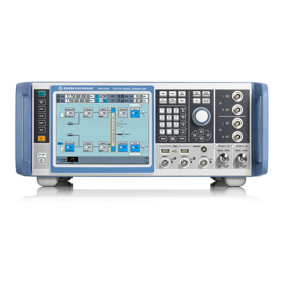
® Getting Started R&S SMW200A Instrument Tour Figure 2-1: Front panel view 1 = Touchscreen 2 = Utility keys 3 = ON/STANDBY 4 = Function keys 5 = Keypad 6 = Navigation controls 7 = I/Q input connectors 8 = USB connectors... - Page 69 ® Getting Started R&S SMW200A Instrument Tour Figure 2-2: Touchscreen elements 1 = Status bar (frequency and level display) 2 = Block diagram 3 = Taskbar/softkey bar A touchscreen is a screen that is touch-sensitive. It reacts in a specified way when a particular element on the screen is tapped by a finger.
-
Page 70: Keys
® Getting Started R&S SMW200A Instrument Tour Risk of touchscreen damage Inappropriate tools or excessive force can damage the touchscreen. Observe the following instructions when operating the touchscreen: ● Never touch the screen with ball point pens or other sharp objects, use your fingers instead. -
Page 71: Function Keys
® Getting Started R&S SMW200A Instrument Tour it is safe to switch off the AC power and disconnect the instrument from the power supply. Function Keys Function keys provide access to most common generator settings and functions. A detailed description of the corresponding functions is provided in the user manual. -
Page 72: Navigation Controls
® Getting Started R&S SMW200A Instrument Tour Type of key Description ESC key Closes all kinds of dialog boxes, if the edit mode is not active. Quits the edit mode, if the edit mode is active. In dialog boxes that contain a "Can- cel"... -
Page 73: Connectors
® Getting Started R&S SMW200A Instrument Tour Table 2-4: Navigation keys Type of key Description UP/DOWN Key The UP and the DOWN key does the following: ● In a numeric edit dialog box, increase or decrease the instrument parameter. ●... - Page 74 ® Getting Started R&S SMW200A Instrument Tour ● Connection of peripherals such as mouse or keyboard ● Connection of memory stick for file transfer ● Firmware update Note: Further USB interface type A (host USB) and a USB interface type B (USB DEVICE) are available on the rear panel.
-
Page 75: Rear Panel Tour
® Getting Started R&S SMW200A Instrument Tour Table 2-7: Overview of RF connector types depending on the frequency range Required option Connector type RF A: R&S SMW-B103/-B106 N female RF B: R&S SMW-B203/-B206 RF A: R&S SMW-B112 Test port adapter, PC 3.5 mm female RF B: R&S SMW-B212... - Page 76 ® Getting Started R&S SMW200A Instrument Tour 1, 2 = Connectors for use in a rack = IEC 625/IEEE 488 connector = REF IN/REF OUT connectors = INST TRIG X connectors = USER X connectors = EFC connectors = LO IN/LO OUT connectors...
-
Page 77: Connectors
® Getting Started R&S SMW200A Instrument Tour 2.2.2.1 Connectors Rear panel connectors, recommended for use of the instrument in a 19" rack. See also "Mounting in a rack" on page 40. RF A/RF B Rear panel connectors for the first RF path (option R&S SMW-B81/-B83) and the sec- ond RF path (option R&S SMW-B82/-B84). - Page 78 ® Getting Started R&S SMW200A Instrument Tour ● Yellow: an output connector ● No light: the connector is not active See also Chapter 11.2, "Configuring the Local and Global Connectors", on page 661 Chapter 11.2.4, "RF Connectors Settings", on page 667.
- Page 79 ® Getting Started R&S SMW200A Instrument Tour Main power switch function: ● Position 1: The instrument is in operation. ● Position 0: The entire instrument is disconnected from the AC power supply. For details, refer to Chapter 2.1.1.6, "Turning the Instrument On and Off",...
- Page 80 ® Getting Started R&S SMW200A Instrument Tour A dedicated LED indicates the connector status: ● Green: an input connector ● Yellow: an output connector ● No light: the connector is not active EXT X 1/2 Input for external analog modulation signals.
-
Page 81: Trying Out The Instrument
® Getting Started R&S SMW200A Trying Out the Instrument Hold the QSFP connector by its panes. Insert it in the HS DIG I/Q and push it. ● To disconnect the cable: Do not pull the cable itself. Puling the cable can damage the HS DIG I/Q inter- face. -
Page 82: Generating An Unmodulated Carrier
® Getting Started R&S SMW200A Trying Out the Instrument 2.3.1 Generating an Unmodulated Carrier We start out by generating a simple unmodulated signal. The R&S SMW in this exam- ple can be a base unit in its minimal configuration. 1. On the R&S SMW front panel, press the PRESET key to start out in a defined instrument configuration. - Page 83 ® Getting Started R&S SMW200A Trying Out the Instrument Figure 2-5: Block diagram: Generating an unmodulated signal Tip: Alternative way to access the instrument functions. To fulfill the same task, you can use other hot spots in the block diagram, the provided functions under the "RF"...
-
Page 84: Generating A Digitally Modulated Signal
® Getting Started R&S SMW200A Trying Out the Instrument ● Use the FREQ, LEVEL, and RF ON/OFF key on the front panel. See also Chapter 2.5, "Instrument Control", on page 106. The 1.95 GHz signal is output at the RF A connector at the front panel of the R&S SMW. - Page 85 ® Getting Started R&S SMW200A Trying Out the Instrument The "Custom Digital Modulation" dialog opens. 2. In the "Custom Digital Modulation" dialog, select "General > Set acc to standard > WCDMA-3GPP". 3. Select "General > State > On" to enable signal generation.
-
Page 86: Triggering The Instrument With An External Signal
® Getting Started R&S SMW200A Trying Out the Instrument Figure 2-7: Display of the used modulation type The instrument activates automatically "I/Q Mod A", uses the internal trigger and clock signals, and generates a WCDMA-3GPP signal, modulated with a QPSK 45°... - Page 87 ® Getting Started R&S SMW200A Trying Out the Instrument generation start time, determined by a defined trigger event, e.g. by triggering the instrument internally or externally from the DUT. This example illustrates the general principle of external triggering and extends the configuration performed in Chapter 2.3.2, "Generating a Digitally Modulated...
- Page 88 ® Getting Started R&S SMW200A Trying Out the Instrument The instrument uses its internal trigger and clock signals, and the default mapping of the marker signals to the connectors. 2. To access the related connector settings, perform one of the following: ●...
- Page 89 ® Getting Started R&S SMW200A Trying Out the Instrument Figure 2-9: Signal mapping to the global connectors The "Global Connectors" dialog displays the current connectors configuration. The settings are configurable, but in this example we use the default mapping. 3. Alternatively, select "Block Diagram > Baseband > Misc > Custom Digital Mod", select the ">...
- Page 90 ® Getting Started R&S SMW200A Trying Out the Instrument To reconfigure the trigger settings We assume that the instrument is configured as described in Chapter 2.3.2, "Generat- ing a Digitally Modulated Signal", on page 69 and the default connector mapping is...
- Page 91 ® Getting Started R&S SMW200A Trying Out the Instrument To connect the instrument and the external trigger source 1. Use a suitable cable to connect the external trigger source to the USER 3 connec- tor of the R&S SMW, see Figure 2-10.
-
Page 92: Enabling And Configuring A Marker Signal
® Getting Started R&S SMW200A Trying Out the Instrument 2. Use suitable cables to connect the RF A/B REF OUT connectors of the R&S SMW to the signal analyzer or the DUT. Upon the receiving of an external trigger event, the R&S SMW starts the signal generation and then generates a continuous signal. -
Page 93: Routing The Signal Through The Instrument And Defining The Output Connectors
® Getting Started R&S SMW200A Trying Out the Instrument In this example, we use the global USER connectors. Alternatively, you can achieve the same configuration goal with the local T/M/C connectors. ® This test setup requires one oscilloscope, like the R&S RTO, as additional equipment. - Page 94 ® Getting Started R&S SMW200A Trying Out the Instrument In the provided example, you use the R&S SMW to generate two baseband signals, apply a baseband frequency shift, weight them and add them. You then route the gen- erated stream and define the output connector. The initial situation is the configuration described in Chapter 2.3.3, "Triggering the Instrument with an External...
- Page 95 ® Getting Started R&S SMW200A Trying Out the Instrument The block diagram displays the routing. 3. In the block diagram, select "Baseband B > Misc > Custom Digital Mod...", select "Set acc. to standard > 3GPP FDD" and enable "Custom Digital Modulation > State >...
- Page 96 ® Getting Started R&S SMW200A Trying Out the Instrument 4. To apply frequency and power offsets to the signals, select "Baseband B > Base- band Offsets". a) Enter "Baseband A > Frequency Offset > 5 MHz". b) Enter "Baseband B > Frequency Offset > -5 MHz".
- Page 97 ® Getting Started R&S SMW200A Trying Out the Instrument To map the I/Q stream and define the output connector The term stream describes the signal at the input of the "I/Q Stream Mapper" up to the output connectors of the instrument.
-
Page 98: Verifying The Generated Signal With The Graphics Display
® Getting Started R&S SMW200A Trying Out the Instrument The generated composed signal (stream A) is output at the analog RF A connector and routed to the I/Q OUT 1 connector. The block diagram confirms this routing and displays the letter "A" next to the symbols of the output connectors. - Page 99 ® Getting Started R&S SMW200A Trying Out the Instrument a) Select "Taskbar > System Configuration > Graphics" b) On the "Taskbar", tap the wave icon. The "Graphics Configuration" dialog opens. To visualize the sum signal 1. In the "Graphics Configuration" dialog, select "Mode > Power Spectrum".
- Page 100 ® Getting Started R&S SMW200A Trying Out the Instrument A new thumbnail (minimized view) indicating the active diagram appears in the "Taskbar". 4. Press the thumbnail graphic. The graphic enlarges and the diagram is displayed in a normal size The "Power Spectrum" displays two signals, both 3GPP FDD signals are frequency shifted and the right one is also attenuated.
-
Page 101: Saving And Recalling Settings
® Getting Started R&S SMW200A Trying Out the Instrument See also Chapter 8, "Monitoring Signal Characteristics", on page 559. 2.3.7 Saving and Recalling Settings To restore the results of our measurements later, we store the instrument settings to a file. - Page 102 ® Getting Started R&S SMW200A Trying Out the Instrument 3. Tap the "Save" button. The file MyTestSignal.savrcltxt is stored in the default directory /var/ user. To load stored instrument settings You can restore the settings to the instrument at any time using the settings file.
- Page 103 ® Getting Started R&S SMW200A Trying Out the Instrument How to display all parameters with values different to their preset values When you load a file to your instrument, you may do not have enough information on the changed settings. In such case, it is useful to visualize all parameters that have been changed from their default state.
-
Page 104: Generating An Eutra/Lte Signal
® Getting Started R&S SMW200A Trying Out the Instrument 2.3.8 Generating an EUTRA/LTE Signal The main application field of the R&S SMW is the generation of digital signals in accordance with several telecommunication and wireless standards, like WCDMA, EUTRA/LTE or WLAN, to name a few. This example uses the digital standard EUTRA/LTE to introduce the way you can access and interact with the instrument and experience the advantages provided by the additional options. - Page 105 ® Getting Started R&S SMW200A Trying Out the Instrument As in the user interfaces of all digital standards, the "EUTRA/LTE" dialog is divided into several tabs. The "General" tab comprises the primary settings of the standard, the functions for storing and recalling settings and provides access to further func- tions and dialogs, like the "Filter"...
- Page 106 ® Getting Started R&S SMW200A Trying Out the Instrument Close the dialog. 6. On the "Status Bar", tap the "Freq" and "Lev" fields and enter new values, for example 2.1432 GHz and -20 dBm. User Manual 1175.6632.02 ─ 16...
-
Page 107: Using The System Configuration Capabilities For Mimo Setups
With these first steps, you have gained an impression of the provided functionality. For a comprehensive description of the full range of capabilities, refer to the user man- ual "EUTRA/LTE Digital Standard for R&S SMW200A". 2.3.9 Using the System Configuration Capabilities for MIMO Setups The R&S SMW supports versatile MIMO configurations and provides comfortable func-... - Page 108 ® Getting Started R&S SMW200A Trying Out the Instrument To learn more and to explore the whole range of capability provided by the "System Configuration" function, in particular how to connect and configure external devices, refer to Chapter 3, "Signal Routing and System Configuration",...
- Page 109 ® Getting Started R&S SMW200A Trying Out the Instrument The "System Configuration > Fading/Baseband Configuration" dialog displays the current signal routing. The instrument works in the default "Standard" mode. Figure 2-13: System Configuration in the default Standard Mode 1 = Standard or advanced mode; the last is required for configuration of complex LxMxN MIMO scenar-...
- Page 110 ® Getting Started R&S SMW200A Trying Out the Instrument Figure 2-14: System Configuration in the Advanced Mode (1x2x2 configuration) 1 = Advanced mode, required for configuration of complex LxMxN MIMO scenarios 2 = Current signal routing; 2x2 MIMO configuration 3 = Separated and coupled baseband sources 4 = Simplified preview diagram of the particular configuration 2.
- Page 111 ® Getting Started R&S SMW200A Trying Out the Instrument In coupled baseband source mode, the R&S SMW takes over the baseband signal configuration. The instrument adjusts the settings in the basebands automatically, for example the mapping of the transmitting antennas to the basebands.
-
Page 112: System Overview
® Getting Started R&S SMW200A System Overview 2.4 System Overview This section helps you to get familiar with the R&S SMW. It provides an introduction to the general concept of the instrument with a sample of the possible application fields. - Page 113 ® Getting Started R&S SMW200A System Overview The following examples do not cover all possible cases but aim to introduce the way the block diagram depicts the installed options. ● An example of a base unit, equipped with one signal path (R&S SMW-B10, R&S SMW-B13, and R&S SMW-B103/-B106)
- Page 114 ® Getting Started R&S SMW200A System Overview Figure 2-16: Block diagram of a fully equipped two path instrument (4x4 MIMO configura- tion) For more examples, see also Chapter 2.4.2, "Applications Examples of the R&S SMW", on page 102. The cross-reference between the installed options and the displayed settings...
-
Page 115: Internal Baseband Source ("Baseband" Blocks)
® Getting Started R&S SMW200A System Overview Functional block Required option "I/Q Analog B" R&S SMW-B13T "I/Q Digital A" R&S SMW-K18 "I/Q Digital B" Second option R&S SMW-K18 "RF A" R&S SMW-B103/-B106 "RF B" R&S SMW-B203/-B206 2.4.1.3 Internal Baseband Source ("Baseband" Blocks) The "Baseband"... -
Page 116: Fading Simulator ("Fading" Blocks)
® Getting Started R&S SMW200A System Overview The external digital I/Q signals are further processed in the baseband section (e.g. fading, addition of noise) ● The signal routing (in the standard "classic" mode) The external and internal baseband signals can be routed and added (possibly with frequency, phase and power offsets). -
Page 117: I/Q Modulator ("I/Q Mod" Blocks)
® Getting Started R&S SMW200A System Overview 2.4.1.8 I/Q Modulator ("I/Q Mod" Blocks) The "I/Q Mod" blocks represent the I/Q modulators. These functional blocks are the access point to: ● The I/Q modulation of the internal baseband signal ● The I/Q modulation of an external analog wideband signal (single ended or differ- ential) ●... -
Page 118: Transmit Diversity Test (Miso Scenario)
® Getting Started R&S SMW200A System Overview ● Generation of signals with up to 2 GHz signal bandwidth, for example for WLAN IEEE 802.11ad signals ● Generation of fading scenarios, e.g for test setups involving R&S SMW and ® R&S A few examples are given in the following: ●... -
Page 119: Generation Of Signals For Testing Of Wcdma Handover (Two Cells)
® Getting Started R&S SMW200A System Overview 2.4.2.3 Generation of Signals for Testing of WCDMA Handover (Two Cells) The block diagram in this example depicts the generation of a test signal using both internal baseband generators and both RF outputs, for example for handover tests. -
Page 120: Generation Of An Lte Test Signal With Carrier Aggregation And 2X2 Mimo Each Com Ponent Carrier
® Getting Started R&S SMW200A System Overview 2.4.2.5 Generation of an LTE Test Signal with Carrier Aggregation and 2x2 MIMO each Component Carrier The block diagram in this example depicts the generation of an EUTRA/LTE test signal with two component carriers (intra-band carrier aggregation) and 2x2 MIMO fading each, for example for UE tests. -
Page 121: Possible Ways To Operate The Instrument
® Getting Started R&S SMW200A Instrument Control 2.4.2.6 Generation of a WLAN 802.11ad Signal with 1.76 GHz Bandwidth The block diagram in this example depicts the generation of a WLAN 802.11ad test signal with 1.76 GHz bandwidth. The instrument uses one internal wideband baseband generator with 2 GHz bandwidth and one RF output. -
Page 122: Instrument Control
® Getting Started R&S SMW200A Instrument Control Create programs to automatize repeating settings, tests and measurements. The instrument is connected to a computer running the program. This way of operation is described in Chapter 12, "Network Operation and Remote Control", on page 702. -
Page 123: 2.5.3 Understanding The Display Information
® Getting Started R&S SMW200A Instrument Control Throughout the manual, the term "select" refers to any of the described methods, i.e. using a finger on the touchscreen, a mouse pointer in the display, or a key on the instrument or on a keyboard. -
Page 124: Block Diagram
® Getting Started R&S SMW200A Instrument Control 1 = Frequency display 2 = Status buttons 3 = Level display The status buttons indicate key parameters that are set for the output signal. Most of the status buttons are virtual keys you can use to open a corresponding menu or dia- log. -
Page 125: Taskbar
® Getting Started R&S SMW200A Instrument Control Starting from left up to the "Stream Mapper", you can see the functional blocks provi- ded in the baseband domain. After the stream mapper, the analog section contains the digital to analog conversion and modulation to RF. -
Page 126: Additional Display Characteristics
® Getting Started R&S SMW200A Instrument Control Whenever you open a settings or graphics dialog, it is automatically assigned to the "Taskbar". The softkeys shown in the following figure represent the variants. Figure 2-18: Taskbar fully assigned 1 = System configuration 2 = Remote control connections 3 = R&S NRP power sensors... - Page 127 ® Getting Started R&S SMW200A Instrument Control As additional means of interacting with the instrument without having to connect an external keyboard, either a numerical or alphanumerical on-screen keypad appears when you activate an entry field (see Chapter 2.5.5, "Entering Data",...
-
Page 128: 2.5.4 Accessing The Functionality
® Getting Started R&S SMW200A Instrument Control 2.5.4 Accessing the Functionality All functionalities are provided in dialog boxes as known from computer programs. You can control the instrument intuitively with the touchscreen. This section provides an overview of the accessing methods. -
Page 129: 2.5.5 Entering Data
® Getting Started R&S SMW200A Instrument Control To minimize a dialog box ► Tap the "Minimize" icon in the upper right corner. To close a dialog box ► Tap the "Close" icon in the upper right corner. Press the ESC key on the front panel. -
Page 130: Entering Numeric Parameters
® Getting Started R&S SMW200A Instrument Control Completing the entry ► Press the ENTER key or the rotary knob. Aborting the entry ► Press the ESC key. The dialog box closes without changing the settings. 2.5.5.1 Entering Numeric Parameters To enter values with the on-screen keypad If a field requires numeric input, the keypad provides only numbers. -
Page 131: 2.5.6 Getting Information And Help
® Getting Started R&S SMW200A Instrument Control "Redo" restores a previously undone action. 2.5.6 Getting Information and Help In some dialog boxes, graphics are included to explain the way a setting works. For further information, you can use the following sources: ●... - Page 132 ® Getting Started R&S SMW200A Instrument Control Contents of the help dialog box The help dialog box covers two main areas: ● "Contents" - contains a table of help contents ● "Topic" - contains a specific help topic The help system also provides an "Index" and a "Find" area, and "Zoom" functions that are accessed via the corresponding buttons.
-
Page 133: Using The Tutorials
® Getting Started R&S SMW200A Instrument Control 5. Use the "scroll bars" to shift the visible section of content shown. 6. To maximize the "Topics" area, tap the "Hide Contents Tree" button to hide the contents tree. Using the index 1. - Page 134 ® Getting Started R&S SMW200A Instrument Control 4. Tap on a tutorial from the list and confirm with "Select". If the file contains a description, it is displayed. 5. Use the default mode, that is "Execution Mode > Interactive". 6. Tap on the "Start" button.
- Page 135 ® Getting Started R&S SMW200A Instrument Control 1 = Information on the performed action 2 = Progress bar 3 = "Next Step": confirms the execution of the step 4 = "Stop": terminates the tutorial 8. To execute a subsequent step, select the "Next Step" button.
-
Page 136: 2.5.7 Remote Control
® Getting Started R&S SMW200A Instrument Control 2.5.7 Remote Control In addition to working with the R&S SMW interactively, located directly at the instru- ment, it is also possible to operate and control it from a remote PC. The R&S SMW supports various methods for remote control: ●... -
Page 137: Signal Routing And System Configuration
® Signal Routing and System Configuration R&S SMW200A How the System Configuration Function Supports You in Your Task 3 Signal Routing and System Configuration The R&S SMW provides multiple routing possibilities and simplifies the definition of versatile MIMO configurations. Provided the instrument is equipped with the required options, R&S SMW can: ●... - Page 138 ® Signal Routing and System Configuration R&S SMW200A How the System Configuration Function Supports You in Your Task required that you are familiar with the instrument's capability so that you can evaluate if and which additional instruments are required in the current test setup.
-
Page 139: From A Test Scenario To The Required System Configuration
® Signal Routing and System Configuration R&S SMW200A How the System Configuration Function Supports You in Your Task 3.1.2 From a Test Scenario to the Required System Configuration The information in Table 3-1 provides a cross-reference between a test scenario and the required configuration. - Page 140 ® Signal Routing and System Configuration R&S SMW200A How the System Configuration Function Supports You in Your Task Test scenario Short description/application Fading and Baseband Required output sig- Required addi- Baseband Source nals per instrument tional instru- Config. Configura- ments tion ●...
-
Page 141: Possible Ways To Configure The Signal Flow
® Signal Routing and System Configuration R&S SMW200A Possible Ways to Configure the Signal Flow Table 3-2: Example of scenarios for signaling tests Test scenario Short description/application Fading and Baseband Required Input/ Required Baseband Source output signals per additional Configuration... -
Page 142: Using The System Configuration Capabilities
® Signal Routing and System Configuration R&S SMW200A Possible Ways to Configure the Signal Flow Signal routing This is an easy method for a simple signal routing task involving routing and summing of the baseband signals up to the output of the "Fading" block. The available routing possibilities are grouped in the "Signal Routing"... - Page 143 ® Signal Routing and System Configuration R&S SMW200A Possible Ways to Configure the Signal Flow For any allowed system configuration, the R&S SMW configures the signal flow automatically upon just four parameters: – Number of entities (users or cells) –...
-
Page 144: Overview Of The Input And Output Signals And Interfaces
® Signal Routing and System Configuration R&S SMW200A Overview of the Input and Output Signals and Interfaces I/Q stream mapper Irrespectively of the used signal routing method, it is possible to reconfigure the distri- bution and mapping of the I/Q streams to the output connectors. -
Page 145: Physical Location Of The Input And Output Interfaces
® Signal Routing and System Configuration R&S SMW200A Overview of the Input and Output Signals and Interfaces Logical signals, streams and channels at the interfaces This section provides background information and introduction to the topics. The description is divided in parts that follow the logical decision process when configuring the instrument. - Page 146 ® Signal Routing and System Configuration R&S SMW200A Overview of the Input and Output Signals and Interfaces Figure 3-1: Location of the digital input and output interfaces (part view of the rear panel of a fully equipped instrument) ● Figure 3-2 shows the analog output interfaces on the rear panel together with the associated GUI term (highlighted in orange color).
-
Page 147: Overview Of The Baseband Signal Sources
® Signal Routing and System Configuration R&S SMW200A Overview of the Input and Output Signals and Interfaces Indication of the digital interface status A dedicated LED indicates the connector status: ● Green: an input connector ● Yellow: an output connector ●... -
Page 148: Overview Of The Baseband And Rf Output Signals
® Signal Routing and System Configuration R&S SMW200A Overview of the Input and Output Signals and Interfaces ● Used as a user-specific wanted signal or interference signals to the internally gen- erated signals ● Routed to one or to all the signal paths, added to the internally generated base- band signal possibly also frequency shifted ●... - Page 149 ® Signal Routing and System Configuration R&S SMW200A Overview of the Input and Output Signals and Interfaces Sample rate The sample rate of the digital input and output signal can be defined manually or auto- matically retrieved from the input and estimated for the output signal.
-
Page 150: Specific Characteristics Of The Digital I/Q Interface
® Signal Routing and System Configuration R&S SMW200A Overview of the Input and Output Signals and Interfaces Why the instrument monitors the signal internally and how to avoid overflow The R&S SMW constantly monitors the input and output digital signal and indicates an overflow status. - Page 151 ® Signal Routing and System Configuration R&S SMW200A Overview of the Input and Output Signals and Interfaces 2) perform one measurement for each baseband source 3) set the measurement period to a time value that is long enough to capture several periods of the input signal.
-
Page 152: Specifics Of The Analog I/Q Interfaces
® Signal Routing and System Configuration R&S SMW200A System Configuration Settings 3.3.4.2 Specifics of the Analog I/Q Interfaces The R&S SMW outputs the digitally modulated signal not only directly but also conver- ted to an analog I/Q baseband output signal. The R&S SMW outputs the analog base- band signal single ended or differential (non-inverted);... -
Page 153: Fading And Baseband Configuration Settings
® Signal Routing and System Configuration R&S SMW200A System Configuration Settings For a step-by-step description of how to use the provided settings, refer to Chapter 3.9, "How to Connect External Instruments and Configure the Signal Flow", on page 191 . - Page 154 ® Signal Routing and System Configuration R&S SMW200A System Configuration Settings ● Select "Block Diagram > I/Q Stream Mapper > System Configuration > Fading/ Baseband Config" ● On the instrument front panel, press SETUP. Select "System Configuration > Fading/Baseband Config"...
-
Page 155: Set To Default
® Signal Routing and System Configuration R&S SMW200A System Configuration Settings └ Streams (Rx Antennas).................142 Subset......................... 142 Baseband Source Configuration................. 143 Duplicate Streams.......................143 Apply........................... 144 Ok..........................144 Set to Default Presets the signal routing in the baseband section and the fading configuration to the default state. -
Page 156: Signal Routing
® Signal Routing and System Configuration R&S SMW200A System Configuration Settings "Digital Only/Digital Only Multiplexed" Option: R&S SMW-K551 R&S SMW can generate digital signals with reduced speed, depend- ing on the device connected to the digital I/Q interfaces. The supported configuration and mapping of the generated streams to the digital I/Q interfaces depends on the selected mode: ●... -
Page 157: Bb Signals (Tx Antennas)
® Signal Routing and System Configuration R&S SMW200A System Configuration Settings Table 3-5: Available value ranges and allowed combinations Number of entities (L) Number of base- Number of streams Baseband Source Configu- bands (Tx antennas) (Rx antennas) ration 1 to 4... - Page 158 ® Signal Routing and System Configuration R&S SMW200A System Configuration Settings An 1x8x8 MIMO configuration requires two R&S SMW, where each of the instruments generates a subset of 32 fading channels, out of the total 64 channels. This parameter defines which fading channels from the MIMO matrix are calculated by the selected instrument.
-
Page 159: I/Q Stream Mapper Settings
® Signal Routing and System Configuration R&S SMW200A System Configuration Settings The pair of streams created out of the same baseband are identical, in terms of con- tent, power level and frequency. The streams are treated as individual streams in terms of adding AWGN and shifting within the available RF bandwidth. - Page 160 ® Signal Routing and System Configuration R&S SMW200A System Configuration Settings The dialog provides the settings for routing of the signal streams to the available output connectors, the analog RF and I/Q output, and the digital I/Q output connec- tors.
- Page 161 ® Signal Routing and System Configuration R&S SMW200A System Configuration Settings Phase, deg Sets the phase offset of the corresponding stream. Remote command: on page 841 :SCONfiguration:OUTPut:MAPPing:STReam<st>:POFFset Map Stream X to Connector The mapping of the generated streams to the output connectors is represented as a stream matrix.
-
Page 162: External Rf And I/Q Settings
® Signal Routing and System Configuration R&S SMW200A System Configuration Settings 3.4.3 External RF and I/Q Settings A fully equipped R&S SMW can deliver up to 8 independent I/Q streams but can modu- late only two of them to the RF domain using the internal RF paths. The remaining streams can be output at the analog or digital I/Q interfaces and led to the connected external RF signal generators. -
Page 163: Connections Configuration And Connection Status Overview Settings
® Signal Routing and System Configuration R&S SMW200A System Configuration Settings Access: ► Select "Taskbar > System Config > System Configuration > External RF and I/Q". The dialog provides an overview of all available I/Q input and output connectors and comprises the settings necessary to establish the connection to the external instruments. -
Page 164: Settings: Display
® Signal Routing and System Configuration R&S SMW200A System Configuration Settings Settings: Display........................149 Auto Connect......................149 Connect/Disconnect All Remote................. 149 Preset behavior: Keep connections to external instruments........150 Connector Name......................150 Direction........................151 External Instrument..................... 152 Connection......................152 Remote Connection Status.................. -
Page 165: Preset Behavior: Keep Connections To External Instruments
® Signal Routing and System Configuration R&S SMW200A System Configuration Settings Remote connection status can be toggled with the parameter Remote Connection Sta- tus. Note: Disconnecting the remote connection to a R&S SZU presets several RF parame- ters of the R&S SMW to their default value. -
Page 166: Direction
® Signal Routing and System Configuration R&S SMW200A System Configuration Settings The dialog lists the connectors, required for the current "Fading and Baseband Config- uration". See also: ● Chapter 3.3.1, "Physical Location of the Input and Output Interfaces", on page 130 ●... -
Page 167: External Instrument
® Signal Routing and System Configuration R&S SMW200A System Configuration Settings Remote command: on page 845 :SCONfiguration:EXTernal:CODer<ch>:DIRection? on page 845 :SCONfiguration:EXTernal:FADer<ch>:DIRection? on page 845 :SCONfiguration:EXTernal:BBMM<ch>:DIRection? on page 845 :SCONfiguration:EXTernal:IQOutput<ch>:DIRection? External Instrument Accesses a dialog with settings that help you to establish the connection to the exter- nal instruments, see Chapter 3.4.3.2, "External Instrument Configuration... -
Page 168: Instrument Name
® Signal Routing and System Configuration R&S SMW200A System Configuration Settings To connect/disconnect all external instruments, use the functions Connect/Disconnect Remote. Note: External instruments connected to the R&S SMW are preset (:DEVice:PRESet) whenever: ● The connection to the external instrument is established or terminated ("Connect/ Disconnect All Remote"... -
Page 169: (Delta) Rf Frequency/ Rf Level
® Signal Routing and System Configuration R&S SMW200A System Configuration Settings Remote command: on page 847 :SCONfiguration:EXTernal:FADer<ch>:RF:COUPling on page 847 :SCONfiguration:EXTernal:BBMM<ch>:RF:COUPling on page 847 :SCONfiguration:EXTernal:IQOutput<ch>:RF:COUPling (Delta) RF Frequency/ RF Level In uncoupled mode, sets the RF frequency and RF level of the external instrument. -
Page 170: Remote Config Settings
® Signal Routing and System Configuration R&S SMW200A System Configuration Settings Select "External Instruments > Config ...". The "<Dig. Conn. Name>: External Instrument Configuration" dialog opens and dis- plays the "External Instrument Configuration > Remote Config" settings. Settings: Remote Config Settings....................155 Initialization Sequence Settings.................. - Page 171 ® Signal Routing and System Configuration R&S SMW200A System Configuration Settings Settings: Detect/Scan.........................156 Purge/Clean........................ 156 Select Instrument......................157 Symbolic Name......................157 Hardware Channel...................... 157 Name / IP Address...................... 157 Path........................157 I/Q Output Type......................158 Apply........................... 158 Apply and Connect......................158 Detect/Scan If you connect an external instrument, you can fill in the required information in the "External Instrument Configuration"...
- Page 172 ® Signal Routing and System Configuration R&S SMW200A System Configuration Settings Select Instrument Lists all available instruments, found by the Detect/Scan function. To connect an external instrument, use one of the following: ● Enable "Select Instrument > New" and configure the settings manually ●...
- Page 173 ® Signal Routing and System Configuration R&S SMW200A System Configuration Settings Remote command: on page 850 :SCONfiguration:EXTernal:REMote:ADD on page 852 :SCONfiguration:EXTernal:CODer<ch>:REMote:INFO? on page 852 :SCONfiguration:EXTernal:FADer<ch>:REMote:INFO? on page 852 :SCONfiguration:EXTernal:BBMM<ch>:REMote:INFO? on page 852 :SCONfiguration:EXTernal:IQOutput<ch>:REMote:INFO? I/Q Output Type Selects the type of output signal.
-
Page 174: Initialization Sequence Settings
® Signal Routing and System Configuration R&S SMW200A System Configuration Settings on page 851 :SCONfiguration:EXTernal:BBMM<ch>:REMote:CONNect on page 851 :SCONfiguration:EXTernal:IQOutput<ch>:REMote:ISELect on page 851 :SCONfiguration:EXTernal:IQOutput<ch>:REMote:CONNect Initialization Sequence Settings Access: 1. Select "Taskbar > System Config > System Configuration > External RF and I/Q". - Page 175 ® Signal Routing and System Configuration R&S SMW200A System Configuration Settings ● Sends the content of the initialization sequence file to reconfigure the external instrument If necessary, perform further settings and configuration of the external instruments. Tip: Try out also the following: ●...
-
Page 176: Remote Control Settings
® Signal Routing and System Configuration R&S SMW200A System Configuration Settings Remote Control Settings Access: 1. Select "Taskbar > System Config > System Configuration > External RF and I/Q". 2. Navigate to the required connector. Select "External Instruments > Config ...". -
Page 177: Show Connector
® Signal Routing and System Configuration R&S SMW200A System Configuration Settings Mode You can send a single command ("Command") or a command sequence ("Sequence") to the connected instrument. Command, Send Command Entry field for the SCPI commands. You can enter a new command or select a previously sent command from the "His- tory". -
Page 178: Check Connections Settings
® Signal Routing and System Configuration R&S SMW200A System Configuration Settings 3. In the "<Dig. Conn. Name>: External Instrument Configuration" dialog, select "Show Connector". The dialog displays the location of the selected connector. The "Show Connector" function triggers the instrument to identify the connector on the rear panel. -
Page 179: Overview
® Signal Routing and System Configuration R&S SMW200A System Configuration Settings 4. Select "Check Connection". The dialog is a graphical representation of the required connections and their sta- tus. The connection status indication is color coded. The dialog shows information on the following: ●... - Page 180 ® Signal Routing and System Configuration R&S SMW200A System Configuration Settings 1 = I/Q streams mapped to the interfaces 2a = State indication for the RF and digital/analog IQ outputs: active 2b = State indication for the RF and digital/analog IQ outputs: inactive 3 = External instrument configured in the "External RF and I/Q"...
-
Page 181: Signal Routing Settings
® Signal Routing and System Configuration R&S SMW200A Signal Routing Settings GUI element Dialog Refer to "FAD 1/2" Depends on the current Chapter 3.6, "Digital Baseband Input Settings", configuration and on page 170 or the associated stream whether the digital inter- Chapter 3.7, "I/Q Digital Output... - Page 182 ® Signal Routing and System Configuration R&S SMW200A Signal Routing Settings ● The external baseband signal of the first input module "BB Input A" can be fed into path A, path B or both ● The second baseband input module "BB Input B" is firmly connected to signal path ●...
- Page 183 ® Signal Routing and System Configuration R&S SMW200A Signal Routing Settings Example: Baseband and fading signal routing in standard mode Figure 3-6 shows an example of the signal flow for the following signal routing set- tings: ● "Baseband A > Signal Routing > route to path A and B"...
- Page 184 ® Signal Routing and System Configuration R&S SMW200A Signal Routing Settings Example: Routing the signal of baseband A to the RF B output Figure 3-7 shows an example of the signal flow for the following settings: ● "IQ Stream Mapper > Stream A to RF B"...
-
Page 185: Digital Baseband Input Settings
® Signal Routing and System Configuration R&S SMW200A Digital Baseband Input Settings Signal Routing (requires R&S SMW-B10) Defines the way the baseband signal (internally generated or externally provided) is routed in the instrument. When routing more than one signals to the same path, the signals are summed. - Page 186 ® Signal Routing and System Configuration R&S SMW200A Digital Baseband Input Settings To access and configure the "Baseband Input" settings The "BB Input" block provides access to the settings for signal routing, frequency offset and path gain, and to the available configuration parameters of the external signal.
-
Page 187: General Settings
® Signal Routing and System Configuration R&S SMW200A Digital Baseband Input Settings Figure 3-9: Example: "Baseband Input Settings" in 2x2x2 System Configuration If the current instrument configuration uses Coupled sources, the dialog consists of up to four side tabs, whereas the number of tabs corresponds to the number of... -
Page 188: Sample Rate Settings
® Signal Routing and System Configuration R&S SMW200A Digital Baseband Input Settings Settings: State..........................173 Source.........................173 Swap........................173 Connected Device.......................173 State Switches On/Off the feeding of the selected external digital signals into the baseband. Remote command: on page 866 [:SOURce<hw>]:BBIN:STATe Source Defines the connector used as an external signal source. - Page 189 ® Signal Routing and System Configuration R&S SMW200A Digital Baseband Input Settings Settings: Sample Rate Source....................174 Sample Rate Value..................... 174 Sample Rate Source Selects whether the sample rate is estimated based on the digital input signal or is a manually entered value (see also Chapter 3.3.4, "Important Signal Parameters and...
-
Page 190: Input Level Settings
® Signal Routing and System Configuration R&S SMW200A Digital Baseband Input Settings 3.6.3 Input Level Settings Access: ► Select "BB Input > Digital I/Q In > Baseband Input Settings > Input Level". Settings: DIG IQ Auto Setting....................175 Measurement Period....................176 Auto Level Set......................176... -
Page 191: Signal Monitoring Settings
® Signal Routing and System Configuration R&S SMW200A Digital Baseband Input Settings Measurement Period (for CODER connectors) Sets the recording duration for measuring the baseband input signal by "Auto Level Set". Note: For accurate level measurements, set the measurement period to a time value that is long enough to capture several periods of the input signal. - Page 192 ® Signal Routing and System Configuration R&S SMW200A Digital Baseband Input Settings Settings: Signal Monitoring......................177 Signal Monitoring The R&S SMW monitors constantly the input signal (Crest Factor and Peak Level) and indicates an overflow status, if the entered "Peak Level" (in dB full scale) value does not correspond with the real value.
-
Page 193: I/Q Digital Output Settings
® Signal Routing and System Configuration R&S SMW200A I/Q Digital Output Settings 3.7 I/Q Digital Output Settings Required Options The equipment layout for output of digital I/Q signal includes: ● Option Baseband Generator (R&S SMW-B10) per signal path and Option Baseband main module, one/two I/Q paths to RF (R&S SMW-B13/-B13T) ●... - Page 194 ® Signal Routing and System Configuration R&S SMW200A I/Q Digital Output Settings Figure 3-11: Representation of the digital output interface in advanced mode 1 = digital output interface state: gray = inactive; blue = active 2 = more settings indication; select to unfold detailed information 1.
-
Page 195: General Settings
® Signal Routing and System Configuration R&S SMW200A I/Q Digital Output Settings Figure 3-12: I/Q Digital Outputs: Understanding the displayed information = Side tabs; one per digital output = State of the digital output = Digital output interface name = Mapped I/Q streams 5a, 5b = Indicates the connected instrument Using the "I/Q Stream Mapper"... - Page 196 ® Signal Routing and System Configuration R&S SMW200A I/Q Digital Output Settings If R&S SGT is connected to the DIG I/Q interface of the R&S SMW, several parame- ters set automatically. Settings: State..........................181 Sample Rate Source....................181 Sample Rate Value..................... 181 Connected Device.......................181...
-
Page 197: Signal Output Settings
® Signal Routing and System Configuration R&S SMW200A I/Q Digital Output Settings 3.7.2 Signal Output Settings Access: ► Select "I/Q Digital > I/Q Digital Settings > Signal Output". If R&S SGT is connected to the DIG I/Q interface of the R&S SMW, "User Varia- tion"... - Page 198 ® Signal Routing and System Configuration R&S SMW200A I/Q Digital Output Settings Signal Output Comprises the level settings of the output signal. The signal level is expressed as a peak or RMS level value. If R&S SGT is connected to the DIG I/Q interface of the R&S SMW, the level parame- ters are set automatically.
- Page 199 ® Signal Routing and System Configuration R&S SMW200A I/Q Digital Output Settings "Overflow/No Overflow" Indicates whether the I/Q output signal is clipped or not. An additional indication is displayed in the block diagram close to the correspond- ing connector. Remote command: on page 1060 [:SOURce]:IQ:OUTPut:DIGital:BBMM<ch>:OFLow:STATe?
-
Page 200: I/Q Analog Output Settings
® Signal Routing and System Configuration R&S SMW200A I/Q Analog Output Settings 3.8 I/Q Analog Output Settings Required Options The equipment layout for output of analog I/Q signal includes: ● Option Standard Baseband Generator (R&S SMW-B10) per signal path and Option Baseband main module, one/two I/Q paths to RF (R&S SMW-B13/-B13T) - Page 201 ® Signal Routing and System Configuration R&S SMW200A I/Q Analog Output Settings The dialog comprises the settings for selecting the analog output signal type (sin- gle-ended or differential), enabling and generating an RF envelope signal, and adding digital impairments to the signal.
-
Page 202: Settings: State
® Signal Routing and System Configuration R&S SMW200A I/Q Analog Output Settings ● is the offset between inverting and non-inverting output as set with the offset parameter Offset (EMF) For more information, see data sheet. Related settings ● Chapter 3.8.1, "General Analog I/Q Output Settings",... -
Page 203: Save/Recall
® Signal Routing and System Configuration R&S SMW200A I/Q Analog Output Settings Parameter Value Depends on "System Configuration > External RF and I/Q > Preset behavior: "I/Q Output Type" Keep connections to external instruments": ● "Off": Single Ended ● "On": Not affected by the "Set to Default"... -
Page 204: Mode
® Signal Routing and System Configuration R&S SMW200A I/Q Analog Output Settings ● "Differential" If "RF Envelope > On" The inverted envelope signal Ē is output at the I BAR connectors. ● If "RF Envelope > Off" The analog I/Q signal components are output at the I/Q BAR con- nectors. -
Page 205: Offset (Emf)
® Signal Routing and System Configuration R&S SMW200A I/Q Analog Output Settings Effect of a positive bias Effect of a negative bias In "Single Ended" mode, this parameter defines the bias between the output signal and ground. It can be used to define the operating point of a DUT. -
Page 206: How To Connect External Instruments And Configure The Signal Flow
® Signal Routing and System Configuration R&S SMW200A How to Connect External Instruments and Configure the Signal Flow Remote command: on page 1055 [:SOURce<hw>]:IQ:OUTPut[:ANALog]:OFFSet:I on page 1055 [:SOURce<hw>]:IQ:OUTPut[:ANALog]:OFFSet:Q 3.9 How to Connect External Instruments and Configure the Signal Flow This section gives examples on the following topics: ●... -
Page 207: Finding Out The Suitable Configuration For Your Test Situation
® Signal Routing and System Configuration R&S SMW200A How to Connect External Instruments and Configure the Signal Flow ● How to Connect and Configure External Instruments........... 198 ● How to Generate a 2x8 MIMO Signal for BS Tests..........207 ● How to Generate a 8x8 MIMO Signal with Two R&S SMW........ -
Page 208: How To Define The Mimo Scenario
® Signal Routing and System Configuration R&S SMW200A How to Connect External Instruments and Configure the Signal Flow 3. In the "External Instrument Configuration" dialog, select "Show Connector". A blinking LED on the rear of the instrument indicates the connector's position. - Page 209 ® Signal Routing and System Configuration R&S SMW200A How to Connect External Instruments and Configure the Signal Flow Proceed as follows: 1. To access the "Fading/Baseband Configuration" settings, use one of the following: ● Select "Taskbar > System Config > System Configuration"...
- Page 210 ® Signal Routing and System Configuration R&S SMW200A How to Connect External Instruments and Configure the Signal Flow Figure 3-16: Signal routing example (Fading and Baseband Configuration > 1x4x4 and Coupled Baseband Sources) To define the baseband signal To generate an EUTRA/LTE signal, use the following general steps: 1.
-
Page 211: How To Route The I/Q Streams To The Output Interfaces
® Signal Routing and System Configuration R&S SMW200A How to Connect External Instruments and Configure the Signal Flow 5. Select "RF A > On" and "RF B > On". 3.9.4 How to Route the I/Q Streams to the Output Interfaces This example shows how to enable the instrument to output the EUTRA/LTE 1x4x4 MIMO signal at both RF outputs and both I/Q analog outputs. -
Page 212: How To Cable The Instruments In Mimo Test Setups
® Signal Routing and System Configuration R&S SMW200A How to Connect External Instruments and Configure the Signal Flow Tip: To route more streams to one output connector, in the"I/Q Stream Mapper" dialog and for the particular connector, select "Combination> Add" and select the streams to be routed to it. -
Page 213: How To Connect And Configure External Instruments
® Signal Routing and System Configuration R&S SMW200A How to Connect External Instruments and Configure the Signal Flow Figure 3-17: Example of test setup: 1x4x4 MIMO with R&S SMW and 2xR&S SGS connected to the I/Q OUT 1/2. Blue circle = front panel connector... - Page 214 ® Signal Routing and System Configuration R&S SMW200A How to Connect External Instruments and Configure the Signal Flow To connect instruments to the I/Q analog interface In this example, we assume a "Fading/Baseband Configuration > 1x4x4 MIMO" and the following stream mapping: Stream A and B are output at RF A and B; stream C and D at I/Q OUT X respectively.
- Page 215 ® Signal Routing and System Configuration R&S SMW200A How to Connect External Instruments and Configure the Signal Flow 8. Select "Apply". The "System Config > System Configuration > External RF und I/Q" dialog displays the settings of the connected external instrument.
- Page 216 ® Signal Routing and System Configuration R&S SMW200A How to Connect External Instruments and Configure the Signal Flow Tip: Try out also "To create a remote control sequence or modify the initialization sequence" on page 207. 12. In the "System Config > System Configuration > External RF und I/Q" dialog, select the "I/Q OUT 1 >...
- Page 217 ® Signal Routing and System Configuration R&S SMW200A How to Connect External Instruments and Configure the Signal Flow To connect instruments to the I/Q digital interface In this example, we assume a "Fading/Baseband Configuration > 1x4x4 MIMO" sce- nario and the following stream mapping: Stream A and B are output at RF A and B;...
- Page 218 ® Signal Routing and System Configuration R&S SMW200A How to Connect External Instruments and Configure the Signal Flow Figure 3-20: Example: Connecting external instruments to the BBMM 1/2 of theR&S SMW (2xR&S SGT) 3. In the block diagram, select "I/Q Digital".
- Page 219 ® Signal Routing and System Configuration R&S SMW200A How to Connect External Instruments and Configure the Signal Flow To connect and configure an R&S SZU The following example assumes a differential I/Q connection between the R&S SZU and R&S SMW, equipped with wideband baseband generator (R&S SMW-B9). The R&S SZU is connected to RF A.
- Page 220 ® Signal Routing and System Configuration R&S SMW200A How to Connect External Instruments and Configure the Signal Flow RF A = R&S SMW front panel connector = RF signal at the R&S SZU output (front panel connector) I/Q, I/Q BAR OUT...
- Page 221 ® Signal Routing and System Configuration R&S SMW200A How to Connect External Instruments and Configure the Signal Flow 10. Open the "External Instrument Configuration > Connections" dialog. Select "Check Confections". Observe the connection status indications. The green color indicates that the required physical connections are in operation.
-
Page 222: How To Generate A 2X8 Mimo Signal For Bs Tests
® Signal Routing and System Configuration R&S SMW200A How to Connect External Instruments and Configure the Signal Flow To create a remote control sequence or modify the initialization sequence You have connected and configured external instruments to the R&S SMW as descri- bed in "To connect instruments to the I/Q analog interface"... - Page 223 ® Signal Routing and System Configuration R&S SMW200A How to Connect External Instruments and Configure the Signal Flow Test setup with R&S SMW and 6xR&S SGT This test setup is a logical extension of the 1x4x4 test case. Follow the instructions provided in the sections listed below but connect six R&S SGT instruments instead: 1.
-
Page 224: How To Generate A 8X8 Mimo Signal With Two R&S Smw
® Signal Routing and System Configuration R&S SMW200A How to Connect External Instruments and Configure the Signal Flow a) In the R&S SMW, select "RF > Reference Frequency/LO Coupling". Select "LO Coupling Mode > A Internal& A->B Coupled". Set "Out State > B On". - Page 225 ® Signal Routing and System Configuration R&S SMW200A How to Connect External Instruments and Configure the Signal Flow This test setup requires two R&S SMWs and four R&S SGS or four R&S SGT. The 8x8 MIMO test setups require the signal of eight Rx antennas and 64 fading chan- nels.
- Page 226 ® Signal Routing and System Configuration R&S SMW200A How to Connect External Instruments and Configure the Signal Flow Figure 3-24: Example of test setup*: 8x8 MIMO with 2xR&S SMW and 4xR&S SGT blue circle = front panel connector gray circle = rear panel connector...
- Page 227 ® Signal Routing and System Configuration R&S SMW200A How to Connect External Instruments and Configure the Signal Flow To cable the instruments Refer to Figure 3-24 for illustration the required connections. The test setup does not show the LAN connections.
- Page 228 ® Signal Routing and System Configuration R&S SMW200A How to Connect External Instruments and Configure the Signal Flow 2. Set "System Config. > Setup > Global Connectors" > "User 6 > Direction = Out- put". Set "User 6 > Signal = Manual Trigger".
- Page 229 ® Signal Routing and System Configuration R&S SMW200A How to Connect External Instruments and Configure the Signal Flow We use the configuration from the first instrument, hence "Trigger Source = External Global Trigger 1" is selected. The R&S SMW expects the "Global Trig- ger 1"...
-
Page 230: How To Apply An External Digital Baseband Signal
® Signal Routing and System Configuration R&S SMW200A How to Connect External Instruments and Configure the Signal Flow Figure 3-25: Example of test setup: 1x2x2 MIMO with 1xR&S SMW and 1xR&S CMW500 connected to the DIG I/Q interfaces 3.9.10 How to Apply an External Digital Baseband Signal See: ●... - Page 231 ® Signal Routing and System Configuration R&S SMW200A How to Connect External Instruments and Configure the Signal Flow Figure 3-26: Example of test setup (simplified) The procedure describes the configuration in the default state of the instrument, i.e. "System Config > Fading/Baseband Configuration > Mode > Standard".
- Page 232 ® Signal Routing and System Configuration R&S SMW200A How to Connect External Instruments and Configure the Signal Flow 7. In the "Baseband Input Settings" dialog, configure the other settings as required. 8. Select "Baseband Input Settings > General > State > On" to enable the processing of the external digital signal.
-
Page 233: How To Connect An R&S Ex-Iq-Box
® Signal Routing and System Configuration R&S SMW200A How to Connect External Instruments and Configure the Signal Flow 3.9.11 How to Connect an R&S EX-IQ-BOX Transmission of digital I/Q signals to a DUT requires that the signals are adjusted to the type of interface, including its physical properties, and to the corresponding trans- mission protocol. - Page 234 ® Signal Routing and System Configuration R&S SMW200A How to Connect External Instruments and Configure the Signal Flow 2. Download the setup file DigIConf_x.xx.xxx.exe from the R&S website: http:// www.rohde-schwarz.com/product/EX-IQ-Box.html 3. Install the configuration software R&S DigIConf on the controller PC.
-
Page 235: Configuring The Internal Baseband Source
® Configuring the Internal Baseband Source R&S SMW200A Overview of the Signal Generation Modes 4 Configuring the Internal Baseband Source The R&S SMW is a vector signal generator with internal signal generation and real- time functionality and with integrated arbitrary waveform generator. -
Page 236: Standard Or Wideband Baseband Generator
® Configuring the Internal Baseband Source R&S SMW200A Standard or Wideband Baseband Generator Waveforms can be generated for example with the signal generation software ® R&S WinIQSIM2 or the R&S Pulse Sequencer software. ● The instrument provides different functions to generate waveforms Internally. - Page 237 ® Configuring the Internal Baseband Source R&S SMW200A Standard or Wideband Baseband Generator You find an insight of possible test scenarios in Chapter 3.1.2, "From a Test Sce- nario to the Required System Configuration", on page 124. ● The wideband generator offers an internal modulation bandwidth of 2 GHz.
-
Page 238: How To Access The Functions In The Baseband Domain
® Configuring the Internal Baseband Source R&S SMW200A How to Access the Functions in the Baseband Domain ● Wideband signals also in the microwave range Where to find related information This description assumes a fully equipped Standard baseband R&S SMW, so that we can explain all instrument concepts and show the possible configuration and settings. -
Page 239: Generating Signals According To Digital Standards
® Configuring the Internal Baseband Source R&S SMW200A Generating Signals According to Digital Standards The designation "Digital I/Q In" indicates that the instrument uses the external digi- tal baseband signal, see Chapter 3.6, "Digital Baseband Input Settings", on page 170. - Page 240 ® Configuring the Internal Baseband Source R&S SMW200A Generating Signals According to Digital Standards TETRA Release 2 This digital standard requires an instrument equipped with the TETRA Release 2 option R&S SMW-K68. The TETRA Release 2 option provides functionality to generate signals in accordance with the standard Terrestrial Trunked Radio Release 2 (TETRA2).
- Page 241 ® Configuring the Internal Baseband Source R&S SMW200A Generating Signals According to Digital Standards For details, see the R&S SMW IEEE 802.11a/b/g/n/ac/ax user manual. IEEE 802.11 ad This digital standard requires an instrument equipped with a wideband baseband gen- erator R&S SMW-B9 and the IEEE 802.11ad option R&S SMW-K141.
-
Page 242: Common Functions And Settings In The Baseband Domain
® Configuring the Internal Baseband Source R&S SMW200A Common Functions and Settings in the Baseband Domain The NFC/EVM option provides functionality to generate signals in accordance with the short-range wireless connectivity technology NFC-A/B/F and the EMV standard. For details, see the R&S SMWNFC A/B/F user manual. -
Page 243: Internal Modulation Data
® Configuring the Internal Baseband Source R&S SMW200A Common Functions and Settings in the Baseband Domain For the generation of modulation signals, the instrument uses the following input sig- nals: ● Internal Modulation Data ● "External Modulation Data" on page 229 ●... -
Page 244: External Modulation Data
® Configuring the Internal Baseband Source R&S SMW200A Common Functions and Settings in the Baseband Domain Table 4-2: Overview of PRBS generators PRBS generator Length in bits Feedback to GUI selection 9-bit Registers 4, 0 PRBS 9/PN9 -1 = 511... -
Page 245: Clock Signals
® Configuring the Internal Baseband Source R&S SMW200A Common Functions and Settings in the Baseband Domain Figure 4-2: Timing deviations (t_hold and t_setup) between the clock and the data signals = "Timing Deviation < 0": data signal is received ahead of the clock signal. Data is held and output syn-... - Page 246 ® Configuring the Internal Baseband Source R&S SMW200A Common Functions and Settings in the Baseband Domain Table 4-4: Output connectors for the reference clock signal (standard baseband) Connector Location GUI selection T/M/C Local connectors on each To configure the connector: ●...
-
Page 247: Control Signals
® Configuring the Internal Baseband Source R&S SMW200A Common Functions and Settings in the Baseband Domain The modulation data is generated internally. The clock synchronization can be based on the rising edge or the falling edge according to the configuration. - Page 248 ® Configuring the Internal Baseband Source R&S SMW200A Common Functions and Settings in the Baseband Domain ing function is enabled, each transition between two gate periods of the "Burst Gate" signal triggers the generation of a ramp. Further settings define the form and the steepness of this ramp, see "Impact of the Power Ramping Settings on the...
-
Page 249: Regular Marker Output Signals
® Configuring the Internal Baseband Source R&S SMW200A Common Functions and Settings in the Baseband Domain ● Rise/fall delay: offsets the falling edge of the envelope at the beginning/end of a burst Figure 4-4: Impact of the ramp settings = "Ramp Function"... -
Page 250: Marker Modes
® Configuring the Internal Baseband Source R&S SMW200A Common Functions and Settings in the Baseband Domain Marker Modes The marker mode is a characteristic for the shape and the periodicity of the marker. The R&S SMW provides several different modes to define different marker signals. -
Page 251: Marker Minimum Duration
® Configuring the Internal Baseband Source R&S SMW200A Common Functions and Settings in the Baseband Domain Example: In the following example, the marker signal is defined by a pattern 100100..Marker mode ON/OFF ratio Similar to "Pulse" but with independent lengths of the On and Off periods. The length of the periods is entered as a number of symbols/sample periods. -
Page 252: Delaying Marker Signals
® Configuring the Internal Baseband Source R&S SMW200A Common Functions and Settings in the Baseband Domain Sample rate or symbol rate Minimum marker duration, Required options Samples/symbols 600 MHz to 1200 MHz R&S SMW-B9 and R&S SMW-K526 1200 MHz to 2400 MHz R&S SMW-B9 and R&S SMW-K526... -
Page 253: Trigger Sources
® Configuring the Internal Baseband Source R&S SMW200A Common Functions and Settings in the Baseband Domain ● Trigger Sources.....................238 ● Impact of the Trigger Modes on the Signal Generation........239 ● Impact of the Additional Trigger Settings.............. 241 ● Receiving and Providing Trigger Signals.............. -
Page 254: Impact Of The Trigger Modes On The Signal Generation
® Configuring the Internal Baseband Source R&S SMW200A Common Functions and Settings in the Baseband Domain ● Trigger settings in the dialogs of the firmware options Impact of the Trigger Modes on the Signal Generation A trigger event affects the signal generation in different way, depending on the selected trigger mode. - Page 255 ® Configuring the Internal Baseband Source R&S SMW200A Common Functions and Settings in the Baseband Domain Figure 4-5: Trigger mode single ** = the signal is generated once to the length specified with "Trigger Signal Duration" ● Auto In auto trigger mode, the instrument generates a continuous signal.
-
Page 256: Impact Of The Additional Trigger Settings
® Configuring the Internal Baseband Source R&S SMW200A Common Functions and Settings in the Baseband Domain Compare the shape and the length of the red curve in single mode and in retrigger mode. The first part of the curve in retrigger mode is shorter. The signal generation is interrupted due to the subsequent trigger event. - Page 257 ® Configuring the Internal Baseband Source R&S SMW200A Common Functions and Settings in the Baseband Domain Avoiding accidental trigger events The following trigger settings enhance the flexibility of the trigger system and can help to avoid accidental trigger events. ●...
- Page 258 ® Configuring the Internal Baseband Source R&S SMW200A Common Functions and Settings in the Baseband Domain ● "(External) Trigger Delay" You can apply a definable number of symbols to delay the start trigger event of an externally supplied or routed from the other path trigger signals This feature is useful to: –...
-
Page 259: Receiving And Providing Trigger Signals
® Configuring the Internal Baseband Source R&S SMW200A Common Functions and Settings in the Baseband Domain Example: This example is based on an ARB signal with 1 MHz clock frequency ("Baseband > ARB > Clock Frequency = 1 MHz"). Step 1: Enable the following settings: ●... - Page 260 ® Configuring the Internal Baseband Source R&S SMW200A Common Functions and Settings in the Baseband Domain Simultaneous Signal Generation Start in All Basebands The R&S SMW supports you to trigger all basebands simultaneous in the following cases: ● In system configuration with Coupled sources "Coupled or separate baseband sources"...
- Page 261 ® Configuring the Internal Baseband Source R&S SMW200A Common Functions and Settings in the Baseband Domain Example: This example shows schematically the distribution of the trigger signal in instrument with the following configuration: ● "System Configuration > Entity = 1", 4x4 MIMO configuration (1x4x4) and "Base- band Source Config >...
-
Page 262: Supported Modulation Types
® Configuring the Internal Baseband Source R&S SMW200A Common Functions and Settings in the Baseband Domain The signal generation starts simultaneous in all basebands but you can still delay the basebands compared to each other. In test setups that require the signal of two or more baseband sources but that do not use the advantages of the coupled trigger setting, trigger the baseband sources from a common trigger source. -
Page 263: Supported Coding Schemes
® Configuring the Internal Baseband Source R&S SMW200A Common Functions and Settings in the Baseband Domain ated with the Rohde & Schwarz software tool mapping wizard. The mapping wizard (mapwiz) is a tool from Rohde & Schwarz designed for editing modulation schemes (for example QPSK, 32QAM). -
Page 264: Impact Of The Filter Parameters
® Configuring the Internal Baseband Source R&S SMW200A Common Functions and Settings in the Baseband Domain Predefined baseband filters Refer to Chapter 4.6.5.3, "Predefined Baseband Filters", on page 297 for an overview of the available baseband filters. User filter The user filter file must have extension *.vaf and can be created with the Rohde &... -
Page 265: Methods For Optimizing The Crest Factor
® Configuring the Internal Baseband Source R&S SMW200A Common Functions and Settings in the Baseband Domain Passband The passband describes the frequency span that the filter passes unchanged. The total passband of a filter is given as follows: Bandwidth = (1 + "Roll Off Factor") * "Symbol Rate"... - Page 266 ® Configuring the Internal Baseband Source R&S SMW200A Common Functions and Settings in the Baseband Domain dard can feature a high crest factor. The signals of some digital standards can have high crest factors also particularly with many channels and long sequences.
-
Page 267: Common Settings
® Configuring the Internal Baseband Source R&S SMW200A Common Functions and Settings in the Baseband Domain – Scalar | I | + | q | The clipping limit is related to the absolute maximum of all the I and Q values | I | + | q | . -
Page 268: Trigger Settings
® Configuring the Internal Baseband Source R&S SMW200A Common Functions and Settings in the Baseband Domain This section focuses on the available settings. For more information refer to: ● Chapter 4.5.1.3, "Baseband Trigger Signals", on page 237. ● Chapter 4.5.1.2, "Regular Marker Output Signals",... - Page 269 ® Configuring the Internal Baseband Source R&S SMW200A Common Functions and Settings in the Baseband Domain Settings: Trigger Settings Common to All Basebands............... 254 └ Trigger Mode....................255 └ Trigger Signal Duration................. 255 └ Running/Stopped..................255 └ Arm....................... 255 └ Execute Trigger.....................255...
- Page 270 ® Configuring the Internal Baseband Source R&S SMW200A Common Functions and Settings in the Baseband Domain You can access and configure the common trigger source and trigger mode settings in any of the basebands. An arm or a restart trigger event applies to all basebands, too.
- Page 271 ® Configuring the Internal Baseband Source R&S SMW200A Common Functions and Settings in the Baseband Domain Remote command: on page 907 [:SOURce<hw>]:BB:DM:TRIGger:EXECute on page 955 [:SOURce<hw>]:BB:ARBitrary:TRIGger:EXECute on page 996 [:SOURce<hw>]:BB:MCCW:TRIGger:EXECute Trigger Source ← Trigger Settings Common to All Basebands The following sources of the trigger signal are available: ●...
- Page 272 ® Configuring the Internal Baseband Source R&S SMW200A Common Functions and Settings in the Baseband Domain Remote command: [:SOURce<hw>]:BB:DM:TRIGger:EXTernal:SYNChronize:OUTPut on page 906 [:SOURce<hw>]:BB:ARBitrary:TRIGger[:EXTernal]:SYNChronize:OUTPut on page 956 [:SOURce<hw>]:BB:MCCW:TRIGger:EXTernal:SYNChronize:OUTPut on page 996 External / Trigger Inhibit ← Trigger Settings Common to All Basebands For external trigger signal or trigger signal from the other path, sets the duration with that any following trigger event is suppressed.
-
Page 273: Marker Settings
® Configuring the Internal Baseband Source R&S SMW200A Common Functions and Settings in the Baseband Domain For more information, see: ● "Impact of the Additional Trigger Settings" on page 241 ● "Specifying delay and inhibit values in time units" on page 243... - Page 274 ® Configuring the Internal Baseband Source R&S SMW200A Common Functions and Settings in the Baseband Domain Settings: Marker Mode....................... 259 Marker x Delay......................260 Marker Mode Basic marker configuration for up to three marker channels. The contents of the dialog change with the selected marker mode.
-
Page 275: Clock Settings
® Configuring the Internal Baseband Source R&S SMW200A Common Functions and Settings in the Baseband Domain [:SOURce<hw>]:BB:MCCW:TRIGger:OUTPut<ch>:PULSe:FREQuency? on page 1000 on page 1000 [:SOURce<hw>]:BB:MCCW:TRIGger:OUTPut<ch>:PATTern on page 999 [:SOURce<hw>]:BB:MCCW:TRIGger:OUTPut<ch>:ONTime on page 999 [:SOURce<hw>]:BB:MCCW:TRIGger:OUTPut<ch>:OFFTime Marker x Delay Delays the marker signal at the marker output relative to the signal generation start. -
Page 276: Local And Global Connector Settings
® Configuring the Internal Baseband Source R&S SMW200A Common Functions and Settings in the Baseband Domain Remote command: on page 912 [:SOURce<hw>]:BB:DM:CLOCk:SOURce on page 961 [:SOURce<hw>]:BB:ARBitrary:CLOCk:SOURce on page 1001 [:SOURce<hw>]:BB:MCCW:CLOCk:SOURce Clock Mode (requires R&S SMW-B10) Sets the type of externally supplied clock. -
Page 277: Trigger The Baseband Sources With A Common Signal
® Configuring the Internal Baseband Source R&S SMW200A Common Functions and Settings in the Baseband Domain 4.5.3.1 Trigger the Baseband Sources with a Common Signal The R&S SMW supports you to trigger all basebands simultaneous and couples auto- matically the trigger settings in all available basebands (see "Receiving and Providing... - Page 278 ® Configuring the Internal Baseband Source R&S SMW200A Common Functions and Settings in the Baseband Domain To use this feature to synchronize the signal generation start in the basebands, pro- ceed as follows: 1. In the first baseband enable: a) "Baseband > Cust Dig Mod > Trigger In > Mode > Armed Auto"...
-
Page 279: Generating Custom Digital Modulated Signals
® Configuring the Internal Baseband Source R&S SMW200A Generating Custom Digital Modulated Signals 4.6 Generating Custom Digital Modulated Signals The R&S SMW can generate digital modulation signals with user-definable characteris- tics. The baseband filtering and the symbol rate can be set within wide limits. -
Page 280: Settings: General Settings
® Configuring the Internal Baseband Source R&S SMW200A Generating Custom Digital Modulated Signals 4.6.3 Custom Digital Modulation Settings Access: ► Select "Baseband > Custom Dig Mod". The "Custom Digital Modulation" dialog enables direct selection of the data source, standard, symbol rate, coding, modulation type and filter. - Page 281 ® Configuring the Internal Baseband Source R&S SMW200A Generating Custom Digital Modulated Signals Settings: State..........................266 Set To Default......................266 Save/Recall......................... 266 Set according to Standard...................267 Symbol Rate........................267 Coding.........................267 Power Ramp Control....................268 State Enables/disables digital modulation. Switching on digital modulation turns off all other digital standards.
- Page 282 ® Configuring the Internal Baseband Source R&S SMW200A Generating Custom Digital Modulated Signals Remote command: on page 897 [:SOURce<hw>]:BB:DM:SETTing:CATalog? on page 898 [:SOURce<hw>]:BB:DM:SETTing:DELete on page 898 [:SOURce<hw>]:BB:DM:SETTing:LOAD on page 897 [:SOURce<hw>]:BB:DM:SETTing:STORe Set according to Standard Selects a predefined communication standard.
-
Page 283: Trigger, Marker And Clock Setting
® Configuring the Internal Baseband Source R&S SMW200A Generating Custom Digital Modulated Signals Power Ramp Control Accesses the power ramp control dialog, see Chapter 4.6.3.6, "Power Ramp Control Settings", on page 277. 4.6.3.2 Trigger, Marker and Clock Setting These tabs provide standard settings. - Page 284 ® Configuring the Internal Baseband Source R&S SMW200A Generating Custom Digital Modulated Signals 2. If higher order modulation is required, select for example "Modulation > Modulation Type > PSK > QPSK". Settings: Data Source........................ 269 Select Data List......................270 Select Control List.......................
- Page 285 ® Configuring the Internal Baseband Source R&S SMW200A Generating Custom Digital Modulated Signals "Data List" Binary data from data lists are used, see Select Data List. Remote command: on page 913 [:SOURce<hw>]:BB:DM:DLISt:CATalog? on page 913 [:SOURce<hw>]:BB:DM:DLISt:SELect "External" (requires R&S SMW-B10) An externally supplied serial data is used, see "External Modulation...
- Page 286 ® Configuring the Internal Baseband Source R&S SMW200A Generating Custom Digital Modulated Signals on page 916 [:SOURce<hw>]:BB:DM:CLISt:COPY on page 914 [:SOURce<hw>]:BB:DM:CLISt:DELete Receiver State Indicates the current state of the receiver of the external data. The displayed informa- tion is useful in erroneous situations.
- Page 287 ® Configuring the Internal Baseband Source R&S SMW200A Generating Custom Digital Modulated Signals This parameter sets the active edge of the symbol clock, as configured with the param- eter Clock Input Slope. To set the active edge of the bit clock, use the parameter Bit Clock Slope.
-
Page 288: Modulation Settings
® Configuring the Internal Baseband Source R&S SMW200A Generating Custom Digital Modulated Signals Example: ● "Data Source > External" ● Modulation with 3 bits per symbol ● "Symbol Clock Slope > Positive", i.e. the active edge of the symbol clock is the ris- ing edge ●... - Page 289 ® Configuring the Internal Baseband Source R&S SMW200A Generating Custom Digital Modulated Signals Settings: Modulation Type......................274 Load User Mapping.....................274 Depth........................275 Deviation......................275 Angle Alpha.........................275 Type........................275 Deviation xxxx......................275 State Modulation <=> CW Switching................276 Modulation Type Selects a modulation type. The associated symbol mapping is displayed.
- Page 290 ® Configuring the Internal Baseband Source R&S SMW200A Generating Custom Digital Modulated Signals ASK Depth Sets the modulation depth m for ASK modulation. m = (Amplitude -Amplitude ) / (Amplitude +Amplitude Remote command: on page 901 [:SOURce<hw>]:BB:DM:ASK:DEPTh FSK Deviation Sets the frequency deviation for FSK modulation. The range of values depends on the...
-
Page 291: Filter Settings
® Configuring the Internal Baseband Source R&S SMW200A Generating Custom Digital Modulated Signals State Modulation <=> CW Switching Enables/disables switching between the digitally modulated and an unmodulated (CW) signal. Remote command: on page 902 [:SOURce<hw>]:BB:DM:SWITching:STATe 4.6.3.5 Filter Settings Access: ► Select "Baseband > Custom Dig Mod > Filter". -
Page 292: Power Ramp Control Settings
® Configuring the Internal Baseband Source R&S SMW200A Generating Custom Digital Modulated Signals Filter Parameter Sets the corresponding filter parameter. The filter parameter offered ("Rolloff Factor" or "BxT") depends on the currently selected filter type. Remote command: on page 899 [:SOURce<hw>]:BB:DM:FILTer:PARameter:APCO25... - Page 293 ® Configuring the Internal Baseband Source R&S SMW200A Generating Custom Digital Modulated Signals The dialog comprises the settings used to configure the power ramping, like the source of the control signals, the form of the ramp function and the applied attenuation.
- Page 294 ® Configuring the Internal Baseband Source R&S SMW200A Generating Custom Digital Modulated Signals Remote command: on page 905 [:SOURce<hw>]:BB:DM:PRAMp[:STATe] Source Defines the source for the power ramp control signals. "Internal" The control signals as defined in the internal control list are used for control purposes.
-
Page 295: Data List Editor
® Configuring the Internal Baseband Source R&S SMW200A Generating Custom Digital Modulated Signals Remote command: on page 904 [:SOURce<hw>]:BB:DM:PRAMp:ATTenuation In Baseband Only Restricts power ramping to the baseband signal. "Off" Level attenuation is affected via the attenuator stages in the RF sec- tion;... - Page 296 ® Configuring the Internal Baseband Source R&S SMW200A Generating Custom Digital Modulated Signals For example, in the directory /var/user/, enter "Filename" = dl_3gpp The "Data List Editor" is a list of binary values with a maximum length of 2 bits.
-
Page 297: Control And Marker Lists Editor
® Configuring the Internal Baseband Source R&S SMW200A Generating Custom Digital Modulated Signals Save Stores the changes into the selected data list file. 4.6.3.8 Control and Marker Lists Editor The R&S SMW provides the following ways to create a file containing control signals: ●... - Page 298 ® Configuring the Internal Baseband Source R&S SMW200A Generating Custom Digital Modulated Signals (see also "Control Signals" on page 232) A separate file with the file extension *.dm_iqc is created for each defined control signal and held on the instrument's hard disk. Control lists created with the editor are files in an ASCII file format.
- Page 299 ® Configuring the Internal Baseband Source R&S SMW200A Generating Custom Digital Modulated Signals Total List Length Enters the length of the definition range of the control list in bits. The starting value is always bit 0. The entire definition range is displayed, i.e. the bit scale is adapted to the entry.
-
Page 300: How To Create Data And Control Lists
® Configuring the Internal Baseband Source R&S SMW200A Generating Custom Digital Modulated Signals The bit position is specified in the "Ramp Position" column, the high or low signal sta- tus in the "Ramp State" column. Use the last blank row to enter new ramps. -
Page 301: How To Create And Assign A Control List
® Configuring the Internal Baseband Source R&S SMW200A Generating Custom Digital Modulated Signals To generate a digitally modulated signal ► To generate a simple 3GPP digitally modulated signal, follow the instructions in Chapter 2.3.2, "Generating a Digitally Modulated Signal", on page 69. - Page 302 ® Configuring the Internal Baseband Source R&S SMW200A Generating Custom Digital Modulated Signals c) To remove a ramp, place the cursor at the desired ramp position. Press the BACKSPACE key. d) For faster marker and control signal definition, use the predefined ramp func- tions ("Preset Type").
-
Page 303: How To Create And Assign A Data List
® Configuring the Internal Baseband Source R&S SMW200A Generating Custom Digital Modulated Signals a) Select "Baseband > Custom Digital Modulation > Marker > Marker 2 Mode > CList". b) Select "Baseband > Custom Digital Modulation > Marker > Local Connector Setting". -
Page 304: References
® Configuring the Internal Baseband Source R&S SMW200A Generating Custom Digital Modulated Signals Figure 4-15: Example of data list 3. Select "Save" to store the used settings as a data list file. The instrument stores the dl.dm_iqd file in the /var/user/ directory. - Page 305 ® Configuring the Internal Baseband Source R&S SMW200A Generating Custom Digital Modulated Signals Parameter Value Filter Gauss (FSK) Filter Parameter BxT Trigger Mode Auto, Source Internal Clock Source Internal Power Ramp Control Attenuation 15 dB Ramp Time 1 symbol Ramp Function...
- Page 306 ® Configuring the Internal Baseband Source R&S SMW200A Generating Custom Digital Modulated Signals Standard Modulation Symbol Rate Filter Coding Parameter for SCPI command 270.833333 Gauss, B*T = 0.3 ksym/s GSM EDGE 8PSK EDGE 270.833333 Gauss linear GSMEdge ksym/s (3pi/8 8PSK)
-
Page 307: Predefined Modulation Types
® Configuring the Internal Baseband Source R&S SMW200A Generating Custom Digital Modulated Signals Differ- Phase Diff. Gray NADC, TFTS/ INMARSAT, APCO25 APCO25 ential Diff. +Gray PDC, TETRA ICO, (FSK) (8PSK) PHS, WCDMA, TETRA, cdma2000 APCO25 (PSK), 2FSK 4FSK 8FSK 16FSK... - Page 308 ® Configuring the Internal Baseband Source R&S SMW200A Generating Custom Digital Modulated Signals BPSK QPSK QPSK 45° Offset 1 bit per symbol 2 bits per symbol 2 bits per symbol, 45° rotation QPSK EDGE AQPSK OQPSK 2 bits per symbol, 3pi/4 rotation...
- Page 309 ® Configuring the Internal Baseband Source R&S SMW200A Generating Custom Digital Modulated Signals 16QAM 16QAM EDGE 32QAM 4 bits per symbol 4 bits per symbol, pi/4 rotation 5 bits per symbol 32QAM EDGE 64QAM 128QAM 5 bits per symbol, -pi/4 rotation...
-
Page 310: Common Coding Algorithms
® Configuring the Internal Baseband Source R&S SMW200A Generating Custom Digital Modulated Signals 2FSK 4FSK 1 bit per symbol 1 bit per symbol 2 bit per symbol FSK deviation FSK deviation 4.6.5.2 Common Coding Algorithms In the notation used below, a... - Page 311 ® Configuring the Internal Baseband Source R&S SMW200A Generating Custom Digital Modulated Signals Coding Coding algorithm Applicable for Required option K bit/symbol "GSM" = NOT (d EXOR d k = 1 R&S SMW-B10 –1 "Phase differential R&S SMW-B10 coding" "Phase differential coding" INMARSAT and PHASE DIFF correspond to system standards Inmarsat-M and DVB according to ETS 300 429.
-
Page 312: Predefined Baseband Filters
® Configuring the Internal Baseband Source R&S SMW200A Generating Custom Digital Modulated Signals Example: Differential coding for modulation type pi/4DQPSK With differential coding switched on at the same time, the obtained constellation dia- gram for pi/4DQPSK is similar to that of 8PSK. Phase shifts are however assigned to the individual modulation symbols. - Page 313 ® Configuring the Internal Baseband Source R&S SMW200A Generating Custom Digital Modulated Signals Table 4-18: Overview of the baseband filters Cosine (raised cosine) Root cosine (root raised cosine (RRC)) Gauss (FSK) Rolloff factor Rolloff factor Bandwidth Pure gauss Gauss linearized...
- Page 314 ® Configuring the Internal Baseband Source R&S SMW200A Generating Custom Digital Modulated Signals APCO25 APCO25 (H-CPM) APCO25 (LSM) Rolloff factor Gauss cutoff frequency Split Phase Rectangular Dirac User Manual 1175.6632.02 ─ 16...
-
Page 315: Using The Arbitrary Waveform Generator (Arb)
® Configuring the Internal Baseband Source R&S SMW200A Using the Arbitrary Waveform Generator (ARB) Lowpass ACP optimization Lowpass EVM optimization EUTRA/LTE 4.7 Using the Arbitrary Waveform Generator (ARB) The Arbitrary Waveform Generator (ARB) is an I/Q modulation source forming an inte- gral part of the R&S SMW. -
Page 316: About The Arb
® Configuring the Internal Baseband Source R&S SMW200A Using the Arbitrary Waveform Generator (ARB) 4.7.2 About the ARB This section provides background information on the ARB functionality and the impact of the provided settings. For a description of the multi-carrier, multi-segment and multi-carrier continuous wave functions, refer to: ●... - Page 317 ® Configuring the Internal Baseband Source R&S SMW200A Using the Arbitrary Waveform Generator (ARB) mines the ARB clock frequency: "Clock Frequency" = "Frequency" * "Samples per Period". Note: Because the resulting clock rate must not exceed the maximum ARB clock rate (see data sheet), the number of sample values is automatically restricted depending on the selected frequency.
-
Page 318: Waveform Sample Rate
® Configuring the Internal Baseband Source R&S SMW200A Using the Arbitrary Waveform Generator (ARB) Converted to analog, the signal is output directly at the BNC connectors I and Q outputs of the instrument. 4.7.2.3 Waveform Sample Rate The Arbitrary Waveform Generator includes a resampling unit that interpolates the input samples to reach a target digital output I/Q sample rate before digital-to-analog conversion (DAC). -
Page 319: Impact On The Enabled Number Of Marker Signals On The Waveform Length
® Configuring the Internal Baseband Source R&S SMW200A Using the Arbitrary Waveform Generator (ARB) Conventional ARB generators often assume oversampling factors of 4. The ARB gen- erator of the R&S SMW requires low oversampling factors and still provides excellent signal quality in terms of EVM and ACP. -
Page 320: Arb Settings
® Configuring the Internal Baseband Source R&S SMW200A Using the Arbitrary Waveform Generator (ARB) 4.7.3 ARB Settings Access: ► Select "Baseband > ARB". The "ARB" dialog enables direct selection of the waveform file to be processed, the selection of a test signal or access to the multi-segment and multi-carrier settings. - Page 321 ® Configuring the Internal Baseband Source R&S SMW200A Using the Arbitrary Waveform Generator (ARB) This section comprises the settings necessary to configure the segment to be out- put and adjust the trigger for the switch between the segments of the multi-seg- ment waveform.
-
Page 322: Settings: State
® Configuring the Internal Baseband Source R&S SMW200A Using the Arbitrary Waveform Generator (ARB) Settings: State..........................307 Set To Default......................308 Use one Waveform for all basebands................. 308 Waveforms table......................308 Load Waveform/File....................308 Waveform Info......................309 Clock Frequency......................309 Delay........................... 309 Create Multi Segment.................... -
Page 323: Set To Default
® Configuring the Internal Baseband Source R&S SMW200A Using the Arbitrary Waveform Generator (ARB) Set To Default Calls default settings (see Table 4-19). Table 4-19: ARB Default Settings Parameter Value State Clock Freq. 1 MHz Trigger Mode Auto Trigger Source... -
Page 324: Waveform Info
® Configuring the Internal Baseband Source R&S SMW200A Using the Arbitrary Waveform Generator (ARB) Remote command: on page 932 [:SOURce<hw>]:BB:ARBitrary:WAVeform:SELect Waveform Info Opens a dialog with detailed information about the currently selected waveform. The display depends on whether the selected waveform file is a multi-segment one or not. -
Page 325: Create Multi Carrier
® Configuring the Internal Baseband Source R&S SMW200A Using the Arbitrary Waveform Generator (ARB) Create Multi Carrier Accesses the dialog for creating multi-carrier waveforms (see Chapter 4.9, "Generating Multi-Carrier Signals", on page 354). Create Test Signal... Selects the form of the test signal and accesses the dialog with further settings. A choice between a sinusoidal, rectangular, or test signal with constant I/Q is provided. -
Page 326: Sine Test Signals
® Configuring the Internal Baseband Source R&S SMW200A Using the Arbitrary Waveform Generator (ARB) 4.7.3.2 Sine Test Signals Access: ► Select "Baseband > ARB > General > Create Test Signal > Sine" and press "Cre- ate Test Signal". This dialog provides settings for configuration of a sinusoidal test signal. A sine wave is generated on the I path, and a sine wave of the same frequency but phase-shifted is generated on the Q path. -
Page 327: Rectangular Test Signal
® Configuring the Internal Baseband Source R&S SMW200A Using the Arbitrary Waveform Generator (ARB) Remote command: on page 930 [:SOURce<hw>]:BB:ARBitrary:TSIGnal:SINE:FREQuency Samples per Period Enters the number of sample values required from the sine wave per period. The maximum allowed value is determined by the maximum ARB clock rate (see data sheet) and the selected frequency. - Page 328 ® Configuring the Internal Baseband Source R&S SMW200A Using the Arbitrary Waveform Generator (ARB) 2. Select "Create Test Signal". This dialog provides settings for configuration of a rectangular test signal. A rectan- gular test signal with a duty factor of 0.5 is created. Amplitude and offset are adjustable.
-
Page 329: Constant Iq Test Signal
® Configuring the Internal Baseband Source R&S SMW200A Using the Arbitrary Waveform Generator (ARB) Remote command: on page 929 [:SOURce<hw>]:BB:ARBitrary:TSIGnal:RECTangle:AMPLitude Offset DC Enters a DC component. Remote command: on page 929 [:SOURce<hw>]:BB:ARBitrary:TSIGnal:RECTangle:OFFSet Generate Signal HD Generates a signal and saves it as a waveform file on the hard disk. Use the standard "File Select"... -
Page 330: Trigger, Marker And Clock Setting
® Configuring the Internal Baseband Source R&S SMW200A Using the Arbitrary Waveform Generator (ARB) Settings: I Value, Q Value......................315 Generate Signal HD....................315 Generate Signal RAM....................315 I Value, Q Value Enters the value for the I respectively Q component of the test signal. -
Page 331: How To Generate And Play Waveform Files
® Configuring the Internal Baseband Source R&S SMW200A Using the Arbitrary Waveform Generator (ARB) Remote command: on page 959 [:SOURce<hw>]:BB:ARBitrary:TRIGger:OUTPut<ch>:MODE [:SOURce<hw>]:BB:ARBitrary:TRIGger:OUTPut<ch>:PULSe:DIVider on page 960 [:SOURce<hw>]:BB:ARBitrary:TRIGger:OUTPut<ch>:PULSe:FREQuency? on page 960 on page 959 [:SOURce<hw>]:BB:ARBitrary:TRIGger:OUTPut<ch>:PATTern on page 959 [:SOURce<hw>]:BB:ARBitrary:TRIGger:OUTPut<ch>:OFFTime on page 959 [:SOURce<hw>]:BB:ARBitrary:TRIGger:OUTPut<ch>:ONTime 4.7.4 How to Generate and Play Waveform Files... -
Page 332: How To Load And Play Waveform Files
® Configuring the Internal Baseband Source R&S SMW200A Using the Arbitrary Waveform Generator (ARB) 2. Select "Create Test Signal > Sine". 3. Adjust the "Sine Test Signal" settings as required. 4. Select "Generate Signal File". Navigate through the directory tree (e.g. /var/user/). -
Page 333: How To Create A Waveform File Generated With The R&S Winiqsim2 And Load It In The Arb
® Configuring the Internal Baseband Source R&S SMW200A Using the Arbitrary Waveform Generator (ARB) 2. Select "Baseband > ARB" 3. Select "Load Waveform File". Navigate to the directory the file is stored in. Select the waveform file (e.g. /var/user/lte_waveform). Press "Select". - Page 334 ® Configuring the Internal Baseband Source R&S SMW200A Using the Arbitrary Waveform Generator (ARB) Alternatively, use the "New" function to add the R&S SMW manually to the list of instruments. 4. Close the dialog. 5. In the block diagram, select "Vector Sig Gen" block and select the R&S SMW form the list.
- Page 335 ® Configuring the Internal Baseband Source R&S SMW200A Using the Arbitrary Waveform Generator (ARB) To generate a waveform file with the R&S WinIQSIM2 1. In the block diagram of R&S WinIQSIM2, select "Baseband > EUTRA/LTE". 2. Adjust the settings as required, for example: a) select "Link Direction >...
- Page 336 ® Configuring the Internal Baseband Source R&S SMW200A Using the Arbitrary Waveform Generator (ARB) The R&S WinIQSIM2 calculates the signal and displays important signal parame- ters, like the used "Sample Rate" and "Number of Samples". User Manual 1175.6632.02 ─ 16...
- Page 337 ® Configuring the Internal Baseband Source R&S SMW200A Using the Arbitrary Waveform Generator (ARB) Use "Graphics > Graphic 1 (Complete)" view to retrieve more information on the gener- ated signal. The display confirms the expected EUTRA/LTE 10 MHz spectrum. To transfer the generated file to the R&S SMW 1.
- Page 338 ® Configuring the Internal Baseband Source R&S SMW200A Using the Arbitrary Waveform Generator (ARB) The waveform is transmitted to the default directory of the R&S SMW. 3. In the R&S SMW, select "Baseband > ARB". The dialog confirms that the ARB is enabled and plays the transmitted waveform.
-
Page 339: References
® Configuring the Internal Baseband Source R&S SMW200A Generating Multi-Segment Waveform Files 4.7.5 References R&S Waveform File Format The header of the generated I/Q data files consists of "tags" which are enclosed in bra- ces { }. During data export, the header information is written to a *.wv file. -
Page 340: Multi-Segment Waveforms Processing
® Configuring the Internal Baseband Source R&S SMW200A Generating Multi-Segment Waveform Files Figure 4-17: ARB Multi-Segment Waveform Concept It is also possible to create and output a blank segment, i.e. segments containing a zero signal. Typical applications for the multi-segment mode are described in section Chap- ter 4.8.4, "How to Create and Work with the Multi-Segment Waveform... -
Page 341: File Concept
® Configuring the Internal Baseband Source R&S SMW200A Generating Multi-Segment Waveform Files rate by resampling. Another advantage of this procedure is the scaling of the instanta- neous amplitude of the various waveforms to a common RMS level. 4.8.2.3 File Concept To provide flexible configuration, the building of a composed multi-segment waveform file involves different stages;... -
Page 342: Impact Of The Trigger Settings And Next Segment Settings
® Configuring the Internal Baseband Source R&S SMW200A Generating Multi-Segment Waveform Files for one of these purposes overwrites markers that use the same output connector and that are defined in the individual waveforms. Figure 4-18: Example of marker signals The segment begin is defined by the low-high slope of the marker. This applies for switching between two segments as well as if there is a segment replay. - Page 343 ® Configuring the Internal Baseband Source R&S SMW200A Generating Multi-Segment Waveform Files Figure 4-20 illustrates how trigger events affect the processing of the multi-seg- ment waveforms. Figure 4-20: Principle of segment triggering = To simplify the description, an internal next segment trigger event ("Exec. Next Segment") and an internal trigger event ("Execute Trigger") are used;...
- Page 344 ® Configuring the Internal Baseband Source R&S SMW200A Generating Multi-Segment Waveform Files Defining the Transition between the Segments The R&S SMW provides the parameter "Next Segment Mode" to define the transition to the subsequent segment (see the graphs in Transition examples).
-
Page 345: Multi-Segment Settings
® Configuring the Internal Baseband Source R&S SMW200A Generating Multi-Segment Waveform Files ● The triangle on the top line denotes a trigger event. A filled triangle on the bottom line denotes a next segment event. ● A green sine wave (or other shape) over a full period indicates one replay cycle of a segment. -
Page 346: Setting For Handling The Multi-Segment Files And Output File Settings
® Configuring the Internal Baseband Source R&S SMW200A Generating Multi-Segment Waveform Files 4. Select "Baseband > ARB > General". The "Load Waveform" confirms that the current multi-segment file is loaded (file name as defined with "Output File"). 5. Select "Baseband > ARB > Trigger In (MSW)". - Page 347 ® Configuring the Internal Baseband Source R&S SMW200A Generating Multi-Segment Waveform Files New List Accesses the standard "Create Multi Segment Waveform List" function to enter the name of the new file. Remote command: on page 942 [:SOURce<hw>]:BB:ARBitrary:WSEGment:CONFigure:SELect Load List Accesses the standard "File Select" function to select the configuration file to be edi- ted.
-
Page 348: Segment Table
® Configuring the Internal Baseband Source R&S SMW200A Generating Multi-Segment Waveform Files Remote command: on page 942 [:SOURce<hw>]:BB:ARBitrary:WSEGment:CONFigure:OFILe Create/Create and Load ● "Create" Creates a multi-segment waveform using the current entries in the Segment Table. ● "Create and Load" Creates a multi-segment waveform and loads it in the ARB generator. - Page 349 ® Configuring the Internal Baseband Source R&S SMW200A Generating Multi-Segment Waveform Files This section explains the settings, necessary to create and adjust the contents of the multi-segment file. Settings: Multi Segment Table, Append/Delete/Shift Seg............334 Blank Segment......................334 Multi Segment Table, Append/Delete/Shift Seg.
-
Page 350: Level / Clock / Marker Settings
® Configuring the Internal Baseband Source R&S SMW200A Generating Multi-Segment Waveform Files "Clock Rate" Selects the clock rate of the blank segment. Remote command: [:SOURce<hw>]:BB:ARBitrary:WSEGment:CONFigure:BLANk:APPend on page 940 "Samples" Selects the number of samples for the blank segment. Remote command: [:SOURce<hw>]:BB:ARBitrary:WSEGment:CONFigure:BLANk:APPend... - Page 351 ® Configuring the Internal Baseband Source R&S SMW200A Generating Multi-Segment Waveform Files Segment Marker......................336 Sequence Restart....................... 337 Segment Restart......................337 Level Defines the way the instrument determines the output level of each of the multiple waveforms. "Unchanged" Concerning the level settings, the segments are output exactly as defined in the individual files.
-
Page 352: Multi-Segment Waveform Sequencing
® Configuring the Internal Baseband Source R&S SMW200A Generating Multi-Segment Waveform Files "Ignore" The marker information carried in the individual segment waveform files is not considered. "Take Over" The output waveform file contains the marker information as config- ured in the individual waveform files. - Page 353 ® Configuring the Internal Baseband Source R&S SMW200A Generating Multi-Segment Waveform Files 4. Select "ARB: Multi Segment > Level/Marker/Clock" and adjust the clock settings so that all segments use the same clock rate. 5. Select "ARB: Multi Segment > General" > "Create Output File/Create and Load Output File".
-
Page 354: General Settings
® Configuring the Internal Baseband Source R&S SMW200A Generating Multi-Segment Waveform Files Refer to "Sequencing Play List Settings" on page 340 for description of the provi- ded settings. 10. Select "ARB: Multi Segment Waveform Sequencing > General > Save" to store the "play list". -
Page 355: Sequencing Play List Settings
® Configuring the Internal Baseband Source R&S SMW200A Generating Multi-Segment Waveform Files Remote command: n.a. Assigned to Multi Seg. Waveform Displays the name of the multi-segment waveform file the current sequencing list file is assigned to. Remote command: n.a. Sequencing Play List Settings Access: ►... - Page 356 ® Configuring the Internal Baseband Source R&S SMW200A Generating Multi-Segment Waveform Files "Segment#" Indicates the segment index. The sequencing list file carries information only about the segment index, the corresponding file names are retrieved form the assigned multi-segment waveform file.
-
Page 357: Next Segment Trigger In Settings
® Configuring the Internal Baseband Source R&S SMW200A Generating Multi-Segment Waveform Files 4.8.3.5 Next Segment Trigger In Settings The "Next Segment Trigger" settings are enabled only if a multi-segment waveform is loaded into the ARB. Access: 1. Enable a multi-segment waveform and load it in the ARB, see Chapter 4.8.3,... - Page 358 ® Configuring the Internal Baseband Source R&S SMW200A Generating Multi-Segment Waveform Files Execute Next Segment....................345 Sequencing List......................345 Trigger Example......................345 Current Segment/Current Segment Index Indicates the waveform segment (segment file name and index) that is output. Remote command: on page 936 [:SOURce<hw>]:BB:ARBitrary:WSEGment?
- Page 359 ® Configuring the Internal Baseband Source R&S SMW200A Generating Multi-Segment Waveform Files "Same Segment" The processing of the multi-segment waveform file is similar to the processing of a non-multi segment waveform, i.e. there is no switch- ing to consecutive segment upon the receiving of a trigger event.
-
Page 360: How To Create And Work With The Multi-Segment Waveform Files
® Configuring the Internal Baseband Source R&S SMW200A Generating Multi-Segment Waveform Files Execute Next Segment For "Next Segment Source = Internal", triggers manually switch over to the subsequent segment in the multi-segment file. The subsequent segment can be any segment within the multi-segment file and is defined by the parameter "Segment"... - Page 361 ® Configuring the Internal Baseband Source R&S SMW200A Generating Multi-Segment Waveform Files 3. In the "ARB: Multi Segment > Level/Clock/Marker" dialog, adjust the "Level", "Clock", and "Segment Marker" settings. 4. Select the "ARB > Multi Segment > General > Output File" and enter file name.
- Page 362 ® Configuring the Internal Baseband Source R&S SMW200A Generating Multi-Segment Waveform Files We assume, that a multi-segment sequence composed of 4 segments (Seg#0, Seg#1, Seg#2 and Seg#3) is created and loaded in the ARB (see "Generating a multi-segment waveform file (basic workflow)"...
- Page 363 ® Configuring the Internal Baseband Source R&S SMW200A Generating Multi-Segment Waveform Files To generate a multi-segment signal without signal interruptions Testing receivers requires a continuous output of different test signals without interrupt- ing the signal. The test signals then produce a complex total signal with no signal gaps on switch over.
- Page 364 ® Configuring the Internal Baseband Source R&S SMW200A Generating Multi-Segment Waveform Files 3. Do not change the displayed segment index (parameter "ARB > Trigger In (MSW) > Next Segment Trigger In > Segment"). 4. Enable "ARB > Trigger > Trigger Mode = Auto"...
- Page 365 ® Configuring the Internal Baseband Source R&S SMW200A Generating Multi-Segment Waveform Files c) Id#2: Seg#2, "Rep. Cycles = 1", "Next =Goto Id", "Go To = 0" (creates a loop to the first segment in the sequence) 4. Select "ARB: Multi Segment Waveform Sequencing > General > Save List" to store the configured play list.
-
Page 366: Reference To Triggering Of Multi-Segment Waveforms
® Configuring the Internal Baseband Source R&S SMW200A Generating Multi-Segment Waveform Files 3. In the "ARB > Multi Segment > Level/Clock/Marker" dialog, select "Segment Marker = Ignore" 4. Enable "Level/Clock/Marker > Sequence Restart = Marker 1" 5. Enable "Level/Clock/Marker > Segment Restart = Marker 2"... -
Page 367: Triggering In "Next Trigger Mode = Next Segment
® Configuring the Internal Baseband Source R&S SMW200A Generating Multi-Segment Waveform Files "Trigger Mode" Description "Armed_Retrigger" Output starts after the first trigger event. The segment is then generated continu- ously. Further trigger events cause a restart. If the segment is changed in "Segment", signal output is stopped and the new seg- ment is not output until a trigger occurs. -
Page 368: Triggering In "Next Trigger Mode = Next Segment Seamless
® Configuring the Internal Baseband Source R&S SMW200A Generating Multi-Segment Waveform Files Table 4-25: Waveform triggering: "Next Trigger Mode = Next Segment", "Trigger Source = External" "Trigger Mode" Description "Auto" Output starts at once and the segment is generated continuously. -
Page 369: Triggering In "Next Trigger Mode = Sequencer
® Configuring the Internal Baseband Source R&S SMW200A Generating Multi-Carrier Signals Table 4-26: Waveform triggering: "Next Trigger Mode = Next Segment Seamless", "Trigger Source = Internal" "Trigger Mode" Description "Auto" Output starts at once and the segment is generated continuously. -
Page 370: Required Options
® Configuring the Internal Baseband Source R&S SMW200A Generating Multi-Carrier Signals ● Multi-carrier waveforms composed of several signals from the same communica- tion standard as in LTE Advanced. Generation of multi-segment waveform files is possible in configurations with separa- ted baseband sources. That is, "System Configuration > Fading/Baseband Config > BB Source Configuration >... -
Page 371: Defining The Carrier Frequency
® Configuring the Internal Baseband Source R&S SMW200A Generating Multi-Carrier Signals ● Optionally, crest factor optimization can be applied (see Chapter 4.9.2.2, "Optimiz- ing the Crest Factor", on page 356). ● After all multi-carrier processing steps are completed, the instrument calculates the resulting peak and RMS power over the total signal. -
Page 372: Multi-Carrier Settings
® Configuring the Internal Baseband Source R&S SMW200A Generating Multi-Carrier Signals Because clipping reduces also the RMS level, the resulting crest factor of the clip- ped signal is slightly above the "Target Crest Factor". ● Target crest factor: determines the desired crest factor. A value above the crest factor of the unclipped multicarrier signal has no effect. -
Page 373: Set To Default
® Configuring the Internal Baseband Source R&S SMW200A Generating Multi-Carrier Signals Settings: Set to Default......................358 Save/Recall Frame......................359 Mode........................... 359 Number of Carriers......................359 Carrier Spacing......................360 Crest Factor Mode...................... 360 Clipping........................360 Target Crest Factor..................... 360 Filter Cutoff Frequency....................360 Signal Period Mode.....................361... -
Page 374: Save/Recall Frame
® Configuring the Internal Baseband Source R&S SMW200A Generating Multi-Carrier Signals Parameter Value Number of Carriers Carrier Spacing 0 MHz Crest Factor Mode Signal Period Mode Longest file wins Remote command: on page 943 [:SOURce<hw>]:BB:ARBitrary:MCARrier:PRESet Save/Recall Frame Accesses the standard "Save/Recall" dialog, i.e. the standard instrument function for storing and recalling the complete dialog-related settings. -
Page 375: Carrier Spacing
® Configuring the Internal Baseband Source R&S SMW200A Generating Multi-Carrier Signals Carrier Spacing Sets the frequency spacing between adjacent carriers of the multi-carrier waveform. The carriers are arranged symmetrically around the RF carrier and the maximum car- rier spacing is limited to: "Carrier Spacing"... -
Page 376: Signal Period Mode
® Configuring the Internal Baseband Source R&S SMW200A Generating Multi-Carrier Signals When the cutoff frequency is set as half of the output sample rate, a final lowpass filter improves the spectrum of the clipped multicarrier signal. This process can increase the resulting crest factor. - Page 377 ® Configuring the Internal Baseband Source R&S SMW200A Generating Multi-Carrier Signals "RMS" The individual carriers are leveled based on their RMS power and the configured "Carrier Gain". Example: A multi carrier signal is composed from two waveform files. First carrier "Gain" = 0 dB Second carrier "Gain"...
-
Page 378: Output Settings
® Configuring the Internal Baseband Source R&S SMW200A Generating Multi-Carrier Signals "Peak" The individual carriers are leveled based on their peak power and the configured "Carrier Gain". Example: A multi carrier signal is composed from two waveform files. First carrier "Gain" = 0 dB Second carrier "Gain"... -
Page 379: File
® Configuring the Internal Baseband Source R&S SMW200A Generating Multi-Carrier Signals File ← Output Settings Accesses the standard "File Select" function to specify the output filename of the multi- carrier waveform to be calculated. As with normal waveforms, the file extension is *.wv. -
Page 380: Carrier Table Settings
® Configuring the Internal Baseband Source R&S SMW200A Generating Multi-Carrier Signals 4.9.3.2 Carrier Table Settings Access: 1. Select "Baseband > ARB > General > Multi Carrier". 2. Select "ARB: Multi Carrier > Carrier Table" This tab comprises the settings of the individual carriers. A selectable carrier range can be set with the aid of the optional "Carrier Table Assistant". - Page 381 ® Configuring the Internal Baseband Source R&S SMW200A Generating Multi-Carrier Signals This parameter is identical to the one in the "General Setting" section. Remote command: on page 944 [:SOURce<hw>]:BB:ARBitrary:MCARrier:CARRier:COUNt Indicates the carrier index ranging from 0 to (number of carriers -1).
-
Page 382: Carrier Table Assistant
® Configuring the Internal Baseband Source R&S SMW200A Generating Multi-Carrier Signals Remote command: n.a. Indicates an occurred conflict by means of a warning triangle. A conflict arises when the carriers overlap and is also indicated in the header of the "Carrier Table" tab. - Page 383 ® Configuring the Internal Baseband Source R&S SMW200A Generating Multi-Carrier Signals Delay Step........................369 Input Waveform File....................369 Apply Assistant Settings....................369 Carrier State Switches the carriers in the range "Carrier Start" to "Carrier Stop" on/off. Remote command: on page 950 [:SOURce<hw>]:BB:ARBitrary:MCARrier:EDIT:CARRier:STATe...
-
Page 384: Carrier Graph
® Configuring the Internal Baseband Source R&S SMW200A Generating Multi-Carrier Signals Delay Start Sets the delay of the carrier marked by "Carrier Start". Remote command: [:SOURce<hw>]:BB:ARBitrary:MCARrier:EDIT:CARRier:DELay[:STARt] on page 953 Delay Step Sets the step width that is used to increment the delay The resulting delay in the carrier table equals: Delay = "Delay Start"... -
Page 385: How To Use The Multi-Carrier Function
® Configuring the Internal Baseband Source R&S SMW200A Generating Multi-Carrier Signals 2. Select "ARB: Multi Carrier > Carrier Graph" The carrier graph is a graphical representation of the current multi-carrier configu- ration in the frequency domain. The height of the bars corresponds to the gain of each individual carrier. The bars width indicates the bandwidth of the carriers signals. - Page 386 ® Configuring the Internal Baseband Source R&S SMW200A Generating Multi-Carrier Signals 2. To enable signal generation, select "3GPP FDD > General > ON". 3. To create a 3GPP ARB file, select "3GPP FDD > Generate Waveform". Enter the name of the waveform file to be generated, for example 3gpp_1_16.
-
Page 387: Generating Multi-Carrier Continuous Wave Signal
® Configuring the Internal Baseband Source R&S SMW200A Generating Multi-Carrier Continuous Wave Signal 6. Select "ARB: Multi Carrier > Carrier Graph" to visualize the configuration. 7. Select "ARB: Multi Carrier > General > Output File" and enter the name of the out- put file, for example 4x5MHz_3gpp_1_16. -
Page 388: Required Options
® Configuring the Internal Baseband Source R&S SMW200A Generating Multi-Carrier Continuous Wave Signal 4.10.1 Required Options The equipment layout for processing of waveform files includes ● Option Standard or Wideband Baseband Generator (R&S SMW-B10/-B9) per sig- nal path ● Option Baseband main module, one/two I/Q paths to RF (R&S SMW-B13/-B13T) or option Wideband baseband main module two I/Q paths to RF (R&S SMW-B13XT) -
Page 389: General Carrier Settings
® Configuring the Internal Baseband Source R&S SMW200A Generating Multi-Carrier Continuous Wave Signal The remote commands required to define these settings are described in Chap- ter 13.18.4.5, "SOURce:BB:MCCW Subsystem", on page 983. Settings: 4.10.3.1 General Carrier Settings Access: ► Select "Baseband > Multi-Carrier CW". - Page 390 ® Configuring the Internal Baseband Source R&S SMW200A Generating Multi-Carrier Continuous Wave Signal Remote command: on page 989 [:SOURce<hw>]:BB:MCCW:STATe Set to Default Calls the default settings, see Table 4-28. Remote command: on page 989 [:SOURce<hw>]:BB:MCCW:PRESet Number of Carriers Sets the number of carriers composing the multi-carrier CW signal.
-
Page 391: Carrier Table
® Configuring the Internal Baseband Source R&S SMW200A Generating Multi-Carrier Continuous Wave Signal "Chirp" Rapid crest factor optimization regardless of the number of carriers. The minimal crest factor is 3 dB. This value is obtained, if the follow- ing prerequisites are fulfilled: ●... - Page 392 ® Configuring the Internal Baseband Source R&S SMW200A Generating Multi-Carrier Continuous Wave Signal Settings: Table Setup Assistant....................377 └ Carrier Start/Stop..................377 └ Carrier State....................377 └ Power Start....................377 └ Power Step....................378 └ Phase Start....................378 └ Phase Step....................378 └...
- Page 393 ® Configuring the Internal Baseband Source R&S SMW200A Generating Multi-Carrier Continuous Wave Signal Remote command: on page 994 [:SOURce<hw>]:BB:MCCW:EDIT:CARRier:POWer[:STARt] Power Step ← Table Setup Assistant Sets the width of the step with which the power is changed from carrier to carrier.
-
Page 394: Carrier Graph
® Configuring the Internal Baseband Source R&S SMW200A Generating Multi-Carrier Continuous Wave Signal "Accept" Transfers the settings in the carrier table into the instrument. Remote command: on page 991 [:SOURce<hw>]:BB:MCCW:CARRier:LIST:STATe on page 991 [:SOURce<hw>]:BB:MCCW:CARRier:STATe on page 993 [:SOURce<hw>]:BB:MCCW:CARRier:LIST:POWer on page 993 [:SOURce<hw>]:BB:MCCW:CARRier:POWer... -
Page 395: How To Use The Multi-Carrier Continuous Wave Function
® Configuring the Internal Baseband Source R&S SMW200A Generating Multi-Carrier Continuous Wave Signal For detailed description, see: ● Chapter 4.5.2.1, "Trigger Settings", on page 253 ● Chapter 4.5.2.2, "Marker Settings", on page 258 ● Chapter 4.5.2.3, "Clock Settings", on page 260 ●... -
Page 396: References
® Configuring the Internal Baseband Source R&S SMW200A Generating Multi-Carrier Continuous Wave Signal 5. Adjust further settings, e.g. trigger setting, as required. Enable signal generation with "Multi-Carrier Continuous Wave > State > ON". 6. Enable the signal output with "RF > ON". -
Page 397: Generating A Linear Slope Ramp Waveform
® Configuring the Internal Baseband Source R&S SMW200A Shifting and Boosting the Baseband Signal Parameter Value Marker Channel 1...4 Restart Clock Source Internal Multichannel Setup Start Carrier Stop Carrier State Power 0 dB Power Step 0 dB Initial Phase 0°... -
Page 398: About The Baseband Offsets
® Configuring the Internal Baseband Source R&S SMW200A Shifting and Boosting the Baseband Signal 4.12.1 About the Baseband Offsets The applied baseband frequency and phase offset and path gain affect the signal on the output of the corresponding block, "Baseband" or "BB Input". The shifting of the central frequency of the baseband signal is one of the tasks of the resampler. -
Page 399: Impact Of The Phase Offset
® Configuring the Internal Baseband Source R&S SMW200A Shifting and Boosting the Baseband Signal Example: Calculating the maximum frequency offset This example uses the following signal: ● "Standard = 3GPP FDD" ● "Chip Rate = 3.84 Mcps" ● "Filter Type = Root Cosine"... -
Page 400: Impact Of The Gain
® Configuring the Internal Baseband Source R&S SMW200A Shifting and Boosting the Baseband Signal How to observe the effect? Use the built-in real-time graphical display ("System Configuration > Graphics > Con- stellation") and observe that the points on the I/Q constellation diagram are turning counterclockwise, see Chapter 8.1, "Displaying Baseband Signal Characteristics in... - Page 401 ® Configuring the Internal Baseband Source R&S SMW200A Shifting and Boosting the Baseband Signal The block diagram shows an icon Δf on the corresponding signal path to indicate an applied frequency offset. Settings: Frequency Offset......................386 Phase Offset....................... 386 Gain..........................387 Frequency Offset Enters the frequency offset for the internal or external baseband signal and shifts the useful baseband signal in the center frequency.
-
Page 402: How To Improve Signal Characteristics By Shifting The Wanted Baseband Signal
® Configuring the Internal Baseband Source R&S SMW200A Shifting and Boosting the Baseband Signal Gain Enters the relative gain for the external or internal baseband signal compared with the signals of the other baseband sources. The gain affects the signal on the output of the "BB Input"... - Page 403 ® Configuring the Internal Baseband Source R&S SMW200A Shifting and Boosting the Baseband Signal ● A spectrum analyzer is connected to the R&S SMW, the analyzed is configured and measures the required signal characteristics. To shift the generated baseband signal ►...
-
Page 404: Simulating Fading, Adding Noise And Predistortions, And Impairing The Signal
® Simulating Fading, Adding Noise and Predistortions, and Impairing the Signal R&S SMW200A Adding Noise to the Signal 5 Simulating Fading, Adding Noise and Pre- distortions, and Impairing the Signal The test case scenarios in accordance with the specifications often require a not "clean"... -
Page 405: About The Awgn Generator
® Simulating Fading, Adding Noise and Predistortions, and Impairing the Signal R&S SMW200A Adding Noise to the Signal 5.2.2 About the AWGN Generator Provided the required options are installed, the R&S SMW allows you to superimpose noise on the generated signal. The built-in internal noise generator generates an AWGN signal (Additive White Gaussian Noise) with selectable bandwidth and adds it to the digital baseband signal. - Page 406 ® Simulating Fading, Adding Noise and Predistortions, and Impairing the Signal R&S SMW200A Adding Noise to the Signal Figure 5-2: Graphical representation of the relation between system bandwidth and noise bandwidth (Minimum Noise/System BW = 2) System BW* = Occupied BW The system bandwidth is a measure for the transmitted RF bandwidth.
- Page 407 ® Simulating Fading, Adding Noise and Predistortions, and Impairing the Signal R&S SMW200A Adding Noise to the Signal For a correct measurement of the noise power within the system bandwidth, we recom- mend that you perform channel power measurement with a signal analyzer.
- Page 408 ® Simulating Fading, Adding Noise and Predistortions, and Impairing the Signal R&S SMW200A Adding Noise to the Signal – "Mode = Standard" – "Signal Routing = A -> A ,B ->B" ● "Baseband A" – "Custom Digital Modulation > Set acc. to standard > WCDMA-3GPP"...
-
Page 409: Awgn Settings
® Simulating Fading, Adding Noise and Predistortions, and Impairing the Signal R&S SMW200A Adding Noise to the Signal Joint configuration of all streams Advanced mode, the instrument can generate the signal of one or more streams. In the AWGN, with the parameter... - Page 410 ® Simulating Fading, Adding Noise and Predistortions, and Impairing the Signal R&S SMW200A Adding Noise to the Signal The dialog contains the settings for noise level configuration and CW interfering parameters. If the instrument is configured to work in Advanced mode ("System Configuration >...
-
Page 411: General Settings
® Simulating Fading, Adding Noise and Predistortions, and Impairing the Signal R&S SMW200A Adding Noise to the Signal = Example of an 1x4x4 configuration = Example of a 2x2x2 configuration = Dedicated LEDs indicate the state of each stream = no AWGN mode indication in mixed AWGN streams configuration 3a, 3b = AWGN mode indication: AWGN indicates "AWGN Mode >... - Page 412 ® Simulating Fading, Adding Noise and Predistortions, and Impairing the Signal R&S SMW200A Adding Noise to the Signal "Additive The AWGN noise signal with selectable system bandwidth is added Noise" to the baseband signal. The pure AWGN noise signal with selectable system bandwidth is "Noise Only"...
-
Page 413: Noise Power/Output Results Settings
® Simulating Fading, Adding Noise and Predistortions, and Impairing the Signal R&S SMW200A Adding Noise to the Signal 5.2.3.2 Noise Power/Output Results Settings Access: ► Select "AWGN > Noise Power/Output Results". The available settings depend on the selected Mode. Settings: Show Powers for Output..................... -
Page 414: Show Powers For Output
® Simulating Fading, Adding Noise and Predistortions, and Impairing the Signal R&S SMW200A Adding Noise to the Signal Carrier + Noise Power, Signal + Noise Power (System Bandwidth), Carrier + Interferer Power, Signal + Interferer Power ................403 Carrier + Noise PEP, Signal + Noise PEP (Total Bandwidth), Carrier + Interferer PEP, Signal + Interferer PEP.................... -
Page 415: Bit Rate
® Simulating Fading, Adding Noise and Predistortions, and Impairing the Signal R&S SMW200A Adding Noise to the Signal In the common case, the instrument keeps the carrier power and adjusts the noise power accordingly. Some test cases however, for example the 3GPP Base Station Tests (TS 25.141), specify explicitly the noise power. -
Page 416: Carrier Power, Signal Power
® Simulating Fading, Adding Noise and Predistortions, and Impairing the Signal R&S SMW200A Adding Noise to the Signal ● The power of the noise signal is derived from the selected E and displayed with the parameter "Noise Power" in the units of the useful signal. -
Page 417: Noise Power (Total Bandwidth)
® Simulating Fading, Adding Noise and Predistortions, and Impairing the Signal R&S SMW200A Adding Noise to the Signal Displays the power of the interfering signal. The power of the interfering signal is derived from the entered C/N or S/N value. The carrier power is entered under "Carrier Power". -
Page 418: How To Configure The Noise Generator For Receiver Tests
® Simulating Fading, Adding Noise and Predistortions, and Impairing the Signal R&S SMW200A Adding Noise to the Signal Remote command: on page 1009 [:SOURce<hw>]:AWGN:POWer:NOISe:TOTal? Carrier + Noise Power, Signal + Noise Power (System Bandwidth), Carrier + Inter- ferer Power, Signal + Interferer Power In "Additive Noise"... - Page 419 ® Simulating Fading, Adding Noise and Predistortions, and Impairing the Signal R&S SMW200A Adding Noise to the Signal ● "Status bar > Frequency = 1.95 GHz" and "Level = -69.9 dBm" ● "RF State > On" To configure the AWGN for receiver sensibility tests with predefined SNR of the...
- Page 420 ® Simulating Fading, Adding Noise and Predistortions, and Impairing the Signal R&S SMW200A Adding Noise to the Signal The dialog confirms the required mean power of the interfering signal "Noise Power (System Bandwidth) = -82.5 dBm". 3. Select "AWGN > General > State > On".
-
Page 421: Impairing The Signal
® Simulating Fading, Adding Noise and Predistortions, and Impairing the Signal R&S SMW200A Impairing the Signal b) Select "Target CW Frequency Offset = 10 MHz" c) Select "Noise Power/Output Results > Reference Mode = Noise" d) Select "Interferer Power = -52 dB"... -
Page 422: Gain And Gain Imbalance
® Simulating Fading, Adding Noise and Predistortions, and Impairing the Signal R&S SMW200A Impairing the Signal An external analog signal can thus be impaired twice, analog and digital. If both types of impairments are enabled, they superimpose each other in the signal. -
Page 423: I And Q Offset
® Simulating Fading, Adding Noise and Predistortions, and Impairing the Signal R&S SMW200A Impairing the Signal 5.3.2.2 I and Q Offset An I offset adds a constant value to all I amplitudes, leaving the Q amplitudes unchanged. A Q offset has the opposite effect. A combination of I and Q values results in an I/Q offset, which is due to carrier feedthrough in the I/Q modulator. -
Page 424: Analog And Digital Impairments Settings
® Simulating Fading, Adding Noise and Predistortions, and Impairing the Signal R&S SMW200A Impairing the Signal 5.3.3 Analog and Digital Impairments Settings You can add digital impairments to each internal generated I/Q stream and analog impairments to internal generated or external supplied analog I/Q signals See also Chapter 5.3.2, "About the Linear I/Q... - Page 425 ® Simulating Fading, Adding Noise and Predistortions, and Impairing the Signal R&S SMW200A Impairing the Signal The dialog covers the settings for I/Q impairment, like carrier leakage, imbalance, offset and delay. The parameters "Skew" and "IQ Delay" are enabled in the "I/Q Modulator or I/Q Analog >...
- Page 426 ® Simulating Fading, Adding Noise and Predistortions, and Impairing the Signal R&S SMW200A Impairing the Signal Quadrature Offset....................... 412 Skew........................... 412 Delay........................412 State Activates the impairment of the I/Q signal. If activated, the settings for I/Q offset, I/Q imbalance, and quadrature offset become effective.
- Page 427 ® Simulating Fading, Adding Noise and Predistortions, and Impairing the Signal R&S SMW200A Impairing the Signal Remote command: For analog impairments: [:SOURce<hw>]:IQ:IMPairment:IQRatio[: on page 1012 MAGNitude] For digital impairments: on page 1012 [:SOURce]:BB:IMPairment:BBMM<ch>:IQRatio[:MAGNitude] on page 1012 [:SOURce]:BB:IMPairment:FADer<ch>:IQRatio[:MAGNitude] [:SOURce]:BB:IMPairment:IQOutput<ch>:IQRatio[:MAGNitude] on page 1012 on page 1012 [:SOURce]:BB:IMPairment:RF<ch>:IQRatio[:MAGNitude]...
-
Page 428: How To Optimize The Carrier Leakage And Sidebands Suppression
® Simulating Fading, Adding Noise and Predistortions, and Impairing the Signal R&S SMW200A Impairing the Signal Remote command: on page 1012 [:SOURce]:BB:IMPairment:BBMM<ch>:DELay on page 1012 [:SOURce]:BB:IMPairment:FADer<ch>:DELay on page 1012 [:SOURce]:BB:IMPairment:IQOutput<ch>:DELay on page 1012 [:SOURce]:BB:IMPairment:RF<ch>:DELay 5.3.4 How to Optimize the Carrier Leakage and Sidebands Suppression Applying linear I/Q impairments helps to improve signal quality in the following cases: ●... -
Page 429: Frequency Response Correction
® Simulating Fading, Adding Noise and Predistortions, and Impairing the Signal R&S SMW200A Applying Digital Predistortion 5.4 Frequency Response Correction Frequency response correction is a method, used to compensate the frequency response influence of the test setup, for example of the cables, power combiners, switches or mixers. -
Page 430: Applying I/Q Vector Modulation
® Applying I/Q Vector Modulation R&S SMW200A About the I/Q Modulator 6 Applying I/Q Vector Modulation The R&S SMW offers I/Q modulation with an external analog I/Q signals, external digi- tal signals, and the internally generated digital signal. For a description on the signal impairment functionality and settings for applying non- linear effects, see: ●... -
Page 431: I/Q Modulator Settings
® Applying I/Q Vector Modulation R&S SMW200A I/Q Modulator Settings and output at the RF outputs. Which logical information, i.e. which stream, is output at which connector is defined by the "IQ Stream Mapper". For additional information, refer to Chapter 3.3, "Overview of the Input and Output Sig- nals and Interfaces",... - Page 432 ® Applying I/Q Vector Modulation R&S SMW200A I/Q Modulator Settings 3. To define the external analog signal, select "Source > Differential Analog I/Q Input". The dialog comprises the I/Q modulator settings, the optimized settings for wide- band modulation and settings for enabling the analog and/or digital impairments.
-
Page 433: Settings: Source
® Applying I/Q Vector Modulation R&S SMW200A I/Q Modulator Settings System error correction of the I/Q modulator permits precise and repeatable measure- ments. If a temperature fluctuation of several degrees occurs, trigger the correction routine using one of the following: ●... -
Page 434: Adjust I/Q Modulator Current Frequency
® Applying I/Q Vector Modulation R&S SMW200A I/Q Modulator Settings Remote command: on page 1049 [:SOURce<hw>]:IQ:STATe Adjust I/Q Modulator Current Frequency Starts the adjustment for the I/Q modulator for the currently set frequency and base- band gain. The I/Q modulator is adjusted regarding carrier leakage, I/Q imbalance and quadrature. -
Page 435: I/Q Wideband
® Applying I/Q Vector Modulation R&S SMW200A I/Q Modulator Settings I/Q Wideband Setting mode for wideband modulation signals (higher I/Q modulation bandwidth). The modulation frequency response of the R&S SMW in the useful bandwidth is improved at the expense of poorer harmonic suppression. This is achieved by shifting the switching frequencies of the lowpass filters in the output section. -
Page 436: Optimization Mode
® Applying I/Q Vector Modulation R&S SMW200A I/Q Modulator Settings Remote command: on page 1049 (for analog I/Q signal) [:SOURce<hw>]:IQ:GAIN on page 1049 (for digital I/Q signal) [:SOURce<hw>]:BB:IQGain Optimization Mode Selects the optimization mode. For information on the I/Q modulation performance in any of the modes, see the data sheet. -
Page 437: Adjust Linearization Current Frequency
® Applying I/Q Vector Modulation R&S SMW200A Frequency Response Settings Adjust Linearization Current Frequency The correction data is calculated for the currently selected frequency. During RF linearization, the "Digital Predistortions AM/AM and AM/PM" settings are disabled. Remote command: [:SOURce<hw>]:IQ:DPD:LRF:ADJust See user manual R&S®SMW-K540, R&S®SMW-K541 Envelope Tracking and AM/AM, AM/PM Predistortion. - Page 438 ® Applying I/Q Vector Modulation R&S SMW200A Frequency Response Settings "Fast" Fast optimization by compensation for I/Q skew. This mode suitable in time sensitive environments. "High Quality Table" Enabled if R&S SZU is connected to the R&S SMW and the connec- tion is active.
-
Page 439: How To Adjust The I/Q Modulator To Optimize Performance
® Applying I/Q Vector Modulation R&S SMW200A How to Adjust the I/Q Modulator to Optimize Performance 6.5 How to Adjust the I/Q Modulator to Optimize Perform- ance With its default settings, the I/Q Modulator provides vector modulated signal that is optimized for time sensitive measurements and lower noise. - Page 440 ® Applying I/Q Vector Modulation R&S SMW200A How to Adjust the I/Q Modulator to Optimize Performance To optimize the characteristics of signals with high adjacent channel power ratio (ACPR) For a given baseband signal (e.g. a 3GPP signal) and RF frequency, perform the fol- lowing iterative steps: 1.
-
Page 441: Configuring The Signal In The Rf Domain
® Configuring the Signal in the RF Domain R&S SMW200A 7 Configuring the Signal in the RF Domain The vector signal generator R&S SMW generates RF signals with outstanding spectral purity within the frequency range from 100 kHz up to 40 GHz and with adjustable sig- nal level over a wide range. -
Page 442: How To Access The Functions In The Rf Domain
® Configuring the Signal in the RF Domain R&S SMW200A How to Access the Functions in the RF Domain? RF signal output modes: ● Fixed The RF signal as it is, that means modulated or unmodulated. ● Sweep An RF frequency or RF level sweep signal. - Page 443 ® Configuring the Signal in the RF Domain R&S SMW200A How to Access the Functions in the RF Domain? Menu item Content Described in ... ● Internal reference frequency Ext. Ref. / LO Coupling Chapter 7.4, "Reference Oscilla- ● Local oscillator (LO) tor",...
-
Page 444: Required Options
® Configuring the Signal in the RF Domain R&S SMW200A Required Options Menu item Content Described in ... RF Frequency / RF Level Sweep / Sweep mode settings. Chapter 7.6.5, "Sweep Mode Set- LF Frequency Sweep tings", on page 474 List Mode List mode settings. -
Page 445: Configuring Rf Frequency And Level
® Configuring the Signal in the RF Domain R&S SMW200A Configuring RF Frequency and Level 7.3 Configuring RF Frequency and Level The simplest form of the RF signal is a continuous wave (CW) of constant frequency and amplitude. Such an unmodulated signal transmits the information without varying the carrier signal as with a modulation, for example. - Page 446 ® Configuring the Signal in the RF Domain R&S SMW200A Configuring RF Frequency and Level In the "RF Frequency" dialog, you can configure: ● RF frequency, incl. an offset or multiplication factor of a downstream instrument ● The step size for varying the frequency with the rotary knob.
- Page 447 ® Configuring the Signal in the RF Domain R&S SMW200A Configuring RF Frequency and Level For security concerns or certain operating modes, you can hide the frequency and level display in the status bar. ● The display has been disabled for security reasons.
- Page 448 ® Configuring the Signal in the RF Domain R&S SMW200A Configuring RF Frequency and Level Example: Functionality of the converter mode As the R&S SMW is a 2 path signal generator, it optimally supports external frequency converters. For convenient operation, this functionality calculates the resulting system frequency.
-
Page 449: Rf Level Settings
® Configuring the Signal in the RF Domain R&S SMW200A Configuring RF Frequency and Level 7.3.2 RF Level Settings Access: ► Select "RF" > "RF Level" > "Level". In the "RF Level" dialog, you can configure the offset-free level, the level limit, and the step width for varying the level with the rotary knob. -
Page 450: Settings Amplitude
® Configuring the Signal in the RF Domain R&S SMW200A Configuring RF Frequency and Level Settings Amplitude........................435 Digital Attenuation....................... 435 Mode .......................... 436 Setting Characteristics ....................436 Attenuator Level Range ..................... 437 Readjust........................437 Adjust Level At Current Settings................. 438 Limit ..........................438... -
Page 451: Mode
® Configuring the Signal in the RF Domain R&S SMW200A Configuring RF Frequency and Level Level = Level - Digital Attenuation PEP(RF output) Level = Level - Digital Attenuation rms(RF output) The level range changes accordingly. Note: The digital attenuation has no effect on the RF output level when you work in CW mode or with externally applied I/Q signals, i.e. -
Page 452: Attenuator Level Range
® Configuring the Signal in the RF Domain R&S SMW200A Configuring RF Frequency and Level "Uninterrupted Level Settings" Suppresses blanking at level transitions. Frequency transitions can lead to an RF level blanking due to hardware specific switching points. This mode reduces the dynamic range of the instrument. The step attenuator is fixed. -
Page 453: Adjust Level At Current Settings
® Configuring the Signal in the RF Domain R&S SMW200A Configuring RF Frequency and Level Remote command: on page 1094 [:SOURce<hw>]:POWer:ALC:SONCe Adjust Level At Current Settings Starts the adjustment for the level to achieve optimal accuracy. This function optimizes the level, especially for signals with a high crest factor and thus lower output power. -
Page 454: Rf Phase Settings
® Configuring the Signal in the RF Domain R&S SMW200A Configuring RF Frequency and Level Variation Step ← User Variation Sets the user-defined step width. Remote command: on page 1047 [:SOURce<hw>]:FREQuency:STEP[:INCRement] on page 1101 [:SOURce<hw>]:POWer:STEP[:INCRement] 7.3.3 RF Phase Settings The phase in sinusoidal signals defines the initial angle at its origin. -
Page 455: References
® Configuring the Signal in the RF Domain R&S SMW200A Configuring RF Frequency and Level Reset Delta Phase Display Adopts the selected "Delta Phase" value as the current value, and resets delta phase to 0 degrees. Remote command: on page 1091 [:SOURce<hw>]:PHASe:REFerence... -
Page 456: Reference Oscillator
® Configuring the Signal in the RF Domain R&S SMW200A Reference Oscillator In the "Freq " and "Lev" fields of the status bar, the R&S SMW shows the results of the following correlations: The level displayed in the status bar includes "Amplitude", "Offset" and "Digital Attenu- ation". - Page 457 ® Configuring the Signal in the RF Domain R&S SMW200A Reference Oscillator Figure 7-2: Synchronizing a subsequent instrument using the internal 10 MHz reference signal of the R&S SMW The internal reference oscillator supplies the reference frequency. In addition, you can shift the frequency by an external tuning voltage within a cer- tain range, EFC (External Frequency Control).
- Page 458 ® Configuring the Signal in the RF Domain R&S SMW200A Reference Oscillator (provided by instruments equipped with the latest SSYN assembly, part no. 1412.6667.02) If you have an external reference signal between 1 and 100 MHz, or the signal is interfered (noisy), you can route the internally referenced signal to the output.
-
Page 459: Reference Oscillator Settings
® Configuring the Signal in the RF Domain R&S SMW200A Reference Oscillator Figure 7-5: Synchronizing a subsequent instrument an externally applied reference frequency of 5, 10, or 13 MHz Settings: – Source: "External" – External Reference Frequency: "5, 10 or 13 MHz"... - Page 460 ® Configuring the Signal in the RF Domain R&S SMW200A Reference Oscillator ● "System Config" > "Setup" > "Reference Freq/LO Coupling ..." In the "Reference Freq/LO Coupling" tab, you can select the signal source of the reference frequency, enter and adjust the frequency of an external reference sig-...
- Page 461 ® Configuring the Signal in the RF Domain R&S SMW200A Reference Oscillator Table 7-2: Reference frequency selection depending on the SSYN assembly version SSYN assembly (latest version, part no. SSYN assembly (predecessor, part no. 1412.6667.02 1141.4220.02) The remote commands required to define the reference oscillator settings are descri- bed in Chapter 13.18.16, "SOURce:ROSCillator...
- Page 462 ® Configuring the Signal in the RF Domain R&S SMW200A Reference Oscillator "Variable" (applies to latest SSYN assembly 1412.6667.02) Selects that the external reference signal has an arbitrary frequency, within the permissible range from 1 MHz to 100 MHz. The following options are available: ●...
-
Page 463: Local Oscillator Coupling
® Configuring the Signal in the RF Domain R&S SMW200A Local Oscillator Coupling "Wide" The synchronization bandwidth depends on the configuration of the instrument: ● Instruments without option R&S SMW-B22 The synchronization bandwidth is approximately 750 Hz. This mode is the recommended standard mode. - Page 464 ® Configuring the Signal in the RF Domain R&S SMW200A Local Oscillator Coupling The internal LO signal is output at the LO OUT connector, and an external signal is fed in at the LO IN connector, see "To find the physical Location of the LO In/Out connec- tors"...
-
Page 465: Required Options
® Configuring the Signal in the RF Domain R&S SMW200A Local Oscillator Coupling Keep the order when performing LO Level adjustments for subsequent instru- ments When you perform LO level adjustments in several interconnected signal generators, always start with the first Rohde & Schwarz signal generator, and continue in the order of the following Rohde &... -
Page 466: Lo Coupling Settings
® Configuring the Signal in the RF Domain R&S SMW200A Local Oscillator Coupling the same for all carriers, you can achieve a stable phase relationship between the RF signals. 7.5.3 LO Coupling Settings Access: ► Select "RF" > "Ext Ref / LO Coupling ...". - Page 467 ® Configuring the Signal in the RF Domain R&S SMW200A Local Oscillator Coupling "A Internal & B RF Off" If the selected RF frequency exceeds the maximum frequency of path B (see the installed frequency options), this setting uses the internal local oscillator signal of path A.
-
Page 468: 7.5.4 How To Adjust The Lo Level, Find The Connectors And Configure Cascaded Instruments
® Configuring the Signal in the RF Domain R&S SMW200A Local Oscillator Coupling Adjust LO Level at Current Frequency Adjusts the level of the oscillator signal to optimum, if an external LO signal is applied, To adjust the LO level to current frequency. - Page 469 ® Configuring the Signal in the RF Domain R&S SMW200A Local Oscillator Coupling To find the physical Location of the LO In/Out connectors The LO IN and LO OUT connectors are located on the rear panel. To find out the exact position, proceed as follows: 1.
- Page 470 ® Configuring the Signal in the RF Domain R&S SMW200A Local Oscillator Coupling Example: Cascading three Rohde & Schwarz Signal Generators Figure 7-6: Set up of LO coupling with three Rohde & Schwarz Signal Generators Generator 1 = "Internal"; "LO OUT > On"...
- Page 471 ® Configuring the Signal in the RF Domain R&S SMW200A Local Oscillator Coupling 4. Configure Signal Generator 3 a) Set "Freq > 5 GHz". b) Select "RF > Ext. Ref / LO Coupling > Mode > External". c) Set "Out State > Off".
-
Page 472: Varying The Rf Signal In List Or Sweep Mode
® Configuring the Signal in the RF Domain R&S SMW200A Varying the RF Signal in List or Sweep Mode Example: Generating a beamformed signal with one R&S SMW Generator = "A Internal & A->B Coupled"; "LO OUT > Off" The R&S SMW uses its internal oscillator signal in both paths and outputs the signal at the LO OUT connector. - Page 473 ® Configuring the Signal in the RF Domain R&S SMW200A Varying the RF Signal in List or Sweep Mode Figure 7-8: Schematic representation of a signal generated in sweep mode (RF Freq Sweep) The main application field of the "Sweep" mode is to determine the frequency response or level-dependent behavior of the DUT.
-
Page 474: Signal Generation And Triggering In The Sweep And List Modes
® Configuring the Signal in the RF Domain R&S SMW200A Varying the RF Signal in List or Sweep Mode This mode is especially useful in high-speed measurements with fast changing fre- quency and level settings. Interactions and characteristics ● Activating the list mode automatically deactivates all RF and LF sweeps and vice versa. - Page 475 ® Configuring the Signal in the RF Domain R&S SMW200A Varying the RF Signal in List or Sweep Mode The naming of the selection parameters in manual control (GUI) sometimes deviates from the naming in the remote-control commands. In addition, the value names of the selection parameters used in the signal generator partly differ from the SCPI syntax.
- Page 476 ® Configuring the Signal in the RF Domain R&S SMW200A Varying the RF Signal in List or Sweep Mode Table 7-3: Cross-reference between manual and remote control in Auto mode (Sweep/List) Manual control mode: Remote commands "Auto" Rohde & Schwarz proprietary and [SCPI conform] value name RF frequency sweep :TRIGger<hw>:FSWeep:SOURce AUTO [IMMediate]...
- Page 477 ® Configuring the Signal in the RF Domain R&S SMW200A Varying the RF Signal in List or Sweep Mode ● Switches automatically to the next step when the Dwell time has elapsed. ● Stops signal generation at the set end value and waits for the subsequent trigger event.
- Page 478 ® Configuring the Signal in the RF Domain R&S SMW200A Varying the RF Signal in List or Sweep Mode Step / Extern Step mode (Sweep/List) Figure 7-12: Step / Extern Step mode (sweep / list ) ● The instrument generates the signal step-by-step.
- Page 479 ® Configuring the Signal in the RF Domain R&S SMW200A Varying the RF Signal in List or Sweep Mode Table 7-5: Cross-reference between manual and remote control in Step / Extern Step modes (Sweep/ List) Manual control mode: Remote commands "Step / Extern Step"...
- Page 480 ® Configuring the Signal in the RF Domain R&S SMW200A Varying the RF Signal in List or Sweep Mode ● Switches automatically to the next sweep step when the Dwell time has elapsed. If the end value is reached, signal generation continues with the next sweep cycle.
- Page 481 ® Configuring the Signal in the RF Domain R&S SMW200A Varying the RF Signal in List or Sweep Mode You can arbitrarily select a value within the range of the start and stop values by setting the frequency, power or index using the corresponding remote control com- mand.
-
Page 482: About Sweep Mode
® Configuring the Signal in the RF Domain R&S SMW200A Varying the RF Signal in List or Sweep Mode You can use the "Retrace" function if "Sweep > Mode = Single/External Single" and "Shape = Sawtooth", see: ● " Shape "... - Page 483 ® Configuring the Signal in the RF Domain R&S SMW200A Varying the RF Signal in List or Sweep Mode Variable Description Frequency offset OFFSet Start frequency of the sweep range STARt End frequency of the sweep range STOP Current sweep frequency...
-
Page 484: Sweep Signal Shapes
® Configuring the Signal in the RF Domain R&S SMW200A Varying the RF Signal in List or Sweep Mode Sweep steps In the following, you see how the sweep steps are calculated depending on the defined spacing mode. The formulas show a frequency sweep, but apply to the level settings in the same way. -
Page 485: About List Mode
® Configuring the Signal in the RF Domain R&S SMW200A Varying the RF Signal in List or Sweep Mode Figure 7-15: Sweep signal sawtooth shape 1 = Start value 2 = Stop value 3 = Step width ● Triangle The sweep sequence resembles a triangle. One sweep runs from start to stop value frequency and back. - Page 486 ® Configuring the Signal in the RF Domain R&S SMW200A Varying the RF Signal in List or Sweep Mode Configuration and operation of list mode signals The parameters configuring the RF signal are defined in a list (table) and stored in a file.
-
Page 487: Significant Parameters And Functions
® Configuring the Signal in the RF Domain R&S SMW200A Varying the RF Signal in List or Sweep Mode 7.6.4 Significant Parameters and Functions This section provides some basic parameters, settings and functions that affect the operating modes CW, list and sweep, that means at all frequency and level transitions of the RF signal. - Page 488 ® Configuring the Signal in the RF Domain R&S SMW200A Varying the RF Signal in List or Sweep Mode Blanking The instrument is equipped with a blanking circuit, which temporarily switches off the RF signal whenever the frequency changes, until the signal has settled to a stable state.
-
Page 489: Sweep Mode Settings
® Configuring the Signal in the RF Domain R&S SMW200A Varying the RF Signal in List or Sweep Mode Live list processing mode The R&S SMW generates the signal directly from the value pairs in the database, and adjusts the hardware settings accordingly. The current instrument state and thus any change during the signal generation directly affects the RF signal. - Page 490 ® Configuring the Signal in the RF Domain R&S SMW200A Varying the RF Signal in List or Sweep Mode Table 7-9: R&S SMW Sweep Mode dialogs RF Frequency Sweep RF Level Sweep LF Frequency Sweep In these dialogs, you can configure the corresponding sweep signal.
- Page 491 ® Configuring the Signal in the RF Domain R&S SMW200A Varying the RF Signal in List or Sweep Mode └ Repeat......................477 └ Start Trigger....................477 └ Point Trigger....................477 Execute Single Sweep ....................477 Reset Sweep ......................478 Start Frequency/Stop Frequency ................
- Page 492 Specific Sweep Parameters The sweep parameters described in this topic are only available for particular emula- tion languages. For details, see 1GP110: Remote Emulation with the R&S SMW200A Vector Signal Generator Mode ← Specific Sweep Parameters Selects the RF frequency sweep mode.
- Page 493 ® Configuring the Signal in the RF Domain R&S SMW200A Varying the RF Signal in List or Sweep Mode Remote command: on page 1113 [:SOURce<hw>]:SWEep[:FREQuency]:EXECute on page 1113 [:SOURce<hw>]:SWEep:POWer:EXECute on page 1071 [:SOURce<hw>]:LFOutput:SWEep[:FREQuency]:EXECute on page 1148 :TRIGger<hw>[:SWEep][:IMMediate] on page 1148 :TRIGger<hw>:FSWeep[:IMMediate]...
- Page 494 ® Configuring the Signal in the RF Domain R&S SMW200A Varying the RF Signal in List or Sweep Mode Remote command: on page 1043 [:SOURce<hw>]:FREQuency:MANual on page 1064 [:SOURce<hw>]:LFOutput:FREQuency:MANual Current Level Applies to "RF Level Sweep" mode. Displays the current level value.
- Page 495 ® Configuring the Signal in the RF Domain R&S SMW200A Varying the RF Signal in List or Sweep Mode Step Linear/Step Logarithmic In "RF/LF Frequency Sweep" mode, sets the step width for the individual frequency sweep steps. The value is added at each sweep step to the current frequency.
-
Page 496: List Mode Settings
® Configuring the Signal in the RF Domain R&S SMW200A Varying the RF Signal in List or Sweep Mode 7.6.6 List Mode Settings The "List Mode" dialog contains all the functions and settings for creating and handling lists with RF frequency/level pairs for generating the RF signal based on these values. - Page 497 ® Configuring the Signal in the RF Domain R&S SMW200A Varying the RF Signal in List or Sweep Mode Settings State ...........................482 Mode........................... 482 Execute Single......................482 Reset ..........................482 Dwell Time Mode......................483 Global Dwell Time....................... 483 Current Index ......................483 Trigger Slope.......................483...
-
Page 498: List Mode Data Settings
® Configuring the Signal in the RF Domain R&S SMW200A Varying the RF Signal in List or Sweep Mode Remote command: on page 1085 [:SOURce<hw>]:LIST:RESet Dwell Time Mode Selects either variable dwell times or a fixed dwell time to perform signal generation in list mode. - Page 499 ® Configuring the Signal in the RF Domain R&S SMW200A Varying the RF Signal in List or Sweep Mode 2. Select "List Mode Data". This dialog contains the parameters required for creating and editing lists, activat- ing the learning function and selecting the list processing mode.
-
Page 500: Import/Export Settings
® Configuring the Signal in the RF Domain R&S SMW200A Varying the RF Signal in List or Sweep Mode List Range from/to Defines an index range in the current list by setting the start and stop index. Only the values in the selected index range are processed in list mode, all other list entries are ignored. -
Page 501: List Editor
® Configuring the Signal in the RF Domain R&S SMW200A Varying the RF Signal in List or Sweep Mode 2. Select "Im-/Export". The "Im-/Export" dialog provides the parameters for importing or exporting files with user data in standard ASCII *.txt or *.csv file format. - Page 502 ® Configuring the Signal in the RF Domain R&S SMW200A Varying the RF Signal in List or Sweep Mode 2. "RF" > "RF Level" > "User Correction" > "Edit User Cor. Data" List mode data editor User correction data editor The editor is a table with RF frequency and power value pairs and standard navi- gation functions.
- Page 503 ® Configuring the Signal in the RF Domain R&S SMW200A Varying the RF Signal in List or Sweep Mode "Frequency /Hz" Sets the frequency values. Remote command: on page 1079 [:SOURce<hw>]:LIST:FREQuency on page 1028 [:SOURce<hw>]:CORRection:CSET:DATA:FREQuency "Power /dBm" Sets the level values.
- Page 504 ® Configuring the Signal in the RF Domain R&S SMW200A Varying the RF Signal in List or Sweep Mode The settings are interdependent; the affected parameters change accordingly if you set a value. To fill the table, select "Fill". Note: Save a list only after filling all columns and rows, otherwise the entries are lost.
-
Page 505: Import/Export List Files
® Configuring the Signal in the RF Domain R&S SMW200A Varying the RF Signal in List or Sweep Mode 7.6.8 Import/Export List Files Access: ► Select "Import/Export". Import / Export List Mode Data Import / Export UCOR Data The "Import/Export" dialog contains all functions and settings to import externally created list data or to export it accordingly. - Page 506 ® Configuring the Signal in the RF Domain R&S SMW200A Varying the RF Signal in List or Sweep Mode "Decimal Sets "Point" (dot) or "Comma" as the decimal separator used in the Point" ASCII data with floating-point numerals. "Column Separator"...
-
Page 507: How To Generate A Signal In List Or Sweep Mode
® Configuring the Signal in the RF Domain R&S SMW200A Varying the RF Signal in List or Sweep Mode 7.6.9 How to Generate a Signal in List or Sweep Mode This section shows you how to configure a varying RF output signal for both, the list and sweep modes. -
Page 508: Analog Modulations
® Configuring the Signal in the RF Domain R&S SMW200A Analog Modulations To create list mode data 1. Select "RF" > "Sweep/List" > "List Mode". 2. In the "List Mode Data" tab, select "List Mode Data > New" 3. Enter the filename ListMode_Test for the data list and confirm with "Ok". - Page 509 ® Configuring the Signal in the RF Domain R&S SMW200A Analog Modulations ● Frequency These parameters are modified in accordance with the low frequency signal to obtain the modulated RF signal. The R&S SMW provides all the various types of modulation, such as AM (Amplitude Modulation), FM (Frequency Modulation), ΦM (Phase Modulation (PhiM)), and also...
-
Page 510: Required Options
® Configuring the Signal in the RF Domain R&S SMW200A Analog Modulations Interactions and characteristics ● Some modulations and operating modes exclude each other, that means they can- not be performed simultaneously. See Chapter 7.7.6.1, "Simultaneous Operation of Several Modulations", on page 520 for an overview in detail. -
Page 511: Internal Signal Sources
® Configuring the Signal in the RF Domain R&S SMW200A Analog Modulations 7.7.2.1 Internal Signal Sources Fully equipped, the R&S SMW provides the following internal modulation sources: ● LF Generator Supplies sinusoidal and square waves in the frequency range 0.1 Hz ... 1 MHz and selectable shapes. - Page 512 ® Configuring the Signal in the RF Domain R&S SMW200A Analog Modulations You can freely assign the LF signals from both paths (A or B) to the outputs. To per- form the assignment, use the "LF Output" tab. It is available both in the "Modulation"...
- Page 513 ® Configuring the Signal in the RF Domain R&S SMW200A Analog Modulations Example: Introduction to the Overview tab This example briefly explains the view and the elements of the "Overview" tab of the two paths (A and B). The tab shows the two common LF output signal connectors, which are the same in both paths, and the specific modulation settings of the respec- tive path.
- Page 514 ® Configuring the Signal in the RF Domain R&S SMW200A Analog Modulations Example: Assigning a composite modulation signal to the LF output This example shows two different configurations for analog modulations in path A. The following modulations are configured: ●...
-
Page 515: Modulation Signal Waveforms
® Configuring the Signal in the RF Domain R&S SMW200A Analog Modulations Example: Assigning two independent composite modulation signals to the LF outputs This example shows the following configuration: ● Path A Amplitude modulation performed with an internally generated square wave signal and a superposed external signal. - Page 516 ® Configuring the Signal in the RF Domain R&S SMW200A Analog Modulations Sine 1 = Period Triangle 1 = Triangle Period 2 = Triangle Rise Trapezoid 1 = Trapezoid Period 2 = Trapezoid Rise 3 = Trapezoid Fall 4 = Trapezoid High...
-
Page 517: Modulation Settings
® Configuring the Signal in the RF Domain R&S SMW200A Analog Modulations Pulse Generator The high performance pulse generator enables you to generate single or double pulse signals. Single 1 = Pulse Period 2 = Pulse Width 3 = Pulse Delay... -
Page 518: Am, Fm And Phim Modulation Sources
® Configuring the Signal in the RF Domain R&S SMW200A Analog Modulations 7.7.3.1 AM, FM and PhiM Modulation Sources Access: ► Select "RF > Analog Modulation > Modulation Source...". Figure 7-19: Analog Modulation > Sources In the "Sources" tab, you can configure an LF modulation signal for performing analog modulations. - Page 519 ® Configuring the Signal in the RF Domain R&S SMW200A Analog Modulations State (LF frequency sweep) ← LF Generator Activates the generation of an LF frequency sweep signal in the "LF Frequency" dialog. In the "Sources" tab of the analog modulations, the instrument shows the current state of the LF frequency sweep.
- Page 520 ® Configuring the Signal in the RF Domain R&S SMW200A Analog Modulations Trapezoid Rise / Fall ← LF Generator Sets the time required for the trapezoid signal to change from low level to high level, and vice versa. Modulation Signal Waveforms.
-
Page 521: Am, Fm And Phim Modulation Settings
® Configuring the Signal in the RF Domain R&S SMW200A Analog Modulations "Equal" Generates an even distributed noise. Remote command: on page 1089 [:SOURce<hw>]:NOISe:DISTribution Bandwidth ← Noise Generator Sets the noise bandwidth as distinct value. You can set the bandwidth between 10 kHz and 10 MHz, according to the frequency with varying step sizes: ●... - Page 522 ® Configuring the Signal in the RF Domain R&S SMW200A Analog Modulations Remote command: on page 873 [:SOURce<hw>]:AM<ch>:STATe on page 877 [:SOURce<hw>]:FM<ch>:STATe on page 880 [:SOURce<hw>]:PM<ch>:STATe Source Selects the LF signal source. You can vary the signal sources for each of the modulations.
- Page 523 ® Configuring the Signal in the RF Domain R&S SMW200A Analog Modulations Provides the settings for the frequency modulation. Figure 7-20: Analog Modulation > FM Deviation ← FM Sets the frequency modulation deviation in Hz. The maximal deviation depends on the RF frequency and the selected modulation mode (see data sheet).
- Page 524 ® Configuring the Signal in the RF Domain R&S SMW200A Analog Modulations "Low Noise" Phase modulation with phase noise and spurious characteristics close to CW mode. The range for modulation bandwidth and FM devi- ation is reduced (see data sheet).
-
Page 525: Lf Signal Output Settings
® Configuring the Signal in the RF Domain R&S SMW200A Analog Modulations Remote command: on page 879 [:SOURce<hw>]:PM:RATio Mode ← PhiM Selects the mode of the phase modulation. "High Bandwidth" The maximum range for modulation bandwidth and PhiM deviation is available. - Page 526 ® Configuring the Signal in the RF Domain R&S SMW200A Analog Modulations In the "Output" tab, you can configure the signal at the LF output, determine the output voltage or add a DC offset. State Activates the output of the LF signal.
-
Page 527: Overview
® Configuring the Signal in the RF Domain R&S SMW200A Analog Modulations 7.7.3.4 Overview ► To access this dialog, select "RF > Modulations > Overview". The "Overview" tab shows the active modulations and the LF signal sources used by each. In addition, you can modify the settings or activate the analog modula- tions here. - Page 528 ® Configuring the Signal in the RF Domain R&S SMW200A Analog Modulations Table 7-10: Pulse Modulation "Signal Source > Pulse Generator " (internal) "Signal Source > Pulse Generator " External The "Pulse Modulation" dialog contains all parameters required to configure pulse modulation and pulse signal generation.
- Page 529 ® Configuring the Signal in the RF Domain R&S SMW200A Analog Modulations "External" Modulation source is fed to the input connector. Chapter 7.7.2.2, "External Signal Sources", on page 496. Remote command: on page 882 [:SOURce<hw>]:PULM:SOURce Transition Type Selects between "Fast" or "Smoothed" slew rate (slope).
-
Page 530: Pulse Generator
® Configuring the Signal in the RF Domain R&S SMW200A Analog Modulations See also Table 11-1 Chapter 11.2.2.1, "Global Connectors", on page 662. 7.7.3.6 Pulse Generator ► To access this dialog, select "RF > Analog Modulation > Pulse Generator". Figure 7-23: Pulse Generator The "Pulse Generator"... - Page 531 ® Configuring the Signal in the RF Domain R&S SMW200A Analog Modulations Remote command: on page 882 [:SOURce<hw>]:PULM:PERiod Pulse Width Sets the pulse duration of the generated pulse signal. Note: The pulse width must be at least 20 ns less than the set pulse period.
-
Page 532: Pulse Graph
® Configuring the Signal in the RF Domain R&S SMW200A Analog Modulations 7.7.3.7 Pulse Graph The pulse graph is the graphical representation of the current pulse signal. Figure 7-24: Pulse Graph The height of the bars corresponds to the selected amplitude of the pulse signal. -
Page 533: How To Generate An Amplitude Modulated Signal
® Configuring the Signal in the RF Domain R&S SMW200A Analog Modulations Figure 7-25: Pulse Graph - single pulse 1 = Pulse Period 2 = Pulse Delay 3 = Pulse Width 4 = Pulse Zoom Position Figure 7-26: Pulse Graph - double pulse... -
Page 534: How To Generate A Pulse Modulated Signal
® Configuring the Signal in the RF Domain R&S SMW200A Analog Modulations Setting the frequency and level of the RF signal 1. Press PRESET to start from a defined state. 2. In the status bar, set "Frequency = 2 GHz". -
Page 535: References
® Configuring the Signal in the RF Domain R&S SMW200A Improving Level Performance 9. Observe the graph on the "Pulse Graph" tab. Enabling pulse modulation 1. Select the "Pulse Modulation" tab. 2. Set "State = On". 3. Set "RF > On" to enable signal output. -
Page 536: Attenuator
® Configuring the Signal in the RF Domain R&S SMW200A Improving Level Performance Chapter 7.8.2, "ALC - Automatic Level Control", on page 524. ● UCOR The user correction function allows you to compensate external losses (e.g. of cables) to achieve an input level of highest accuracy at the DUT. -
Page 537: Attenuator Settings
® Configuring the Signal in the RF Domain R&S SMW200A Improving Level Performance The configuration "RF Off Mode > Unchanged" ensures that constant VSWR is maintained if you turn the signal off and on again. ● Highest level accuracy Enter the target level value in "Fixed" mode and activate ALC (automatic level con-... - Page 538 ® Configuring the Signal in the RF Domain R&S SMW200A Improving Level Performance Settings Mode .......................... 523 Attenuation ......................... 523 Attenuator Level Range ..................... 523 RF OFF Mode ......................523 Mode Determines the operating mode of the attenuator at the RF output.
-
Page 539: Reverse Power Protection
® Configuring the Signal in the RF Domain R&S SMW200A Improving Level Performance "Full Attenuation" Switches to the maximum attenuation. Use this mode for applications that require a high level of noise sup- pression. Note: "Full Attenuation" has higher priority than the RF level modes Mode >... - Page 540 ® Configuring the Signal in the RF Domain R&S SMW200A Improving Level Performance ALC States and their effects The following description basically explains the ALC states and their principle of opera- tion: ● "Auto" Adjusts the output level to the operating conditions automatically. ALC is active in almost all operating modes.
-
Page 541: Required Options
® Configuring the Signal in the RF Domain R&S SMW200A Improving Level Performance Risk of DUT damage due to high input power The settings combination "ALC > Sample Level > Full" and "ALC > State > Off (Sample &Hold)" or "ALC > State > Sample & On" results in signals with large headroom. With this settings combination, the R&S SMW generates a short sample pulse with full RF... - Page 542 ® Configuring the Signal in the RF Domain R&S SMW200A Improving Level Performance Settings State..........................527 Detector Sensitivity..................... 527 Driver Amplifier......................528 Sample Level......................528 State Selects the internal level control mode. Find further details about the individual settings in "ALC States and their effects"...
- Page 543 ® Configuring the Signal in the RF Domain R&S SMW200A Improving Level Performance "Auto" Selects the detector sensitivity automatically, according to the given level. This mode is the recommended operation mode. "Low" Selects the detector path with low sensitivity. This setting is intended for signals with high internal electronic levels.
-
Page 544: User Correction
® Configuring the Signal in the RF Domain R&S SMW200A Improving Level Performance 7.8.3 User Correction The R&S SMW supports a correction function to compensate external losses, as for example caused by the RF cable, to achieve a precise target input level at the DUT. -
Page 545: User Correction Settings
® Configuring the Signal in the RF Domain R&S SMW200A Improving Level Performance ● Fill the table automatically with linearly interpolated values, calculated based on value range and step size. ● Acquire the real frequency response characteristics of the used component by R&S NRP power sensor. - Page 546 ® Configuring the Signal in the RF Domain R&S SMW200A Improving Level Performance 4. Select "State > On". The "UCOR" dialog contains all settings for creating and handling files with user- defined level correction values. The remote commands required to define these settings are described in Chap- ter 13.18.5, "SOURce:CORRection...
-
Page 547: List Editor
® Configuring the Signal in the RF Domain R&S SMW200A Improving Level Performance User Cor. Data Accesses the standard "File Select" function of the instrument. The provided navigation possibilities in the dialog are self-explanatory. Files with user correction values are files with predefined file extension *.ucor. When a file is selected, the dialog indicates the filename. - Page 548 ® Configuring the Signal in the RF Domain R&S SMW200A Improving Level Performance 2. "RF" > "RF Level" > "User Correction" > "Edit User Cor. Data" List mode data editor User correction data editor The editor is a table with RF frequency and power value pairs and standard navi- gation functions.
- Page 549 ® Configuring the Signal in the RF Domain R&S SMW200A Improving Level Performance "Frequency /Hz" Sets the frequency values. Remote command: on page 1079 [:SOURce<hw>]:LIST:FREQuency on page 1028 [:SOURce<hw>]:CORRection:CSET:DATA:FREQuency "Power /dBm" Sets the level values. Remote command: on page 1081 [:SOURce<hw>]:LIST:POWer...
-
Page 550: Fill With Sensor
® Configuring the Signal in the RF Domain R&S SMW200A Improving Level Performance The settings are interdependent; the affected parameters change accordingly if you set a value. To fill the table, select "Fill". Note: Save a list only after filling all columns and rows, otherwise the entries are lost. - Page 551 ® Configuring the Signal in the RF Domain R&S SMW200A Improving Level Performance 3. Select "Edit Cor. Data > Edit > Fill With Sensor". This dialog contains parameters for filling a table automatically with sensor read- ings. Settings are interdependent, the affected parameters change accordingly if you set a value.
- Page 552 ® Configuring the Signal in the RF Domain R&S SMW200A Improving Level Performance Fill User Correction Data with Sensor ● "Sensor" Displays connected sensors for selection. ● "List To Fill" Indicates the used list. ● "Include Zeroing" Performs a zeroing procedure before acquiring the user correction data to improve precision.
-
Page 553: Import/Export List Files
® Configuring the Signal in the RF Domain R&S SMW200A Improving Level Performance 7.8.3.4 Import/Export List Files Access: ► Select "Import/Export". Import / Export List Mode Data Import / Export UCOR Data The "Import/Export" dialog contains all functions and settings to import externally created list data or to export it accordingly. - Page 554 ® Configuring the Signal in the RF Domain R&S SMW200A Improving Level Performance "Decimal Sets "Point" (dot) or "Comma" as the decimal separator used in the Point" ASCII data with floating-point numerals. "Column Separator" Sets the separator between the columns in an ASCII table.
-
Page 555: Using Power Sensors
® Configuring the Signal in the RF Domain R&S SMW200A Improving Level Performance 7.8.4 Using Power Sensors The R&S SMW works with R&S NRP power sensors and thus supports various appli- cation tasks for improving the RF signal level. Using power sensors, you can for exam- ple determine attenuation characteristics of downstream equipment or cables. -
Page 556: Nrp Sensor Mapping
® Configuring the Signal in the RF Domain R&S SMW200A Improving Level Performance Requires the following cables, depending on the used sensor type: – R&S NRP-ZKU (USB interface cable) for R&S NRPxx power sensors – R&S NRP-Z3 or R&S NRP-Z4 (USB adapter cables) for sensors of the R&S NRP-Zxx family ●... - Page 557 ® Configuring the Signal in the RF Domain R&S SMW200A Improving Level Performance R&S NRP sensors that are connected via LAN or use the USBTMC protocol are not automatically detected. They are detected by the scan search function. Access: ► Select "RF" > "RF Measurement" > "NRP Sensor Mapping".
-
Page 558: Nrp Power Viewer
® Configuring the Signal in the RF Domain R&S SMW200A Improving Level Performance If a sensor is connected via LAN or uses the USBTMC protocol, its protocol is indica- ted as "Visa". Remote command: on page 815 :SLISt[:LIST]? on page 815 :SLISt:ELEMent<ch>:MAPPing... - Page 559 ® Configuring the Signal in the RF Domain R&S SMW200A Improving Level Performance The variable N in the formula indicates the filter length. The filter length then directly influences the measurement time. The filter length can be selected automatically or it can be manually set to a fixed value.
-
Page 560: Nrp Power Viewer Settings
® Configuring the Signal in the RF Domain R&S SMW200A Improving Level Performance Related settings and functions ● Measurements-related settings, like results, filter, filter length: NRP Power Viewer Settings ● Sensor-specific information and sensor software update: Chapter 7.8.4.4, "NRP Info Update",... - Page 561 ® Configuring the Signal in the RF Domain R&S SMW200A Improving Level Performance The "Overview" tab shows the list of detected sensors, and provides a separate tab per sensor. A sensor tab contains all parameters for configuring the sensor settings, like aver- age or peak display, reference source, filter and level offset.
- Page 562 ® Configuring the Signal in the RF Domain R&S SMW200A Improving Level Performance The remote commands required to define these settings are described in Chap- ter 13.16, "SENSe, READ, INITiate and SLISt Subsystems", on page 812, includ- ing the triggering of the measurement and the retrieval of measurement results.
- Page 563 ® Configuring the Signal in the RF Domain R&S SMW200A Improving Level Performance The instrument shows the type of sensor, the used connector, the measurement source and, if set, the offset. You can activate the permanent display for several sensors.
- Page 564 ® Configuring the Signal in the RF Domain R&S SMW200A Improving Level Performance "Auto" The filter length is selected automatically and adjusted to the mea- sured value. The value is indicated with the parameter Filter Length With high signals, the filter length and therefore the measurement time can be short.
- Page 565 ® Configuring the Signal in the RF Domain R&S SMW200A Improving Level Performance Remote command: on page 818 :SENSe<ch>[:POWer]:APERture:DEFault:STATe Aperture Time ← Sensor Settings If "Use Default Aperture Time > Off", defines the acquisition time per sensor. For example, to obtain a sufficient low average value, set the aperture time exactly to one modulation period.
-
Page 566: Nrp Info Update
® Configuring the Signal in the RF Domain R&S SMW200A Improving Level Performance 7.8.4.4 NRP Info Update The "NRP Info/Update" dialog covers information on connected power sensors, like serial number, revision state and features of the particular sensor. You can directly update the sensor firmware. -
Page 567: How To Update The Sensor Firmware
® Configuring the Signal in the RF Domain R&S SMW200A Improving Level Performance ● Selection field Selects the sensor to be updated. ● "Select NRP File" Provides access to the file system to select the update file. The selected file is indi- cated to the left of the button. -
Page 568: How To Calibrate The Power Level With An R&S Nrp Power Sensor
® Configuring the Signal in the RF Domain R&S SMW200A Improving Level Performance 6. Connect the sensor within 4 seconds The update starts and a progress bar indicates the state. 7.8.5 How to Calibrate the Power Level with an R&S NRP Power Sensor Using a R&S NRP and the user correction function of the instrument, you can achieve... - Page 569 ® Configuring the Signal in the RF Domain R&S SMW200A Improving Level Performance 3. If the R&S SMW has detected several connected power sensors, select the tab of the sensor you want to use. 4. Select "Zero" to start the automatic calibration function.
- Page 570 ® Configuring the Signal in the RF Domain R&S SMW200A Improving Level Performance Note: Always turn the RF power off or disconnected from the sensor before zero- ing, since the function calibrates the power sensor at zero signal power. The zeroing process takes a few seconds, depending on the power sensor type.
- Page 571 ® Configuring the Signal in the RF Domain R&S SMW200A Improving Level Performance a) Select "Select Column To Fill > Frequency / Hz" b) Select "Range > e.g. 15" to determine the number of values. c) Select "Start Value > e.g. 1.56 GHz".
- Page 572 ® Configuring the Signal in the RF Domain R&S SMW200A Improving Level Performance 10. Select "Save" to save the data in the file. 11. Close the dialog. To perform power leveling calibration with user correction data We assume that a user correction file is available in the user directory of the R&S SMW or on a memory stick or in a shared directory.
- Page 573 ® Configuring the Signal in the RF Domain R&S SMW200A Improving Level Performance 6. Select "UCOR Data > State > On" to apply the user correction values. When you activate the RF signal, you get a constant signal level within the fre- quency range that is covered in the user correction file.
-
Page 574: Monitoring Signal Characteristics
® Monitoring Signal Characteristics R&S SMW200A Displaying Baseband Signal Characteristics in Real-Time 8 Monitoring Signal Characteristics The R&S SMW is a highly configurable signal generator with versatile routing possibili- ties and level settings distributed over several dialogs. To optimize the signal genera- tion process and to help monitoring the variation of the signal parameters through the instrument, the R&S SMW is equipped with a real time graphical signal display and a... -
Page 575: I/Q Diagram
® Monitoring Signal Characteristics R&S SMW200A Displaying Baseband Signal Characteristics in Real-Time Table 8-1: Graphics modes overview Graphics modes Domain Measurement is known from this instrument I/Q Diagram Time Oscilloscope (standard mode) Vector Diagram Time Oscilloscope (XY mode) Constellation Diagram... -
Page 576: Vector Diagram
® Monitoring Signal Characteristics R&S SMW200A Displaying Baseband Signal Characteristics in Real-Time Vector Diagram The vector diagram displays the Q component over the I component. All points in the complex domain are connected by lines. Figure 8-2: Vector diagram (64 QAM) X-axis, Y-axis = amplitudes of the signal components, scaled to the peak envelope power;... -
Page 577: Eye Diagram
® Monitoring Signal Characteristics R&S SMW200A Displaying Baseband Signal Characteristics in Real-Time Figure 8-3: Constellation diagram (64 QAM) X-axis, Y-axis = amplitudes of the signal components, scaled to the peak envelope power; where minimum scaled amplitude = -1, maximum scaled amplitude = +1 Application: To classify modulation. -
Page 578: Ccdf Display
® Monitoring Signal Characteristics R&S SMW200A Displaying Baseband Signal Characteristics in Real-Time Figure 8-4: Eye diagram with partially closed eye (2FSK) X-axis = time in the range of -/+ 1 symbol Y-axis = amplitude, scaled to the peak envelope power; where minimum scaled amplitude = -1, maximum scaled amplitude = +1 The display width is normalized for 2 symbols. -
Page 579: Power Spectrum
® Monitoring Signal Characteristics R&S SMW200A Displaying Baseband Signal Characteristics in Real-Time Figure 8-5: CCDF diagram of a 5MHz LTE Signal with enabled reference curve (green) (Level -30 dBm, PEP -18.43 dBm) X-axis = level over the average signal power, where the average power (RMS) corresponds to the... -
Page 580: Signal Acquisition Points
® Monitoring Signal Characteristics R&S SMW200A Displaying Baseband Signal Characteristics in Real-Time Figure 8-6: Power spectrum diagram of a 5 MHz LTE signal with enabled reference curve (blue) "FFT points" = indicates the number of I/Q value pairs that are used for calculating a (part-)FFT "AVG"... -
Page 581: Display Functions
® Monitoring Signal Characteristics R&S SMW200A Displaying Baseband Signal Characteristics in Real-Time Figure 8-7: Block diagram with graphical signal display and signal acquisition points The available signal acquisition points depend on the selected configuration (signal routing), see Chapter 3, "Signal Routing and System Configuration",... - Page 582 ® Monitoring Signal Characteristics R&S SMW200A Displaying Baseband Signal Characteristics in Real-Time See also "To zoom into a diagram" on page 584. Using markers Markers are tools for numerical readout of measured data in diagrams. They help you analyze the displayed signal characteristics by determining particular values in the dia- gram.
-
Page 583: Graphics Configuration Settings
® Monitoring Signal Characteristics R&S SMW200A Displaying Baseband Signal Characteristics in Real-Time 8.1.3 Graphics Configuration Settings This section focuses on the graphics configuration dialog, which determines the num- ber and kind of the graphical signal displays. Access: 1. Select "Taskbar > System Config > Graphics" or use the wave icon. - Page 584 ® Monitoring Signal Characteristics R&S SMW200A Displaying Baseband Signal Characteristics in Real-Time Figure 8-9: Graphics configuration dialog with active graphical signal displays 5. To enlarge the thumbnail, select it. Settings: Graphical Diagrams Table..................569 Mode........................... 570 Source.........................570 Stream.........................570 Length........................570 Full Scale (dBFS)......................
- Page 585 ® Monitoring Signal Characteristics R&S SMW200A Displaying Baseband Signal Characteristics in Real-Time Mode Determines the graphics mode, see Chapter 8.1, "Displaying Baseband Signal Charac- teristics in Real-Time", on page 559. Remote command: on page 1016 [:SOURce<hw>]:BB:GRAPhics:MODE Source Defines the signal acquisition point, see Chapter 8.1.2.2, "Signal Acquisition...
- Page 586 ® Monitoring Signal Characteristics R&S SMW200A Displaying Baseband Signal Characteristics in Real-Time "Marker 1" The starting point for recording of signals is determined by the marker 1 setting of the activated digital standard ("Trigger/Marker" dialog). This synchronous method is suitable if specific signal segments are to be shown in greater detail.
-
Page 587: Graphical Signal Display Settings
® Monitoring Signal Characteristics R&S SMW200A Displaying Baseband Signal Characteristics in Real-Time Remote command: on page 1017. [:SOURce]:BB:GRAPhics:CLOSe Note, that this command closes all graphical signal displays. 8.1.4 Graphical Signal Display Settings Access: 1. Select "Taskbar > System Config > Graphics > Add". - Page 588 ® Monitoring Signal Characteristics R&S SMW200A Displaying Baseband Signal Characteristics in Real-Time Configure Opens the "Graphics Configuration" dialog, see Chapter 8.1.3, "Graphics Configuration Settings", on page 568. Note: This function is available for enlarged graphical signal displays and in the con- text menus of the thumbnails.
-
Page 589: How To Verify The Generated Signal With The Graphics Display
® Monitoring Signal Characteristics R&S SMW200A Displaying Baseband Signal Characteristics in Real-Time "Reference trace" on page 567. "Ref Curves Table" Lists the configured reference curves and their current state. To change a curve, select it. "Name" Enters the name of a new reference curve "Assign Data"... - Page 590 ® Monitoring Signal Characteristics R&S SMW200A Displaying Baseband Signal Characteristics in Real-Time For more information, see Chapter 2.3.2, "Generating a Digitally Modulated Sig- nal", on page 69. Figure 8-11: Used modulation type Configure the graphical signal display 1. Select the wave icon: The "Graphics Configuration"...
- Page 591 ® Monitoring Signal Characteristics R&S SMW200A Displaying Baseband Signal Characteristics in Real-Time 2. Select "Mode > Constellation". 3. Select "Source > Baseband A". 4. To view the signal, select "Add". User Manual 1175.6632.02 ─ 16...
- Page 592 ® Monitoring Signal Characteristics R&S SMW200A Displaying Baseband Signal Characteristics in Real-Time A new thumbnail (minimized view) indicating the constellation diagram appears in the "Taskbar". 5. To enlarge the constellation diagram, select it. The displayed constellation diagram confirms the used modulation type, see Fig- 8-11.
- Page 593 ® Monitoring Signal Characteristics R&S SMW200A Displaying Baseband Signal Characteristics in Real-Time Figure 8-12: Constellation diagram of a WCDMA-3GPP (QPSK 45° offset) signal To observe the effect of an enabled "State Modulation <-> CW Switching" 1. In the "Custom Digital Modulation > Modulation" dialog, set "State Modulation <->...
- Page 594 ® Monitoring Signal Characteristics R&S SMW200A Displaying Baseband Signal Characteristics in Real-Time To set and verify a baseband frequency offset 1. Select "Baseband A > Baseband Offsets" and enable a "Baseband A > Frequency Offset = 1 Hz" 2. In the "Constellation Diagram", select "Configure".
- Page 595 ® Monitoring Signal Characteristics R&S SMW200A Displaying Baseband Signal Characteristics in Real-Time Figure 8-13: Rotating vector diagram 4. Reset the baseband frequency offset to 0 Hz. To visualize the effect of the filter parameters on the generated signal 1. Select "Baseband A > Custom Digital Mod... > Filter > Rolloff Factor = 0.99"...
- Page 596 ® Monitoring Signal Characteristics R&S SMW200A Displaying Baseband Signal Characteristics in Real-Time 2. Select "Rolloff Factor", open the context menu, and select "Preset this parameter". To set and verify path gain and routing The power spectrum diagram is a suitable representation of the effect of these set- tings.
- Page 597 ® Monitoring Signal Characteristics R&S SMW200A Displaying Baseband Signal Characteristics in Real-Time 2. Select "Baseband A > Baseband Offsets > Baseband A > Frequency Offset = 5 MHz". The power spectrum confirms the shifted WCDMA-3GPP signal. User Manual 1175.6632.02 ─ 16...
- Page 598 ® Monitoring Signal Characteristics R&S SMW200A Displaying Baseband Signal Characteristics in Real-Time Figure 8-14: Power spectrum with shifted WCDMA-3GPP signal and marker for measuring the offset 3. Select "Baseband B > Custom Digital Modulation > State On " to enable a custom digital modulation with the default GSM signal.
- Page 599 ® Monitoring Signal Characteristics R&S SMW200A Displaying Baseband Signal Characteristics in Real-Time Figure 8-15: Power spectrum with attenuated GSM signal and shifted WCDMA signal At the RF output, the GSM signal appears attenuated with 15 dB only because the power level is measured with large bandwidth. For details, see Chapter 8.2,...
- Page 600 ® Monitoring Signal Characteristics R&S SMW200A Displaying Baseband Signal Characteristics in Real-Time 4. For the reverse operation, select "Zoom out". To enable markers to readout exact measured data In an enlarged diagram: 1. Select "Show Marker". Two markers appear, one over the other.
- Page 601 ® Monitoring Signal Characteristics R&S SMW200A Displaying Baseband Signal Characteristics in Real-Time ► Select "Fading A > On" to enable the fading simulator. The power spectrum diagram shows the same shape, but the level changes dynamically. User Manual 1175.6632.02 ─ 16...
- Page 602 ® Monitoring Signal Characteristics R&S SMW200A Displaying Baseband Signal Characteristics in Real-Time To observe the effect of enabled additive noise (AWGN) 1. Select "AWGN A > AWGN > Mode > Additive Noise" 2. Select "Noise Power / Output Results > Carrier/Noise Ratio = 30 dB"...
-
Page 603: Querying Information On The Baseband Power Levels
® Monitoring Signal Characteristics R&S SMW200A Querying Information on the Baseband Power Levels 4. Observe the power spectrum display. In addition to the changing level from fading, the power spectrum shows a noise floor with constant level. To print current power spectrum 1. -
Page 604: Required Options
® Monitoring Signal Characteristics R&S SMW200A Querying Information on the Baseband Power Levels the power and peak power of the digital baseband signal at configurable acquisition points, like at the input or the output of the fading block, the I/Q output connectors, etc. -
Page 605: Why Is A Power Level Surveillance Important
® Monitoring Signal Characteristics R&S SMW200A Querying Information on the Baseband Power Levels ● In non-MIMO configurations, enable "Fading > Summation Ratio A/B". 8.2.2.1 Why is a Power Level Surveillance Important When routing the signal to the I/Q output connectors of the instrument, adding signals from several baseband sources and/or applying baseband power offsets or fading the signal, the signal power is an important parameter. -
Page 606: Selecting A Suitable Acquisition Method
® Monitoring Signal Characteristics R&S SMW200A Querying Information on the Baseband Power Levels 1 = Baseband A/B/C/D/E/F/G/H 2 = BB Input A/B 3 = Fading Input A/B/C/D 4 = Fading Output A/B/C/D 5 = AWGN Input A/B/C/D 6 = Stream A/B/C/D/E/F/G/H... - Page 607 ® Monitoring Signal Characteristics R&S SMW200A Querying Information on the Baseband Power Levels nal segments at which a selected marker signal is high. Any of the "Marker 1/2/3" can be used, where the marker signals always relate to the current base- band signal source.
-
Page 608: Understanding The Displayed Measurement Results
® Monitoring Signal Characteristics R&S SMW200A Querying Information on the Baseband Power Levels 8.2.2.4 Understanding the Displayed Measurement Results The following rules apply by the calculation and display of the measurement results: ● The displayed power values refer to the selected Output ●... -
Page 609: Baseband Powers Settings
® Monitoring Signal Characteristics R&S SMW200A Querying Information on the Baseband Power Levels Example: Results calculation at the RF output The reference value for the power calculation at the RF outputs is the "Level" value, as displayed in the status bar. A configured power offsets, for example "RF > RF Level >... - Page 610 ® Monitoring Signal Characteristics R&S SMW200A Querying Information on the Baseband Power Levels Settings: BB Powers Summary List................... 595 Source/Output......................595 Acquisition........................595 Gate Source........................ 595 Sweep Time/Duration....................596 Level/PEP........................596 Mode........................596 Add, Change, Remove, Start, Abort................597 Running/Stopped......................597 BB Powers Summary List Displays the measurement results of all currently enabled measurements.
- Page 611 ® Monitoring Signal Characteristics R&S SMW200A Querying Information on the Baseband Power Levels With "Acquisition > Multi Gated", the instruments uses the "Marker 2" and "Marker 3" signals, see Figure 8-18. See also Chapter 8.2.4, "How to Query Information on the Baseband Power Levels",...
-
Page 612: How To Query Information On The Baseband Power Levels
® Monitoring Signal Characteristics R&S SMW200A Querying Information on the Baseband Power Levels "Auto" This mode is suitable for measurements with short "Sweep Time" and if several measurements are running simultaneously. The measurement results are retrieved and updated contentiously. "Single"... - Page 613 ® Monitoring Signal Characteristics R&S SMW200A Querying Information on the Baseband Power Levels To perform baseband power measurements using the continuous acquisition The baseband power measurements using continuous acquisition analyze the com- plete signal. Perform the following settings to generate a non-bursted WLAN 802.11n signal in Baseband A, Baseband B, route, and sum both signals and measure the influ- ence of the baseband signals on the generated signal in all these cases.
- Page 614 ® Monitoring Signal Characteristics R&S SMW200A Querying Information on the Baseband Power Levels The measurement is running automatically with sweep time of 1 s. The dialog displays the measured values in the units of the RF output signal: "Level = -30 dBm" and "PEP = -19.06 dBm". These values are identical to the "Level"...
- Page 615 ® Monitoring Signal Characteristics R&S SMW200A Querying Information on the Baseband Power Levels The dialog displays identical measured values "Level = -33.01 dBm" and "PEP = -22.07 dBm" for both measurements. In the R&S SMW, when two identical baseband signals are added, they are output at the RF output with equal average levels.
- Page 616 ® Monitoring Signal Characteristics R&S SMW200A Querying Information on the Baseband Power Levels "Baseband A". The level of the sum signal is still -31.76 dBm + -34.76 dBm = - 30 dBm. 9. Select "Fading A > Signal Routing (non-MIMO) > A to A&B, B to A&B" and select "Fading A >...
- Page 617 ® Monitoring Signal Characteristics R&S SMW200A Querying Information on the Baseband Power Levels = Baseband A is 6 dB higher than baseband B (in the current routing, both signals are summed ("Baseband B > Gain = -3 dB") and the baseband B is added to this sum product ("Fading A >...
- Page 618 ® Monitoring Signal Characteristics R&S SMW200A Querying Information on the Baseband Power Levels c) Select "IEEE 802.11 WLAN > Marker" and enable two marker signals, each one indicating of the PPDU part of the frame block: ● "Marker Mode > Marker 1 > Frame Active Part", "Frame Block Index = 1", "Frame Index = 1"...
- Page 619 ® Monitoring Signal Characteristics R&S SMW200A Querying Information on the Baseband Power Levels Performed is one single measurement. The signal "Marker 1" indicates the active part of the first frame block. The measured result confirms the expected level of -30 dBm ("Frame Block#1 > Boost = 0 dB").
- Page 620 ® Monitoring Signal Characteristics R&S SMW200A Querying Information on the Baseband Power Levels The baseband signal is a bursted signal with different and short duty cycles of around 1%. 3. Select "IEEE 802.11 WLAN > Marker" and enable the two required marker signals.
- Page 621 ® Monitoring Signal Characteristics R&S SMW200A Querying Information on the Baseband Power Levels 4. Select "IEEE 802.11 WLAN > General > State > On". 5. In the task bar, select "System Config > Setup > Baseband Powers", enable the settings shown on the following figure, and select "Start" to trigger the measure- ment.
-
Page 622: Multi-Instrument Setups
® Multi-Instrument Setups R&S SMW200A Generating Phase-Coherent Signals 9 Multi-Instrument Setups R&S SMW is rarely used as a standalone instrument. Usually, the instrument is con- nected to a device under test (DUT) or other measurement equipment. Test setups have different requirements, for example: ●... -
Page 623: Generating Time-Aligned Baseband Signals
® Multi-Instrument Setups R&S SMW200A Generating Time-Aligned Baseband Signals For information on the possible scenarios, test setups and the related settings, see Chapter 7.5, "Local Oscillator Coupling", on page 448 9.3 Generating Time-Aligned Baseband Signals In test setups that combine the signal of two or more instruments and/or basebands it is often required that: ●... -
Page 624: Multi-Instrument Settings
® Multi-Instrument Setups R&S SMW200A Generating Time-Aligned Baseband Signals Final time alignment can require adding I/Q or trigger delay. However, once synchroni- zation is achieved, the master-slave mode ensures reproducibility of triggering, if the used waveform, sample rate and cabling are not changed. - Page 625 ® Multi-Instrument Setups R&S SMW200A Generating Time-Aligned Baseband Signals Settings: State..........................610 Multi Instrument Trigger....................610 Synchronisation State....................610 Global Connector Settings..................610 State Activates the configuration. With "State = Off", the instrument works in a standalone mode. Remote command: on page 833...
-
Page 626: How To Connect And Configure Instruments In Master-Slave Mode
® Multi-Instrument Setups R&S SMW200A Generating Time-Aligned Baseband Signals "Connector = USER 6": "Direction = Output", "Signal = Baseband Sync Out" "Connector = USER 5": "Direction = Input", "Signal = Baseband Sync In" See also: ● Chapter 9.3.1.2, "How to Connect and Configure Instruments in Master-Slave Mode",... - Page 627 ® Multi-Instrument Setups R&S SMW200A Generating Time-Aligned Baseband Signals b) In a star configuration: RF A RF A Master Slave#1 Slave#2 RF B RF B REF IN USER5 USER6 REF OUT REF IN USER5 Ref. Signal Ref. Signal Sync and Trigger Signal...
- Page 628 ® Multi-Instrument Setups R&S SMW200A Generating Time-Aligned Baseband Signals 7. Configure the baseband signal as required for the particular test setup. Configure the trigger signal for example as follows: a) Select "Baseband > EUTRA/LTE > Trigger In" b) Select "Trigger Mode > Armed Retrigger" and "Trigger Source > Internal"...
-
Page 629: Further Information
® Multi-Instrument Setups R&S SMW200A Generating Time-Aligned Baseband Signals Observe the generated signals. 2. Compare the signal start in the instruments. 3. To compensate signal delay, select "I/Q Modulator > I/Q Digital Imperilments" 4. Vary the value of the parameter "I/Q Delay" to achieve time aligned signals. -
Page 630: Control And Operation Of External Instruments
® Multi-Instrument Setups R&S SMW200A Control and Operation of External Instruments ● Always use cables of the same length. Use as short as possible cables. = T-connector R&S SMW#1 = Trigger source R&S SMW#2, R&S SMW#n = N number of instruments... -
Page 631: Prerequisites For Control Of External Instruments From The R&S Smw
® Multi-Instrument Setups R&S SMW200A Control and Operation of External Instruments The R&S SMW provides all settings required to configure the output connectors, to establish the connections to the connected RF instruments and to control them. The settings are grouped in the "System configuration" >... -
Page 632: Control Of Connected R&S Szu
® Multi-Instrument Setups R&S SMW200A Control and Operation of External Instruments 9.4.4 Control of Connected R&S SZU If a R&S SZU is connected to the R&S SMW, the R&S SMW block diagram changes and resembles the signal routing. The analog I/Q output signal is firmly routed to the R&S SZU. -
Page 633: Further Information
® Multi-Instrument Setups R&S SMW200A Control and Operation of External Instruments As with other downstream instruments, the frequency and level indications in the R&S SMW status bar show the R&S SZU values. Parameters like the frequency and level offset, level limits, delta phase or RF output state affect the RF output of the R&S SZU. -
Page 634: File And Data Management
® File and Data Management R&S SMW200A About the File System 10 File and Data Management The R&S SMW uses files to save all instrument data. The instrument allows you to store and to load instrument settings, and to import and to export user data for pro- cessing in another instrument or later. - Page 635 ® File and Data Management R&S SMW200A About the File System ● "File contents" on page 622 Types of user data The user data includes saved instrument settings, data for the different digital stand- ards, lists for the list mode and the user correction, and the waveforms for the arbitrary waveform generator.
- Page 636 ® File and Data Management R&S SMW200A About the File System In the file system, user directory is always indicated as /var/user. In manual control, you access this directory via the "File Manager", see Chapter 10.8, "Using the File Manager", on page 639.
-
Page 637: Restoring The (Default) Instrument Configuration
® File and Data Management R&S SMW200A Restoring the (Default) Instrument Configuration File extensions The R&S SMW distinguishes the files according to their extensions; each type of file is assigned a specific file content and also a specific file extension. The extension is usu- ally of no consequence to you since access to the files occurs in the individual dialogs where only the relevant type of file is available. - Page 638 ® File and Data Management R&S SMW200A Restoring the (Default) Instrument Configuration Figure 10-1: Parameter and operating modes, reset by the respective preset functions Overview of the characteristics of the preset functions Select the preset option that most fits to your particular application: ●...
-
Page 639: Preset, Set To Default And Factory Preset Settings
® File and Data Management R&S SMW200A Restoring the (Default) Instrument Configuration Retained are the following settings: – Security, password, and settings protected by these passwords – User-defined data, like setups or data lists – Settings that relate to an integration of the instrument in a measurement setup. -
Page 640: How To Identify Parameters Which Are Not In A Preset State
® File and Data Management R&S SMW200A Restoring the (Default) Instrument Configuration (see "Execute Factory Preset" on page 625) See also Table 10-1 that contains the key parameters that are reset by the correspond- ing preset functions. Remote command: on page 772... -
Page 641: How To Recall User Settings Automatically After Preset
® File and Data Management R&S SMW200A Restoring the (Default) Instrument Configuration Example: Figure 10-2: Labeled parameters show that the value deviates from its default Frequency = changed (default = 1 GHz) Offset = changed (default = 0 kHz) Multiplier... -
Page 642: Reference
® File and Data Management R&S SMW200A Restoring the (Default) Instrument Configuration 10.2.4 Reference Table 10-1 for an overview of the main generator settings that are affected by the corresponding preset functions. While the regular PRESET key primarily resets the sig- nal relevant parameters of the instrument, the "Factory Preset"... -
Page 643: Protecting Data
® File and Data Management R&S SMW200A Saving and Recalling Instrument Settings ● Hostname syntax rs<inst><Serial Number> has changed to <INST>-<Serial Number> (FW 3.20.200.xx and later), see Chapter 2.1.4.2, "Using Computer Names (Hostnames)", on page 46 ● UserPreset.savrcltxt is renamed as UserPresetInactive.savrcltxt;... -
Page 644: Save/Recall Settings
® File and Data Management R&S SMW200A Saving and Recalling Instrument Settings erators, you want to transfer the used settings to another R&S SMW. Some test setups also require similar settings in all instrument paths. In these cases, you can save and recall instrument and user settings, and possibly other related data. - Page 645 ® File and Data Management R&S SMW200A Saving and Recalling Instrument Settings To access the dialog for storing and loading the settings of a firmware option ► In the general dialog of the corresponding digital standard, select the "Save" or "Recall"...
- Page 646 ® File and Data Management R&S SMW200A Saving and Recalling Instrument Settings Recall.......................... 632 Recall Immediate x......................632 File Manager....................... 632 Operation Mode Accesses the settings for storing ("Save") and loading ("Recall") of the instrument set- tings, or for exporting created SCPI files ("SCPI-Export").
-
Page 647: How To Save And Recall Instrument Settings
® File and Data Management R&S SMW200A Saving and Recalling Instrument Settings [:SOURce<hw>]:BB:<Digital Standard>:SETTing:STORe [:SOURce<hw>]:BB:<Digital Standard>:SETTing:DELete Save Immediate x Stores the current instrument setting in one of the intermediate memories. These instrument settings are retained until a different instrument setting is stored in the intermediate memory. - Page 648 ® File and Data Management R&S SMW200A Saving and Recalling Instrument Settings Accessing and recalling instrument setups For quick access to a stored instrument setup, assign the appropriate action to the USER key. Chapter 11.3, "Assigning Actions to the User Key",...
-
Page 649: How To Recall The Settings Of A Firmware Option
® File and Data Management R&S SMW200A Accessing Files with User Data 10.4.3 How to Recall the Settings of a Firmware Option Some test setups, e.g. for MIMO tests, require that two or more instruments generate baseband signal with similar settings. One easy way to speed up the configuration is to use the dedicated save/recall function to transfer the configuration data from one instrument to the other. -
Page 650: File Select Settings
® File and Data Management R&S SMW200A Accessing Files with User Data 10.5.1 File Select Settings The "File Select" dialog opens automatically each time you select a data list file as data source or you select a control list. To access a loadable data list file 1. - Page 651 ® File and Data Management R&S SMW200A Accessing Files with User Data The standard "Data List Editor" dialog opens Chapter 4.6.3.7, "Data List Editor", on page 280. 5. Edit the file content. Confirm with "Save". Settings: Directory, File List and Filename.................636...
-
Page 652: How To Create And Access Data And Control Lists
® File and Data Management R&S SMW200A Accessing Files with User Data [:SOURce<hw>]:BB:<Digital Standard>:SETTing:CATalog on page 1031 [:SOURce]:CORRection:CSET:CATalog? To list files with user data: on page 913 [:SOURce<hw>]:BB:DM:DLISt:CATalog? on page 913 [:SOURce<hw>]:BB:DM:CLISt:CATalog? Functions for handling of data lists Provided are the following standard functions for file handling: "Select"... -
Page 653: Exporting Remote Command Lists
® File and Data Management R&S SMW200A Loading, Importing and Exporting Lists ● Chapter 4.6.4.1, "How to Create and Assign a Control List", on page 286 Overview of the possible ways and detailed description on how to create control lists. -
Page 654: Using The File Manager
® File and Data Management R&S SMW200A Using the File Manager 10.8 Using the File Manager The "File Manager" is a tool similar to a standard Windows Explorer. It helps you man- age mass storage media and files stored on the R&S SMW. -
Page 655: File Manager Settings
® File and Data Management R&S SMW200A Using the File Manager 10.8.1 File Manager Settings Access: ► Select SAVE/RCL > "File Manager". Settings: Map Network Share....................640 File Type........................640 Directory and Filename....................640 Cut, Copy&Paste and Delete..................640 Rename ........................640... -
Page 656: Map Network Share Settings
® File and Data Management R&S SMW200A Using the File Manager Create New Directory Creates a folder and opens an edit dialog box to enter name and path (absolute or rel- ative to the current directory) of the new folder. -
Page 657: How To Display All Saved Files
® File and Data Management R&S SMW200A Using the File Manager Local Folder Enter a letter or an alias name to describe the folder. In the directory tree, a mapped network folder is indicated as /shares/ <"Local Folder">. User Name Enter a user name of a user that has the permission to access the selected network folder. -
Page 658: How To Map A Network Folder
® File and Data Management R&S SMW200A Using the File Manager 10.8.4 How to Map a Network Folder Possibly you would like to transfer instrument or user settings to another R&S SMW, distribute waveform files to several instruments or you have to access frequently the same network drive. -
Page 659: How To Transfer Files From And To The Instrument
® File and Data Management R&S SMW200A How to Transfer Files from and to the Instrument 7. Close the "Map Network Share" dialog. The navigation tree in the "File Manager" dialog displays the mapped network folder as shares/Setups. If the connection does not succeed, consider to check the following: ●... -
Page 660: Removing File System Protection
® File and Data Management R&S SMW200A How to Transfer Files from and to the Instrument – Via one of the standard functions ftp or SMB (samba) Chapter 10.9.2, "Accessing the File System of the R&S SMW via ftp", on page 646 and Chapter 10.9.3, "Accessing the R&S SMW File System via SMB... -
Page 661: Accessing The File System Of The R&S Smw Via Ftp
® File and Data Management R&S SMW200A How to Transfer Files from and to the Instrument To enable file transfer via ftp 1. Select "System Config > Setup > Security > Security > LAN Services". 2. Enable "LAN Interface" 3. Enable "FTP"... - Page 662 ® File and Data Management R&S SMW200A How to Transfer Files from and to the Instrument 3. On the remote PC, start the Windows Explorer. 4. In the address field, enter ftp://<"IP Address" of the Instrument>, e.g. ftp://10.113.10.91. Tip: The R&S SMW indicates IP address on the screen.
-
Page 663: Accessing The R&S Smw File System Via Smb (Samba)
Select a valid "Drive", e.g. W. b) In the "Folder" field, enter //<"IP Address" of the Instrument>/ share or //<"Hostname" of the Instrument>/share For example: 10.113.10.91/share or //SMW200A-102030/share (previous syn- tax: //rssmw200a102030/share). Tip: The R&S SMW indicates IP address on the screen. -
Page 664: Using A Usb Storage Device For File Transfer
® File and Data Management R&S SMW200A How to Transfer Files from and to the Instrument The FTP and SAMBA file access use the user "instrument" with default password "instrument". We recommend that you change this password in the "Setup > Security > Pass- word Management >... -
Page 665: Using A File Server For Test Files Exchange
® File and Data Management R&S SMW200A How to Transfer Files from and to the Instrument Select "Paste". The file with user data is transferred to the instrument. 10.9.5 Using a File Server for Test Files Exchange You can use a central file storage location like a file server in your company network to store setup files, SCPI scripts, application programs, or waveform files on it. -
Page 666: Creating Screenshots Of Current Settings
® File and Data Management R&S SMW200A Creating Screenshots of Current Settings 10.10 Creating Screenshots of Current Settings The save/recall function enables you to store current settings in a file. To document the most important settings for a performed signal generation, you can also store a hard- copy of the current display. - Page 667 ® File and Data Management R&S SMW200A Creating Screenshots of Current Settings └ Clear Path...................654 └ Prefix, Year, Month, Day..............654 └ Current Auto Number................654 Format Selects the output file format, for example *.bmp, *.jpg*.xpm and *.png. Remote command: on page 804...
- Page 668 ® File and Data Management R&S SMW200A Creating Screenshots of Current Settings Image Settings ← Hard Copy Options Provided are the following settings: Format ← Image Settings ← Hard Copy Options Selects the output file format, for example *.bmp, *.jpg*.xpm and *.png.
- Page 669 ® File and Data Management R&S SMW200A Creating Screenshots of Current Settings Remote command: on page 806 :HCOPy:FILE[:NAME]:AUTO:STATe Path... ← Automatic Naming ← Hard Copy Options Selects the directory. Note: To select the destination path, specify also a filename. Otherwise an error mes- sage is displayed and selection is canceled.
-
Page 670: How To Store A Hardcopy Of The Display
® File and Data Management R&S SMW200A Creating Screenshots of Current Settings 10.10.2 How to Store a Hardcopy of the Display 1. Press the HCOPY key. 2. To define the output format, select "Format > JPG". 3. To enable the instrument to create output filenames, select "Automatic Naming >... -
Page 671: General Instrument Functions
® General Instrument Functions R&S SMW200A Customizing the User Interface 11 General Instrument Functions The general instrument functions include basic instrument settings, regardless of the selected operating mode and measurement. Some of these settings like screen display and peripherals are initially configured at the setup of the instrument, according to per- sonal preferences and requirements. -
Page 672: Display And Keyboard Settings
® General Instrument Functions R&S SMW200A Customizing the User Interface Start / stop display update The operating system of the R&S SMW refreshes the displayed settings by default in almost real-time, to keep the display updated with the internally used values. However, you can turn off this function to reduce settling times when the instrument is remote controlled. - Page 673 ® General Instrument Functions R&S SMW200A Customizing the User Interface In the "Display/Keyboard" dialog, you can change regional and language options for the GUI and an external keyboard, and define the screen saver settings. The remote commands required to configure the display and keyboard are described in Chapter 13.11, "DISPlay...
-
Page 674: Gui Appearance Settings
® General Instrument Functions R&S SMW200A Customizing the User Interface Remote command: on page 808 :KBOard:LAYout 11.1.2 GUI Appearance Settings ► To access this dialog, select "System Config > Setup > User Interface > Appear- ance". In this dialog, you can set inactive dialog opaque and enable the display of dialog snapshots. -
Page 675: Defining The Rf Signal State On Power On
® General Instrument Functions R&S SMW200A Customizing the User Interface Display Update is Disables the automatic refreshing of the displayed values. Remote command: on page 798 :DISPlay:UPDate 11.1.4 Defining the RF Signal State On Power On As additional functions for the level settings, you can determine the state of the RF sig- nal, and the level display in the status bar when you turn on the R&S SMW. -
Page 676: Configuring The Local And Global Connectors
® General Instrument Functions R&S SMW200A Configuring the Local and Global Connectors The value is not affected by an instrument preset (PRESET key or *RST) and the "Save/Recall" function. It is reset only by factory preset. Remote command: on page 1096 [:SOURce<hw>]:POWer:EMF:STATe... -
Page 677: Global Connectors
® General Instrument Functions R&S SMW200A Configuring the Local and Global Connectors 11.2.2.1 Global Connectors The R&S SMW is equipped with six USER interfaces which can be freely assigned a selection of signals and which can be configured as both inputs and outputs. -
Page 678: Trigger Marker Clock And Rf Connectors
® General Instrument Functions R&S SMW200A Configuring the Local and Global Connectors Table 11-2 gives an overview of the signals that can be applied and output at the T/M/C connectors. Table 11-2: Mapping control signals to the local T/M/C connectors... -
Page 679: Internal Resources For The Trigger, Marker, Clock And Control Signals
® General Instrument Functions R&S SMW200A Configuring the Local and Global Connectors T/M/C status LEDs For quick overview of the source (internal/external) of the used trigger, marker and clock signals, the block diagram displays T/M/C status LEDs on the left side of each "Baseband"... -
Page 680: Trigger Marker Clock Settings
® General Instrument Functions R&S SMW200A Configuring the Local and Global Connectors Figure 11-1: Internal resources for the marker and trigger signals * = Pulse In/Out A/B, Sync A/B, Signal Valid A/B ** = Lev Att, Burst Gate, CW/Mod, Hop, Triggered The baseband couple A/C is implemented on the same hardware, CODER board, and hence share the T/M/C1/2/3 connectors. - Page 681 ® General Instrument Functions R&S SMW200A Configuring the Local and Global Connectors 2. Use the built-in Show Connector function to display the physical location of the selected connector. A blinking LED on the front/rear panel indicates the selected connector, too.
-
Page 682: Overview Table
® General Instrument Functions R&S SMW200A Configuring the Local and Global Connectors 11.2.3.1 Overview Table Common to All Basebands To enable simultaneous signal generation in all basebands, the R&S SMW couples the trigger settings in the available basebands in any instrument's configuration involving signal routing with signal addition. - Page 683 ® General Instrument Functions R&S SMW200A Configuring the Local and Global Connectors The "RF Connectors" dialog gives an overview of the mapping of the logical signals to the connectors. You can change the signal to connector mapping of the global...
-
Page 684: Global Connectors Settings
® General Instrument Functions R&S SMW200A Configuring the Local and Global Connectors The eye icon in the tab header indicates the panel (front, rear or both) the selected connector is located at. Connector Displays the assigned connector, configured in one of the following ways: ●... - Page 685 ® General Instrument Functions R&S SMW200A Configuring the Local and Global Connectors The "Global Connectors" dialog comprises the settings necessary to configure the signal to connector routing and the physical characteristics of the input connectors for trigger, clock and control signals.
- Page 686 ® General Instrument Functions R&S SMW200A Configuring the Local and Global Connectors 2. Use the built-in Show Connector function to display the physical location of the selected connector. A blinking LED on the rear panel indicates the selected connector, too.
- Page 687 ® General Instrument Functions R&S SMW200A Configuring the Local and Global Connectors "Global Next Segment 1/2" Input next segment for triggering of multi-segment waveform files (see Chapter 4.8, "Generating Multi-Segment Waveform Files", on page 324). "Baseband <BB> Marker 1/2/3" Marker signal output for triggering and control of external devices with user-definable marker signals.
- Page 688 ® General Instrument Functions R&S SMW200A Configuring the Local and Global Connectors "Baseband Sync Out/Baseband Sync In" Option: R&S SMW-B9 Signals available in enabled master-slave mode. ● "Baseband Sync Out" One or more outputs of a dedicated synchronization (and trigger) signal, that has to be fed into the slave instruments.
-
Page 689: Local Connectors Settings
® General Instrument Functions R&S SMW200A Configuring the Local and Global Connectors Impedance Clock/Trigger Input Selects the input impedance for the external trigger/clock inputs. Set the value to 1 kΩ/GND for high clock rates. Remote command: on page 862 [:SOURce]:INPut:USER:TRIGger:IMPedance... - Page 690 ® General Instrument Functions R&S SMW200A Configuring the Local and Global Connectors 2. Use the built-in Show Connector function to display the physical location of the selected connector. A blinking LED on the rear panel indicates the selected connector, too.
- Page 691 ® General Instrument Functions R&S SMW200A Configuring the Local and Global Connectors "Trigger" Marks the trigger event caused by the selected trigger signal (inter- nally or externally). To define the trigger, use the respective "Trigger In" tab of the corre- sponding digital standard.
-
Page 692: How To Enable Signals And Perform Signal To Connector Mapping
® General Instrument Functions R&S SMW200A Configuring the Local and Global Connectors Threshold Clock/Trigger Input Sets the high/low threshold in volts for the trigger and clock signal inputs of the base- band section. Remote command: on page 863 [:SOURce<hw>]:INPut:TM:CLOCk:LEVel on page 863 [:SOURce<hw>]:INPut:TM:TRIGger:LEVel... -
Page 693: Assigning Actions To The User Key
® General Instrument Functions R&S SMW200A Assigning Actions to the User Key 3. Connect the configured connector, e.g. to the external instrument or device. For a step-by-step description, see Chapter 2.3.3, "Triggering the Instrument with an External Signal", on page 71. -
Page 694: Define User Key Actions Settings
Chapter 11.3.2, "How to Open Frequently Used Dialogs", on page 681 ● The application sheet RS_SMW_FastDataAlignment_AppSheet, available for download at www.rohde-schwarz.com/manual/smw200a. The remote commands required to define these settings are described in Chap- ter 13.11, "DISPlay Subsystem", on page 796. - Page 695 ® General Instrument Functions R&S SMW200A Assigning Actions to the User Key Wizard Defines the action to be executed. "Load SCPI Upon the selecting the action, the SCPI script is loaded and execu- ted. Script" "Recall Setup" Load a setup for quick access to the user-defined settings "Open Dialog, with Position and Size/append to SCPI"...
-
Page 696: How To Open Frequently Used Dialogs
® General Instrument Functions R&S SMW200A Assigning Actions to the User Key 11.3.2 How to Open Frequently Used Dialogs 1. Open the dialog for that you are creating a quick access. For example, select "Baseband > EUTRA/LTE > DL Frame Configuration > Time Plan >... -
Page 697: Managing Licenses And License Keys
® General Instrument Functions R&S SMW200A Managing Licenses and License Keys The action is executed. The dialog opens. 11.4 Managing Licenses and License Keys An option is ready to operate after it is enabled with a license key code supplied with the option. - Page 698 ® General Instrument Functions R&S SMW200A Managing Licenses and License Keys In this dialog, you can activate licenses for newly purchased and/or newly regis- tered options, perform the necessary steps to cancel a registration and/or to move licenses. Settings Device ID........................683...
-
Page 699: How To Move A Portable License
® General Instrument Functions R&S SMW200A Managing Licenses and License Keys Export Deactivation Response to File... Exports the generated deactivation response key to a file and opens a file manage- ment dialog to save the file. This key is required during the unregistration process. - Page 700 ® General Instrument Functions R&S SMW200A Managing Licenses and License Keys Use a USB stick to transfer the license key files between the instruments and the browser. We assume knowledge about the handling of the R&S License Manager online tool and the description of the whole process.
-
Page 701: Managing The Security Settings
® General Instrument Functions R&S SMW200A Managing the Security Settings Download the license key as a file and transfer it to the target instrument. 10. In the target instrument, select "System Config > Setup > Instrument Assembly > Manage License Keys > Import License Keys from File". -
Page 702: Protection Level Settings
® General Instrument Functions R&S SMW200A Managing the Security Settings – Volatile mode that prevents information to be written to the hard disk memory permanently. – Sanitizing that prevents the instrument from leaving a secure environment with stored user information. -
Page 703: Setting Security Parameters
® General Instrument Functions R&S SMW200A Managing the Security Settings The remote commands required to unlock a protected stage are described in Chap- ter 13.19, "SYSTem Subsystem", on page 1115. Protection Level/Password Unlocks the selected level of protection, if you enter the correct password. - Page 704 ® General Instrument Functions R&S SMW200A Managing the Security Settings The remote commands available to control security settings are described in Chap- ter 13.11, "DISPlay Subsystem", on page 796. USB Storage Activates the access to external USB storage media. To apply the change: enter the security password and confirm with "Accept". Otherwise the change has no effect.
- Page 705 ® General Instrument Functions R&S SMW200A Managing the Security Settings To apply the change: enter the security password and confirm with "Accept". Otherwise the change has no effect. See also Chapter 11.5, "Managing the Security Settings", on page 686 for more infor- mation on the security concept.
- Page 706 ® General Instrument Functions R&S SMW200A Managing the Security Settings "Disabled" Locks the display and all controls for the manual operation of the instrument. This security feature protects the instrument against unauthorized reading and access, for example when you operate the instrument via remote control.
-
Page 707: Configuring Lan Services
® General Instrument Functions R&S SMW200A Managing the Security Settings ● The security settings are not assigned until you select the "Accept" button. Accept Applies the modified settings, provided the security password is entered and correct. 11.5.3 Configuring LAN Services Access: ►... - Page 708 ® General Instrument Functions R&S SMW200A Managing the Security Settings Enable LAN Services individually Enables or disables the following interface services individually. "SCPI over LAN" Activates access over LAN to control the instrument remotely, by using SCPI (Standard Commands for Programmable Instruments) commands.
-
Page 709: Password Management
® General Instrument Functions R&S SMW200A Managing the Security Settings 11.5.4 Password Management Access: ► Select "System Config > Setup > Security > Security > Password Management". In this tab, you can assign the security and a user-defined password and the blue- tooth pin. - Page 710 ® General Instrument Functions R&S SMW200A Managing the Security Settings A new password does not take effect until you confirm it with the corresponding "Change Password" button. To confirm the new password, always press: ● "User Password" > Change Password ●...
-
Page 711: Undoing Or Restoring Actions
® General Instrument Functions R&S SMW200A Undoing or Restoring Actions Note: The new password is not assigned until you select Change Password button. Change Password ← Security Password Changes the password accordingly. Bluetooth Pin Defines the pin of an external bluetooth device. This pin is required to enable remote control via bluetooth. - Page 712 ® General Instrument Functions R&S SMW200A Undoing or Restoring Actions Access: ► Select "Setup > Settings > Undo/Redo". The dialog contains all functions for enabling the "Undo/Redo" functionality. Settings: State..........................697 History List........................697 Clear History....................... 697 Apply........................... 697 State Enables the recording of the performed actions.
-
Page 713: Shutting Down And Rebooting The Instrument
® General Instrument Functions R&S SMW200A Reference If you select a subsequently executed action, you can restore all the actions undone up to this state. 11.7 Shutting Down and Rebooting the Instrument The POWER ON/STANDBY front panel key switches the instrument from the standby to the ready state or vice versa. - Page 714 ® General Instrument Functions R&S SMW200A Reference Menu item Content Described in ... Global Connectors Explains the possible, assignable Chapter 11.2, "Configuring the global connector interfaces. Local and Global Connectors", on page 661 Reference Freq / LO Coupling Describes the parameters for set- Chapter 7.4, "Reference Oscilla-...
- Page 715 ® General Instrument Functions R&S SMW200A Reference Menu item Content Described in ... Start/Stop Display Update Enables you to deactivate the Chapter 11.1.3, "Display Update update function of the GUI. Settings", on page 659 Appearance Contains parameters for configur- Chapter 11.1.2, "GUI Appearance ing the transparency and instanta- Settings",...
- Page 716 ® General Instrument Functions R&S SMW200A Reference Menu item Content Described in ... Factory Preset Resets the instrument to its fac- Chapter 10.2, "Restoring the tory settings. (Default) Instrument Configura- tion", on page 622 Undo/Redo Restores previously performed Chapter 11.6, "Undoing or Restor- actions, or restores an undone Actions",...
-
Page 717: Network Operation And Remote Control
® Network Operation and Remote Control R&S SMW200A Overview of Remote Access Modes 12 Network Operation and Remote Control The description in this section requires basic knowledge of the remote control opera- tion. Definitions specified in the SCPI standard are not provided. - Page 718 ® Network Operation and Remote Control R&S SMW200A Overview of Remote Access Modes Remote control (SCPI) ● A remote PC controls the instrument, usually via VISA (Virtual Instrument Software Architecture) interfaces. ● Remote control disables the manual operation of the instrument; you can set differ- ent lock states.
-
Page 719: Remote Control Interfaces And Protocols
® Network Operation and Remote Control R&S SMW200A Remote Control Interfaces and Protocols Remote device VNC client Requirements Characteristics ● Dedicated client App Smart device App must be installed. Fast, supports several options like full screen mode or auto-login. (Tablet/ smartphone) ●... -
Page 720: Lan Interface
® Network Operation and Remote Control R&S SMW200A Remote Control Interfaces and Protocols Rohde & Schwarz provides the standardized I/O software library R&S VISA for com- munication with the instruments via TCP/IP (LAN: HiSLIP, VXI-11 and raw socket) or USB (USBTMC) interfaces. - Page 721 ® Network Operation and Remote Control R&S SMW200A Remote Control Interfaces and Protocols TCPIP = designates the network protocol host address = designates the IP address or hostname of the instrument [::LAN device name] = defines the protocol and the instance number of a subinstrument...
-
Page 722: Hislip Protocol
® Network Operation and Remote Control R&S SMW200A Remote Control Interfaces and Protocols 12.2.1.2 HiSLIP Protocol The HiSLIP (High Speed LAN Instrument Protocol) is the successor protocol for VXI-11 for TCP-based instruments specified by the IVI foundation. The protocol uses two TCP sockets for a single connection - one for fast data transfer, the other for non- sequential control commands (e.g. -
Page 723: Usb Interface
® Network Operation and Remote Control R&S SMW200A Remote Control Interfaces and Protocols Socket connections are established on a specially defined port. The socket address is a combination of the IP address or the host name of the instrument and the number of the port configured for remote-control. -
Page 724: Lxi Browser Interface
® Network Operation and Remote Control R&S SMW200A Remote Control Programs and Libraries GPIB address The controller must address the instrument with the GPIB bus channel (see Chap- ter 12.4.3, "GPIB Address Settings", on page 719). GPIB provides channel addresses from 0 to 30. -
Page 725: Visa Library
® Network Operation and Remote Control R&S SMW200A Remote Control Programs and Libraries Figure 12-2: Overview of remote control interfaces, protocols and libraries 12.3.1 VISA Library VISA is a standardized software interface library providing input and output functions to communicate with instruments. Thus, you can configure the interface without having to adjust the application program to the used interface. - Page 726 The remote control program examples in this section address an instrument via its hostname. It affects all commands using ..., "TCPIP:<hostname>::...", ...). From FW version 3.20.200.xx, the syntax of the hostname was modified. Hostname follows the syntax SMW200A-<serial number>, whereas the former syntax was rssmw200a<serial number>. ●...
- Page 727 R&S SMW200A Remote Control Programs and Libraries Figure 12-4: Application using instrument driver (VISA available) Protocol Remote control program Socket rssmw_init ("TCPIP:SMW200A-102030::5025::SOCKET", ...) rssmw_SetFrequency (..., 2e9) VXI-11 rssmw_init ("TCPIP:SMW200A-102030::inst0::INSTR", ...) rssmw_SetFrequency (..., 2e9) HiSLIP rssmw_init ("TCPIP:SMW200A-102030::hislip0::INSTR", ...) rssmw_SetFrequency (..., 2e9) USBTMC rssmw_init ("USB::0x0AAD::0x0092::100001::INSTR", ...)
-
Page 728: Remote Access Settings
You find all the remote control command sets supported by the R&S SMW in a selec- tion list. For more information, see the application note: 1GP110: Remote Emulation with the R&S SMW200A Vector Signal Generator. User Manual 1175.6632.02 ─ 16... -
Page 729: Network Settings
® Network Operation and Remote Control R&S SMW200A Remote Access Settings The selected instrument also defines the identification string that is retrieved with query *IDN?. If necessary, use the parameter Mode IDN String to change this string. As any other parameter, the remote control command set can also be changed remotely by the command :SYSTem:LANGuage. - Page 730 ® Network Operation and Remote Control R&S SMW200A Remote Access Settings In the "Network" dialog, you can configure the settings of the general network envi- ronment and specific identification parameters of the instrument in the network. The remote commands required to configure the network remotely are described in Chapter 13.19, "SYSTem...
- Page 731 ® Network Operation and Remote Control R&S SMW200A Remote Access Settings This function is password-protected. Unlock the protection level 1 to access it, see "Protection Level/Password" on page 688. ● We recommend that you do not change the default network settings or the host- name to avoid problems with the network connection.
- Page 732 ® Network Operation and Remote Control R&S SMW200A Remote Access Settings By default, the R&S SMW is configured to use dynamic TCP/IP configuration and to obtain the whole address information automatically. If the network does not support DHCP or the attempt does not succeed, the instrument tries to obtain the IP address via Zeroconf (APIPA) protocol.
-
Page 733: Visa Resource Strings
® Network Operation and Remote Control R&S SMW200A Remote Access Settings Restart Network Terminates the network connection of the instrument and subsequently sets it up again. You can use this function to fix network problems. Note: This function restarts only the connection of the instrument to the network. It does not impact the network itself. -
Page 734: Gpib Address Settings
® Network Operation and Remote Control R&S SMW200A Remote Access Settings 12.4.3 GPIB Address Settings Access: 1. Select "System Config > Remote Access > GPIB Address". 2. Set the GPIB channel address of the connected instrument. Remote command: on page 1124 :SYSTem:COMMunicate:GPIB[:SELF]:ADDRess 12.4.4 RS232 Settings... -
Page 735: Instrument Emulations Settings
® Network Operation and Remote Control R&S SMW200A Remote Access Settings Baud Rate Sets the baudrate for the serial remote control interface. Remote command: on page 1128 :SYSTem:COMMunicate:SERial:BAUD Parity Sets the parity for the serial remote control interface. Remote command:... -
Page 736: Active Connections Settings
® Network Operation and Remote Control R&S SMW200A Remote Access Settings The remote commands required to configure the emulation settings remotely are described in Chapter 13.19, "SYSTem Subsystem", on page 1115. Language Selects the instrument whose remote command set is emulated by the R&S SMW. -
Page 737: Qr Code
® Network Operation and Remote Control R&S SMW200A Remote Access Settings The "Active Connections" dialog indicates all active SCPI and TCP/IP connections. Show Remote Connections in Taskbar Displays the currently active connections in the taskbar. SCPI Connections Shows the active VISA resource string of the interface via which the instrument is remotely controlled. -
Page 738: Lxi Settings
® Network Operation and Remote Control R&S SMW200A LXI Settings The "QR Code" dialog shows the current instrument address (IP address) in quick response (QR) format. This functionality provides fast access to the instrument via VNC with, for example, a smart phone or a tablet. - Page 739 ® Network Operation and Remote Control R&S SMW200A LXI Settings The "LXI - Status" dialog shows the parameters of the LAN connection. Alternatively, you can change the LAN settings using the LXI web browser interface, Chapter 12.5.2.1, "LAN Configuration", on page 726.
-
Page 740: Lxi Browser Settings
® Network Operation and Remote Control R&S SMW200A LXI Settings Parameter Hostname Instrument-specific hostname Description Vector signal generator Negotiation Auto detect VXI-11 discovery Enabled 12.5.2 LXI Browser Settings To access the instrument via the web browser: ► In the address field of the browser on your PC, type the instrument's host name or IP address, for example http://10.113.1.151. -
Page 741: Lan Configuration
® Network Operation and Remote Control R&S SMW200A LXI Settings – "Status" displays information about the LXI status of the instrument. – "Utilities" provides access to the LXI event log functionality required by the LXI standard. ● "Instrument Control" –... -
Page 742: Advanced Config
® Network Operation and Remote Control R&S SMW200A LXI Settings The "IP Address Mode" selects a configuration mode for the IP address of the instru- ment. With static configuration, the entered IP address, subnet mask, and default gate- way are used. With dynamic configuration, DHCP or dynamic link local addressing (automatic IP) are used to obtain the instrument IP address. -
Page 743: Ping Client
® Network Operation and Remote Control R&S SMW200A LXI Settings Changing the LAN configuration This function is password-protected. Unlock the protection level 1 to access it, see "Protection Level/Password" on page 688. Note: We recommend that you change the default password before connecting the instrument to a network. - Page 744 ® Network Operation and Remote Control R&S SMW200A LXI Settings sages and messages containing arbitrary search strings. You can also export the mes- sage log to a *.csv file and evaluate the file using a suitable program. To trace and display messages, switch on "logging" and "live mode" in the toolbar.
-
Page 745: Data Sheet
® Network Operation and Remote Control R&S SMW200A How to Find the VISA Resource String – E = error message, highlighted by red color – T = execution time, i.e. time required by the instrument to process the com- mand internally. -
Page 746: How To Change The Gpib Instrument Address
® Network Operation and Remote Control R&S SMW200A How to Change the GPIB Instrument Address The dialog shows all specified resource strings of the supported remote control interfaces. ● For information on how to assign the IP address manually, see Chapter 2.1.4.3,... -
Page 747: How To Set Up A Remote Control Connection
® Network Operation and Remote Control R&S SMW200A How to Set Up a Remote Control Connection 12.8 How to Set Up a Remote Control Connection This section guides you through the steps required to set up remote control connec- tions of the available interfaces. -
Page 748: Establishing A Remote Control Connection Over Lan Using Vxi-11 Protocol
® Network Operation and Remote Control R&S SMW200A How to Set Up a Remote Control Connection Starting a remote control via the LXI web browser This section assumes that the instrument and the controller PC are connected in the LAN. - Page 749 ® Network Operation and Remote Control R&S SMW200A How to Set Up a Remote Control Connection ning on a controller PC with Windows operating system. When the connection is set up you can send commands to the instrument and receive the responses.
- Page 750 ® Network Operation and Remote Control R&S SMW200A How to Set Up a Remote Control Connection 3. In the menu bar, select "Choose VISA Implementation > Rohde & Schwarz Visa" and confirm with "OK". 4. In the menu bar, select "Find Resource" to search for the instrument in the LAN.
- Page 751 ® Network Operation and Remote Control R&S SMW200A How to Set Up a Remote Control Connection a) In the menu bar, select "RsVisaConfig". b) In the toolbar, select "+" to access the "VISA Resource String Composer". c) Fill in the "Alias" name, the "VISA Resource String" and the "Device IP Address or host name"...
- Page 752 ® Network Operation and Remote Control R&S SMW200A How to Set Up a Remote Control Connection For information on how to proceed when network failures occur, see Chapter 15.5, "Resolving Network Connection Failures", on page 1177. For further information on the functions to read and write to an open session, as well as the utility applications the software provides, see the R&S VISA user man-...
- Page 753 ® Network Operation and Remote Control R&S SMW200A How to Set Up a Remote Control Connection The instrument response is 4000000000. The value corresponds to the frequency in Hz. While remote control is active, the "Remote" icon in the status bar indicates that the instrument is in remote control mode.
-
Page 754: Setting Up A Remote Control Connection Over Lan Using Socket Communication
® Network Operation and Remote Control R&S SMW200A How to Set Up a Remote Control Connection 12.8.3 Setting Up a Remote Control Connection over LAN Using Socket Communication This section provides an example on how to establish a remote control connection over... -
Page 755: Setting Up A Remote Control Connection Over Gpib
® Network Operation and Remote Control R&S SMW200A How to Set Up a Remote Control Connection 3. Observe the screen. A response on the query confirms that the connection is working. The client dis- plays all subsequent inputs and responses. -
Page 756: Setting Up A Remote Control Connection Over Usb
® Network Operation and Remote Control R&S SMW200A Tracing SCPI Commands and Messages Exchanged via the LXI Web Browser Interface Risk of losing network connection Since a factory preset resets the remote access and network settings to the default val-... -
Page 757: How To Return To Manual Operation
® Network Operation and Remote Control R&S SMW200A How to Return to Manual Operation 4. In the toolbar bar of the "SCPI Remote Trace" page, select "live mode > on" and "logging > on". "live mode > on" displays all commands and responses, and "logging > on" also traces messages. -
Page 758: Automating Tasks With Remote Command Scripts
® Network Operation and Remote Control R&S SMW200A Automating Tasks with Remote Command Scripts 2. To return from "Remote LLO" state to manual or to "Remote" state, perform one of the following: Note: In the local lockout state, the command >L and the LOCAL key are locked. - Page 759 ® Network Operation and Remote Control R&S SMW200A Automating Tasks with Remote Command Scripts Directly in the instrument, you can create an SCPI list at any time of operation, in the following ways: ● Recording steps Both, automatic and manual SCPI recording of settings is possible. You can start, stop and resume automatic recording, and also record individual commands man- ually.
- Page 760 ® Network Operation and Remote Control R&S SMW200A Automating Tasks with Remote Command Scripts The difference between "Show SCPI Command" and the provided cross-refer- ence If you want to enter your settings in a script, or use a remote control program, you must know the corresponding SCPI command and the exact syntax.
-
Page 761: Show Scpi Command
® Network Operation and Remote Control R&S SMW200A Automating Tasks with Remote Command Scripts Chapter 11.3, "Assigning Actions to the User Key", on page 678. 12.11.1 Show SCPI Command Access: 1. Select the parameter. 2. Open the context-sensitive menu (tap and hold). -
Page 762: Scpi Recording Export Settings
® Network Operation and Remote Control R&S SMW200A Automating Tasks with Remote Command Scripts Chapter 12.11.3, "SCPI Recording Export Settings", on page 747. The "SCPI Recording List" shows the last recorded and exported commands. Export Opens the SCPI Recording Export dialog for configuring the file parameters for export. - Page 763 ® Network Operation and Remote Control R&S SMW200A Automating Tasks with Remote Command Scripts 2. Select "Export". The "SCPI Recording Export" dialog contains all functions required for export of command lists to a file. It enables you to select the source code format, assign an individual filename and display the file content.
-
Page 764: How To Find Out The Scpi Command Corresponding To The Manual Operation Via Show Scpi Command
® Network Operation and Remote Control R&S SMW200A How to Find Out the SCPI Command Corresponding to the Manual Operation Using the Online Help 12.12 How to Find Out the SCPI Command Corresponding to the Manual Operation via "Show SCPI Command"... -
Page 765: How To Find Out A Function In Manual Operation Corresponding To A Scpi Com Mand
® Network Operation and Remote Control R&S SMW200A How to Find Out a Function in Manual Operation Corresponding to a SCPI Command How to find the corresponding GUI function to a command Conversely, if you are looking for a function in the GUI, which belongs to a SCPI, you find it via a cross-reference in the online help and in the user manual. - Page 766 ® Network Operation and Remote Control R&S SMW200A How to Find Out a Function in Manual Operation Corresponding to a SCPI Command 1 = cross-reference to corresponding topic in manual control 2 = path for tracing with location of the current topic (breadcrumbs navigation) ►...
-
Page 767: How To Record / Create Scpi Lists
® Network Operation and Remote Control R&S SMW200A How to Record / Create SCPI Lists 1 = description of the function in manual control 2 = path for tracing (breadcrumbs navigation) 3 = cross-reference to return back to the SCPI command 12.15 How to Record / Create SCPI Lists... - Page 768 ® Network Operation and Remote Control R&S SMW200A How to Record / Create SCPI Lists 2. To selectively record your steps: a) Set the parameter. b) Open the context-sensitive menu. c) Select "Add SCPI Command to Recording List" Tip: You cannot see "Add SCPI ..." in the menu? This may happen if you open it outside of a dialog or input field, for example in block diagram.
- Page 769 ® Network Operation and Remote Control R&S SMW200A How to Record / Create SCPI Lists How to create a SCPI list with the current instrument settings in one step You can also generate the appropriate SCPI list to a manually created instrument state at any time, in only one step.
- Page 770 ® Network Operation and Remote Control R&S SMW200A How to Record / Create SCPI Lists c) Select "Show SCPI List". The list of all SCPI commands is displayed for example for a final check. Exporting the SCPI list of the instrument state in one step is a fast and convenient method.
-
Page 771: How To Convert And Save Scpi Lists
® Network Operation and Remote Control R&S SMW200A How to Convert and Save SCPI Lists 3. Rearrange the commands to a reasonable order. If you for example set a STATe command to the last position of a list, you can avoid intermediate calculations of the signal. -
Page 772: How To Set Up Remote Operation Via Vnc
® Network Operation and Remote Control R&S SMW200A How to Set Up Remote Operation via VNC 12.17 How to Set Up Remote Operation via VNC This section shows you some examples of the various possibilities to set up remote operation. - Page 773 ® Network Operation and Remote Control R&S SMW200A How to Set Up Remote Operation via VNC The VNC client software for setting up the connection is included in the operating sys- tem Linux/Unix per default. For Windows operating systems, a VNC client software must be installed manually.
-
Page 774: Setting Up A Remote Operation From A Smart Device
® Network Operation and Remote Control R&S SMW200A How to Set Up Remote Operation via VNC 4. To initialize the connection, select "Connect". A dialog opens requesting the password. 5. Enter the password and confirm with "OK". The default password is Instrument. -
Page 775: Using A Vnc App
® Network Operation and Remote Control R&S SMW200A How to Set Up Remote Operation via VNC Example: Figure 12-7: Example of a network configuration for remote operation with a smart device As shown in the figure, the R&S SMW and the WLAN router are connected to the LAN router. -
Page 776: Using A Web Browser With Html5
® Network Operation and Remote Control R&S SMW200A How to Set Up Remote Operation via VNC The VNC Apps are available from various manufacturers of the smart devices. The list of supported devices is different according to the smart device. Refer to the manufac- turer's website to find out whether a VNC App is available for your device, and how it is installed. -
Page 777: Special Mode Qr Code
® Network Operation and Remote Control R&S SMW200A References The default password is instrument. After the connection is established, the current screen of the signal generator is displayed and the instrument can be remotely operated. 12.17.2.3 Special Mode QR Code If your smart device is equipped with a camera and a QR code reader, you can scan the instrument's IP address or access the instrument with the Safari web browser. -
Page 778: Code Generator Templates
® Network Operation and Remote Control R&S SMW200A References For information about the LXI standard, refer to the LXI website at http://www.lxistan- dard.org. See also "News from Rohde & Schwarz, article 2006/II - 190". The LXI functionality in the R&S SMW is characterized by a common LAN implementa- tion, including an ICMP ping responder for diagnostics. - Page 779 ® Network Operation and Remote Control R&S SMW200A References Templates are created in ASCII format with file extension *.expcodetempl. Example: Example to the code generator template NICVI.expcodetmpl: #EXTENSION_START #EXTENSION_END #INIT_CODE_START #include <ansi_c.h> #include <visa.h> #include <cvirte.h> #define MAX_BUFFER_SIZE 200 static ViStatus status;...
-
Page 780: Remote Control States
® Network Operation and Remote Control R&S SMW200A References #NO_COMMAND_CODE_START //no SCPI command available for parameter %PARAMETER ! #NO_COMMAND_CODE_END #EXIT_CODE_START viClose (handle); viClose (defaultRM); return 0; #EXIT_CODE_END 12.18.3 Remote Control States How to I recognize if there is an active remote connection to the instrument? ►... -
Page 781: Remote Control Commands
® Remote Control Commands R&S SMW200A Conventions used in SCPI Command Descriptions 13 Remote Control Commands In the following, all remote-control commands are presented in detail with their param- eters and the ranges of numerical values. For an introduction to remote control and the status registers, refer to: ●... -
Page 782: Backward Compatibility With Other Rohde & Schwarz Signal Generators
® Remote Control Commands R&S SMW200A SCPI Command Aliases for Advanced Mode with Multiple Entities 13.2 Backward Compatibility with Other Rohde & Schwarz Signal Generators To allow you to use your existing scripts, the R&S SMW accepts also a defined subset of SCPI parameter values of other Rohde &... - Page 783 ® Remote Control Commands R&S SMW200A SCPI Command Aliases for Advanced Mode with Multiple Entities The figures in Table 13-1 highlight the differences. The figures illustrate the same LxMxN configuration but address the entities in different way. Table 13-1: Addressing entities in remote control SOURce<hw>...
-
Page 784: Programming Examples
® Remote Control Commands R&S SMW200A Common Commands 13.4 Programming Examples The corresponding sections of the same title provide simple programming examples for the R&S SMW. The purpose of the examples is to present all commands for a given task. In real applications, one would rather reduce the examples to an appropriate sub- set of commands. - Page 785 ® Remote Control Commands R&S SMW200A Common Commands ..........................773 *TRG ........................... 773 *TST? ..........................773 *WAI *CLS Clear status Sets the status byte (STB), the standard event register (ESR) and the EVENt part of the QUEStionable and the OPERation registers to zero. The command does not alter the mask and transition parts of the registers.
- Page 786 ® Remote Control Commands R&S SMW200A Common Commands *IST? Individual status query Returns the contents of the IST flag in decimal form. The IST flag is the status bit which is sent during a parallel poll. Return values: <ISTflag> 0 | 1...
- Page 787 ® Remote Control Commands R&S SMW200A Common Commands Determines whether the contents of the ENABle registers are preserved or reset when the instrument is switched on. Thus a service request can be triggered when the instru- ment is switched on, if the status registers ESE and SRE are suitably configured. The query reads out the contents of the "power-on-status-clear"...
- Page 788 ® Remote Control Commands R&S SMW200A Common Commands *SRE <Contents> Service request enable Sets the service request enable register to the indicated value. This command deter- mines under which conditions a service request is triggered. Parameters: <Contents> Contents of the service request enable register in decimal form.
-
Page 789: Preset Commands
® Remote Control Commands R&S SMW200A Preset Commands Prevents servicing of the subsequent commands until all preceding commands have been executed and all signals have settled (see also command synchronization and *OPC). Usage: Event 13.6 Preset Commands The preset commands are not bundled in one subsystem. Therefore, they are listed separately in this section. -
Page 790: Mmemory Subsystem
® Remote Control Commands R&S SMW200A MMEMory Subsystem Example: SOUR:PRES Presets all settings that are related to signal path Usage: Event :SYSTem:PRESet Triggers an instrument reset. It has the same effect as: ● The PRESET key ● The *RST command... -
Page 791: File Naming Conventions
® Remote Control Commands R&S SMW200A MMEMory Subsystem In the file system, user directory is always indicated as /var/user. In manual control, you access this directory via the "File Manager", see Chapter 10.8, "Using the File Manager", on page 639. In remote control, you can query it with the command :SYSTem:MMEMory:PATH:USER?. -
Page 792: Accessing Files In The Default Or In A Specified Directory
® Remote Control Commands R&S SMW200A MMEMory Subsystem 13.7.2 Accessing Files in the Default or in a Specified Directory For better overview and easy file handling, you may not save all user files in the user directory /var/user but rater organize them into subdirectories. -
Page 793: Programming Examples
® Remote Control Commands R&S SMW200A MMEMory Subsystem Example: Load file with user data from a specific directory This example shows how to use the custom digital modulation commands to set the data source and select a data list. Working with other list files, like control lists (..:CLISt:..) or lists with modulation data (...:MLISt:...), and the handling of... - Page 794 ® Remote Control Commands R&S SMW200A MMEMory Subsystem MMEMory:CDIRectory "/var/user/savrcl" *SAV 4 MMEMory:STORe:STATe 4,"settings.savrcltxt" // Load the stored settings in the intermediate memory 4 and activate them MMEMory:LOAD:STATe 4,"/var/user/settings.savrcltxt" *RCL 4 Example: Working with files and directories This example shows how to list files in a directory, list the subdirectories, query the number of files in a directory, create directory, rename and delete files.
-
Page 795: Remote Control Commands
® Remote Control Commands R&S SMW200A MMEMory Subsystem MMEMory:CATalog? "/var/user/new" // 25141,8102789120,".,DIR,4096","..,DIR,4096","settings_new.savrcltxt,BIN,16949" // Delete the "test" directory MMEMory:RDIRectory "/var/user/test" Example: Working with files in the volatile memory This example shows how to work with files in the /var/volatile directory. // Change the default directory for mass storage, // read out the files, load and play a file with the ARB MMEMory:CDIRectory "/var/volatile"... - Page 796 ® Remote Control Commands R&S SMW200A MMEMory Subsystem Query parameters: <path> string String parameter to specify the directory. If you leave out the path, the command returns the contents of the directory selected with :MMEMory:CDIRectory. The path may be relative or absolute.
- Page 797 ® Remote Control Commands R&S SMW200A MMEMory Subsystem Parameters: <Directory> <directory_name> String containing the path to another directory. The path can be relative or absolute. To change to a higher directory, use two dots '..' . Example: Example "Working with files and directories"...
- Page 798 ® Remote Control Commands R&S SMW200A MMEMory Subsystem Parameters: <BinaryBlock> #<number><length_entry><data> #: Hash sign; always comes first in the binary block <number>: the first digit indicates how many digits the subse- quent length entry has <length_entry>: indicates the number of subsequent bytes <data>: binary block data for the specified length.
- Page 799 ® Remote Control Commands R&S SMW200A MMEMory Subsystem Setting parameters: <Data> block data I/Q data or marker binary data, where the number of marker ele- ments has to be equal to the number of I/Q samples Binary block data follows the syntax: #<Digits><Length><I0Q0..IxQx…IN-1QN-1>...
- Page 800 ® Remote Control Commands R&S SMW200A MMEMory Subsystem Example: :MMEM:DATA:UNPR "NVWFM:/var/user/wave.wv",#220<I0Q0..IxQx> // the binary data <I0Q0..IxQx> is added to a file named wave.wv // and saved in the selected directory // <I0Q0..IxQx> contains of 20 bytes, i.e. 5 I/Q samples, // 2 bytes for each I and Q component // <I0Q0..IxQx>...
- Page 801 ® Remote Control Commands R&S SMW200A MMEMory Subsystem Usage: Query only :MMEMory:DELete <Filename> Removes a file from the specified directory. Setting parameters: <Filename> string String parameter to specify the name and directory of the file to be removed. Example: Example "Working with files and directories"...
- Page 802 ® Remote Control Commands R&S SMW200A MMEMory Subsystem :MMEMory:MOVE <SourceFile>, <DestinationFile> Moves an existing file to a new location or, if no path is specified, renames an existing file. Setting parameters: <SourceFile> string String parameter to specify the name of the file to be moved.
-
Page 803: Calibration Subsystem
® Remote Control Commands R&S SMW200A CALibration Subsystem <file_name> String parameter to specify the file name with extension *.savrcltxt. Example: Example "Storing and loading current settings" on page 778. Usage: Event Manual operation: "Save" on page 631 :MEMory:HFRee? Returns the used and available memory in Kb. - Page 804 ® Remote Control Commands R&S SMW200A CALibration Subsystem ....................790 :CALibration:ALL:WARN ..................790 :CALibration<hw>:LEVel:BWIDth ..................790 :CALibration<hw>:ALL:DATE? ..................791 :CALibration<hw>:ALL:TEMP? ....................791 :CALibration<hw>:DEBug .................791 :CALibration<hw>:FMOFfset[:MEASure]? ..............791 :CALibration<hw>:FREQuency[:MEASure]? ................792 :CALibration<hw>:IQModulator:LOCal? ..............792 :CALibration<hw>:LEVel:HACCuracy[:STATe] ............792 :CALibration<hw>:FREQuency:CONVerter:EXTernal? ..................793 :CALibration<hw>:LEVel:LOCal? ..................793 :CALibration<hw>:LEVel:STATe ................793 :CALibration<hw>:LEVel[:MEASure]?
- Page 805 ® Remote Control Commands R&S SMW200A CALibration Subsystem :CALibration:ROSCillator[:DATA] <Data> Sets a user-defined calibration value for the internal reference frequency. Parameters: <Data> integer Range: 0 to INT_MAX *RST: Example: [:SOURce]:ROSCillator[:INTernal]:ADJust[: on page 1106. STATe] :CALibration<hw>:CONTinueonerror <State> Continues the calibration even though an error was detected. By default adjustments are aborted on error.
- Page 806 ® Remote Control Commands R&S SMW200A CALibration Subsystem Usage: Query only Manual operation: "Last Full Adjustment" on page 1161 :CALibration<hw>:ALL:TEMP? Queries the temperature deviation compared to the calibration temperature. Return values: <Temperature> string Example: CALibration:ALL:TEMP? // "+39.00 K" Usage: Query only Manual operation: "Temperature Offset To Last Full Adjustment"...
- Page 807 ® Remote Control Commands R&S SMW200A CALibration Subsystem Example: // Start adjustments for maximum frequency accuracy CALibration:FREQuency:MEASure? // 0 // Adjustments are performed successfully Usage: Query only :CALibration<hw>:IQModulator:LOCal? Starts adjustment of the I/Q modulator for the currently set frequency and baseband gain.
- Page 808 ® Remote Control Commands R&S SMW200A CALibration Subsystem :CALibration<hw>:LEVel:LOCal? Starts the adjustment of the RF level. Return values: <Result> 0 | 1 | OFF | ON Example: // Start the adjustment CALibration:LEVel:LOCal? // Response: 0 // Level adjustment is performed successfully...
-
Page 809: Clock Subsystem
® Remote Control Commands R&S SMW200A DIAGnostic Subsystem Usage: Query only Manual operation: "Adjust LO Level at Current Frequency" on page 453 13.9 CLOCk Subsystem The CLOck subsystem contains the commands for configuration of the signals at the clock input and output connectors. - Page 810 ® Remote Control Commands R&S SMW200A DIAGnostic Subsystem Example: Programming example The example lists the commands required to query assemblies and test points for diag- nosis purposes. // Query the modules available in the instrument // and variant and revision state of a certain assembly DIAGnostic1:BGINfo:CATalog? // IEC_BOARD,BNC_BOARD,BBMB,FPNL,SSYN,SYNEX,RFMB,...
-
Page 811: Display Subsystem
® Remote Control Commands R&S SMW200A DISPlay Subsystem Return values: <BgInfo> <Module name> <Module stock number incl. variant> <Module revision> <Module serial number> List of comma-separated entries, one entry per module. Each entry for one module consists of four parts that are separa- ted by space characters. - Page 812 ® Remote Control Commands R&S SMW200A DISPlay Subsystem Programming Examples Example: Activating screen saver mode and display update Use the following commands to switch on the screen saver of your instrument or to automatic display. These settings are particularly useful when you control the instru- ment remotely.
- Page 813 ® Remote Control Commands R&S SMW200A DISPlay Subsystem :DISPlay:PSAVe:HOLDoff <HoldoffTimeMin> Sets the wait time for the screen saver mode of the display. Parameters: <HoldoffTimeMin> integer Range: 1 to 60 *RST: n.a. (factory preset: 10) Default unit: minute Example: Example "Activating screen saver mode and display update"...
- Page 814 ® Remote Control Commands R&S SMW200A DISPlay Subsystem Example: Example "Activating screen saver mode and display update" on page 797 Manual operation: "Annotation Amplitude" on page 689 :DISPlay:ANNotation:FREQuency <State> Indicates asterisks instead of the frequency values in the status bar.
- Page 815 ® Remote Control Commands R&S SMW200A DISPlay Subsystem Return values: <DialogIdList> <DialogID#1>< ><DialogID#2>< > ... < ><DialogID#n> Dialog identifiers are string without blanks. Blanks are represen- ted as $$. Dialog identifiers <DialogID> are composed of two main parts: <DialogName>[<OptionalParts>] <DialogName>...
-
Page 816: Format Subsystem
® Remote Control Commands R&S SMW200A FORMat Subsystem Setting parameters: <DialogId> string To find out the dialog identifier, use the query :DISPlay: DIALog:ID?. The <DialogName> part of the query result is sufficient. Example: Example "Querying the dialog IDs, opening and closing dia- logs"... -
Page 817: Hcopy Subsystem
® Remote Control Commands R&S SMW200A HCOPy Subsystem :FORMat:SREGister <Format> Determines the numeric format for responses of the status register. Parameters: <Format> ASCii | BINary | HEXadecimal | OCTal ASCii Returns the register content as a decimal number. BINary|HEXadecimal|OCTal Returns the register content either as a binary, hexadecimal or octal number. -
Page 818: Programming Examples
® Remote Control Commands R&S SMW200A HCOPy Subsystem 13.13.1 Programming Examples Example: Store a hard copy of the display The following example lists commands to configure and execute a hard copy to an automatic named file. // ****************************************************************** // Hard copy settings... -
Page 819: Hard Copy Settings
® Remote Control Commands R&S SMW200A HCOPy Subsystem // queries the path and file name of the automatically generated file // response: "/usb/HCopy/hardcopy1607001.bmp" 13.13.2 Hard Copy Settings With the following commands, you can configure the settings of a hard copy. -
Page 820: Automatic Naming
® Remote Control Commands R&S SMW200A HCOPy Subsystem :HCOPy:FILE[:NAME] <Name> Determines the file name and path to save the hard copy, provided automatic naming is disabled. Note: If you have enabled automatic naming, the instrument automatically generates the file name and directory, see Chapter 13.13.3, "Automatic... - Page 821 ® Remote Control Commands R&S SMW200A HCOPy Subsystem :HCOPy:FILE[:NAME]:AUTO:DIRectory <Directory> Determines the path to save the hard copy, if you have enabled Automatic Naming. If the directory does not yet exist, the instrument automatically creates a new directory, using the instrument name and /var/user/ by default.
- Page 822 ® Remote Control Commands R&S SMW200A HCOPy Subsystem :HCOPy:FILE[:NAME]:AUTO[:FILE]:DAY:STATe <State> :HCOPy:FILE[:NAME]:AUTO[:FILE]:MONTh:STATe <State> :HCOPy:FILE[:NAME]:AUTO[:FILE]:YEAR:STATe <State> Uses the date parameters (year, month or day) for the automatic naming. You can acti- vate each of the date parameters separately. Parameters: <State> 0 | 1 | OFF | ON...
-
Page 823: Kboard Subsystem
® Remote Control Commands R&S SMW200A OUTPut Subsystem 13.14 KBOard Subsystem The KBOard subsystem contains the commands to set a connected keyboard......................808 :KBOard:LAYout :KBOard:LAYout <Layout> Selects the language for an external keyboard and assigns the keys acccordingly. Parameters: <Layout>... - Page 824 ® Remote Control Commands R&S SMW200A OUTPut Subsystem :OUTPut:ALL[:STATe] <State> Activates all RF output signals of the instrument. Parameters: <State> 0 | 1 | OFF | ON *RST: n.a. (factory preset: 0) Example: OUTP:ALL OFF switches off all RF output signals.
- Page 825 ® Remote Control Commands R&S SMW200A OUTPut Subsystem Parameters: <AMode> FIXed | MANual | AUTO AUTO The attenuator adjusts the level settings automatically, within the full variation range. FIXed The attenuator and amplifier stages are fixed at the current posi- tion, providing level settings settings with constant output VSWR.
- Page 826 ® Remote Control Commands R&S SMW200A OUTPut Subsystem :OUTPut<hw>:AFIXed:RANGe:LOWer? :OUTPut<hw>:AFIXed:RANGe:UPPer? Queries the settable minimum/maximum value in mode :OUTPut:AMODe FIXed, i.e. when the attenuator is not being adjusted. on page 809 :OUTPut<hw>:AMODe Return values: <Upper> float Increment: 0.01 Default unit: dBm...
-
Page 827: Sense, Read, Initiate And Slist Subsystems
® Remote Control Commands R&S SMW200A SENSe, READ, INITiate and SLISt Subsystems Return values: <Tripped> 0 | 1 | OFF | ON *RST: Example: OUTP:PROT:TRIP queries the state of the protective circuit of the RF output. Response: 0 the protective circuit has not tripped. - Page 828 ® Remote Control Commands R&S SMW200A SENSe, READ, INITiate and SLISt Subsystems Programming examples Example: Detecting and assigning a power sensor SLISt:LIST? // Response: "NRP33SN-V-900007-USB Legacy","NRP-Z211-900001-USB Legacy" // list of automatically detected sensors SLISt:SCAN:STATe 1 // searches for sensors connected in the LAN or via the USBTMC protocol...
- Page 829 ® Remote Control Commands R&S SMW200A SENSe, READ, INITiate and SLISt Subsystems Example: Performing a power measurement with a fixed filter Prerequisite: The sensor is connected to the instrument and mapped to the first sensor channel. SENSe1:SOURce RF //Sensor measures the power of the RF signal...
- Page 830 ® Remote Control Commands R&S SMW200A SENSe, READ, INITiate and SLISt Subsystems ................821 :SENSe<ch>[:POWer]:FILTer:TYPE ..................822 :SENSe<ch>[:POWer]:FREQuency ................822 :SENSe<ch>[:POWer]:LOGGing:STATe ..................823 :SENSe<ch>[:POWer]:OFFSet ................823 :SENSe<ch>[:POWer]:OFFSet:STATe ................... 823 :SENSe<ch>[:POWer]:SNUMber? ..................824 :SENSe<ch>[:POWer]:SOURce ................ 824 :SENSe<ch>[:POWer]:STATus[:DEVice]? ...................824 :SENSe<ch>[:POWer]:SVERsion? ..................824 :SENSe<ch>[:POWer]:TYPE? ..................825 :SENSe<ch>[:POWer]:ZERO...
- Page 831 ® Remote Control Commands R&S SMW200A SENSe, READ, INITiate and SLISt Subsystems Parameters: <Mapping> SENS1 | SENSor1 | SENS2 | SENSor2 | SENS3 | SENSor3 | SENS4 | SENSor4 | UNMapped Sensor channel. *RST: UNMapped Example: Example "Detecting and assigning a power sensor"...
- Page 832 ® Remote Control Commands R&S SMW200A SENSe, READ, INITiate and SLISt Subsystems :READ<ch>[:POWer]? Triggers power measurement and displays the results. The sensor returns the result in the unit set with command :SENSe<ch>:UNIT[:POWer] Certain power sensors, such as the R&S NRP-Z81, return two values, first the value of the average level and - separated by a comma - the peak value.
- Page 833 ® Remote Control Commands R&S SMW200A SENSe, READ, INITiate and SLISt Subsystems :SENSe<ch>[:POWer]:APERture:DEFault:STATe <UseDefAp> Deactivates the default aperture time of the respective sensor. To specify a user-defined value, use the command :SENSe<ch>[:POWer]: on page 818. APERture:TIMe Parameters: <UseDefAp> 0 | 1 | OFF | ON...
- Page 834 ® Remote Control Commands R&S SMW200A SENSe, READ, INITiate and SLISt Subsystems Example: SENSe1:POWer:CORRection:SPDevice:STATe 1 // activates the use of the S-parameters correction data Manual operation: " S-Parameter " on page 550 :SENSe<ch>[:POWer]:CORRection:SPDevice:LIST? Queries the list of the S-parameter data sets that have been loaded to the power sen- sor.
- Page 835 ® Remote Control Commands R&S SMW200A SENSe, READ, INITiate and SLISt Subsystems Return values: <Auto> float Range: 1 to 65536 Example: SENS1:FILT:TYPE AUTO Selects auto filter. SENS1:FILT:LENG:AUTO? Queries the automatically set filter length. Response: 1024 Usage: Query only Manual operation: "Filter Length"...
- Page 836 ® Remote Control Commands R&S SMW200A SENSe, READ, INITiate and SLISt Subsystems Example: Example "Performing a power measurement with a fixed fil- ter" on page 814. Manual operation: "Noise/Signal Ratio" on page 549 :SENSe<ch>[:POWer]:FILTer:NSRatio:MTIMe <MTime> Sets an upper limit for the settling time of the auto-averaging filter in the NSRatio mode and thus limits the length of the filter.
- Page 837 ® Remote Control Commands R&S SMW200A SENSe, READ, INITiate and SLISt Subsystems Parameters: <Type> AUTO | USER | NSRatio AUTO Automatically selects the filter length, depending on the mea- sured value. The higher the power, the shorter the filter length, and vice versa.
- Page 838 ® Remote Control Commands R&S SMW200A SENSe, READ, INITiate and SLISt Subsystems Example: SENS:LOGG:STAT ON Activates recording of the power measurement of the first sen- sor. Manual operation: "Enable Logging" on page 550 :SENSe<ch>[:POWer]:OFFSet <Offset> Sets a level offset which is added to the measured level value after activation with command :SENSe<ch>[:POWer]:OFFSet:STATe.
- Page 839 ® Remote Control Commands R&S SMW200A SENSe, READ, INITiate and SLISt Subsystems :SENSe<ch>[:POWer]:SOURce <Source> Determines the signal to be measured. Note: When measuring the RF signal, the sensor considers the corresponding correc- tion factor at that frequency, and uses the level setting of the instrument as reference level.
-
Page 840: Sconfiguration Subsystem
® Remote Control Commands R&S SMW200A SCONfiguration Subsystem Example: SENS1:TYPE? Queries the type of sensor. Response: NRP-Z21 The R&S NRP-Z21 sensor is used. Usage: Query only Manual operation: " Sensor type and serial number " on page 547 :SENSe<ch>[:POWer]:ZERO Performs zeroing of the sensor. - Page 841 ® Remote Control Commands R&S SMW200A SCONfiguration Subsystem Example: Distributing the I/Q streams to the output connectors (advanced con- figuration) The following example lists the commands necessary to fulfill this task. // ****************************************************************** // Reset the system configuration and enable a 1x4x4 MIMO fading config...
- Page 842 ® Remote Control Commands R&S SMW200A SCONfiguration Subsystem // Response: OUT SCONfiguration:EXTernal:IQOutput1:DIRection? SCONfiguration:EXTernal:CODer1:IQConnection:STATe? // Response: 1 SCONfiguration:EXTernal:BBMM1:IQConnection:STATe? // Response: 1 SCONfiguration:EXTernal:REMote:LIST? // Response: SMBV100A,SGS_2,SGT100A,SMBV_1,SMBV_2,SMU200A (100010) SCONfiguration:EXTernal:REMote:ADD "SGS_1","USB","100007" SCONfiguration:EXTernal:REMote:ADD "SMU200A (100001)","LAN","10.112.11.125","2" SCONfiguration:EXTernal:REMote:LIST? // Response: SMBV100A,SGS_2,SGT100A,SMBV_1,SMBV_2,SMU200A (100010),SGS_1,SMU200A (100001) SCONfiguration:EXTernal:REMote:REName "SGS_2","SGS (102030)" SCONfiguration:EXTernal:REMote:LIST?
- Page 843 ® Remote Control Commands R&S SMW200A SCONfiguration Subsystem SCONfiguration:EXTernal:IQOutput1:RF:POWer -20 SCONfiguration:EXTernal:IQOutput1:RF:STATe ON SCONfiguration:EXTernal:REMote:INITialization:PREDefined:CATalog? // Response: "external_reference_10MHz.iec" SCONfiguration:EXTernal:IQOutput1:REMote:INITialization:PREDefined:FILE "external_reference_10MHz" SCONfiguration:EXTernal:IQOutput1:REMote:INITialization:FILE? // Response: "external_reference_10MHz" // Alternatively use an user defined initialization file // MMEMory:CDIRectory "/var/user/RcExtInstr" // SCONfiguration:EXTernal:REMote:INITialization:USER:CATalog? // Response: init_seq_sgs // SCONfiguration:EXTernal:IQOutput1:REMote:INITialization:USER:FILE "init_seq_sgs.iec"...
- Page 844 ® Remote Control Commands R&S SMW200A SCONfiguration Subsystem Example: Controlling the R&S SMW and external RF instruments with the same application program If you have to remote control a test setup with R&S SMW and other instruments from a remote computer (external controller), you have to synchronize remote commands (SCPI commands) you send to the different instruments (see Example "Controlling the...
- Page 845 ® Remote Control Commands R&S SMW200A SCONfiguration Subsystem Figure 13-2 shows the extent of the particular solution. Figure 13-2: Extent and impact of the provided solutions Your R&S SMW as a controller of external instruments Figure 13-3 shows a simplified version of the test setup on Figure 3-19.
- Page 846 ® Remote Control Commands R&S SMW200A SCONfiguration Subsystem ● The instruments are connected to a LAN and there is no active remote channel from the controller to the external instruments ● External RF instruments are connected to the R&S SMW, for example two R&S SGS.
- Page 847 ® Remote Control Commands R&S SMW200A SCONfiguration Subsystem Example: Connecting an external instrument and sending SCPI commands to it The following example lists the commands necessary to fulfill this task. This example uses the configuration made in Example "Connecting and configuring external instru- ment (advanced configuration)"...
-
Page 848: Multi Instrument Configuration
® Remote Control Commands R&S SMW200A SCONfiguration Subsystem // Response: MULT SCONfiguration:OUTPut:MAPPing:BBMM2:MODE? // Response: MULT SCONfiguration:OUTPut:MAPPing:BBMM1:STReam1:STATe? // Response: 1 SCONfiguration:OUTPut:MAPPing:BBMM1:STReam3:STATe? // Response: 1 SCONfiguration:OUTPut:MAPPing:BBMM1:STReam5:STATe? // Response: 1 SCONfiguration:OUTPut:MAPPing:BBMM1:STReam7:STATe? // Response: 1 SCONfiguration:OUTPut:MAPPing:BBMM2:STReam2:STATe? // Response: 1 SCONfiguration:OUTPut:MAPPing:BBMM2:STReam4:STATe? // Response: 1 SCONfiguration:OUTPut:MAPPing:BBMM2:STReam6:STATe? -
Page 849: Baseband And Fading Configuration
® Remote Control Commands R&S SMW200A SCONfiguration Subsystem Parameters: <TriggerState> 0 | 1 | OFF | ON *RST: Example: Example "Configuring master-slave mode" on page 828 Manual operation: "State" on page 610 :SCONfiguration:MULTiinstrument:TRIGger:SYNChronization? Queries if synchronization is achieved. Return values: <SyncSTate>... - Page 850 ® Remote Control Commands R&S SMW200A SCONfiguration Subsystem Parameters: <Mode> ADVanced | STANdard | REGenerator ADVanced|STANdard Switches between the Standard mode Advanced mode. REGenerator Enables the R&S SMW to work as a radar echo generator. The fading simulator is disabled.
- Page 851 ® Remote Control Commands R&S SMW200A SCONfiguration Subsystem <FadConfig> :SCONfiguration:MODE STANdard FAAFBNone | FANFBB | FAAFBB | FAAFBA | FABFBB | FAABFBN | FANFBAB | FAABFBAB ADVanced MIMO1X2 | MIMO2X2 | MIMO2X3 | MIMO2X4 | MIMO3X2 | MIMO3X3 | MIMO3X4 | MIMO4X2 | MIMO4X3 |...
- Page 852 ® Remote Control Commands R&S SMW200A SCONfiguration Subsystem Parameters: <Subset> SET2 | SET1 *RST: SET1 User Manual 1175.6632.02 ─ 16...
- Page 853 ® Remote Control Commands R&S SMW200A SCONfiguration Subsystem Example: In the following, we assume that the two R&S SMW are connec- ted and configured as required. The example uses R&S SGS as RF extensions and the internal baseband signal of the first R&S SMW as trigger source for both instruments.
- Page 854 ® Remote Control Commands R&S SMW200A SCONfiguration Subsystem SCONfiguration:MIMO:SUBSet SET2 // trigger the baseband signal generation and hence the fading process OUTPut1:USER6:TRIGger:IMMediate Options: R&S SMW-K821 Manual operation: "Subset" on page 142 :SCONfiguration:BASeband:SOURce <SourConfig> Determines whether coupled or separated baseband sources are used.
-
Page 855: I/Q Stream Mapping
® Remote Control Commands R&S SMW200A SCONfiguration Subsystem Example: Example "Distributing the I/Q streams to the output connec- tors (advanced configuration)" on page 826 Usage: Event Manual operation: "Apply" on page 144 13.17.3 I/Q Stream Mapping Option: R&S SMW-B10 for commands with the keywords BBMM<ch> and FADer<ch>. -
Page 856: External Rf And I/Q Instruments
® Remote Control Commands R&S SMW200A SCONfiguration Subsystem Parameters: <Mode> SINGle | ADD | MULTiplex ADD enabled for the RF, I/Q OUT and BBMM outputs MULTiplex enabled for the BBMM outputs and :SCONfiguration:OUTPut:MODEDIGMux *RST: SINGle Example: Example "Distributing the I/Q streams to the output connec- tors (advanced configuration)"... - Page 857 ® Remote Control Commands R&S SMW200A SCONfiguration Subsystem ..................843 :SCONfiguration:EXTernal:DISPlay ................843 :SCONfiguration:EXTernal:ACONnect ............844 :SCONfiguration:EXTernal:REMote:CONNect[:ALL] ............844 :SCONfiguration:EXTernal:REMote:DISConnect[:ALL] ................844 :SCONfiguration:EXTernal:PBEHaviour ............845 :SCONfiguration:EXTernal:CODer<ch>:DIRection? ............845 :SCONfiguration:EXTernal:FADer<ch>:DIRection? ............845 :SCONfiguration:EXTernal:BBMM<ch>:DIRection? ............845 :SCONfiguration:EXTernal:IQOutput<ch>:DIRection? ...........846 :SCONfiguration:EXTernal:CODer<ch>:IQConnection:STATe? ........... 846 :SCONfiguration:EXTernal:FADer<ch>:IQConnection:STATe? ........... 846 :SCONfiguration:EXTernal:BBMM<ch>:IQConnection:STATe? .......... 846 :SCONfiguration:EXTernal:CODer<ch>:RCONnection:STATe? ...........
- Page 858 ® Remote Control Commands R&S SMW200A SCONfiguration Subsystem ..........851 :SCONfiguration:EXTernal:CODer<ch>:REMote:CONNect ..........851 :SCONfiguration:EXTernal:FADer<ch>:REMote:CONNect ..........851 :SCONfiguration:EXTernal:BBMM<ch>:REMote:CONNect ..........851 :SCONfiguration:EXTernal:IQOutput<ch>:REMote:CONNect ............. 852 :SCONfiguration:EXTernal:CODer<ch>:REMote:INFO? ............852 :SCONfiguration:EXTernal:FADer<ch>:REMote:INFO? ............. 852 :SCONfiguration:EXTernal:BBMM<ch>:REMote:INFO? ..........852 :SCONfiguration:EXTernal:IQOutput<ch>:REMote:INFO? ..........852 :SCONfiguration:EXTernal:CODer<ch>:REMote:DISConnect ..........852 :SCONfiguration:EXTernal:FADer<ch>:REMote:DISConnect ..........852 :SCONfiguration:EXTernal:BBMM<ch>:REMote:DISConnect .......... 852 :SCONfiguration:EXTernal:IQOutput<ch>:REMote:DISConnect ......
- Page 859 ® Remote Control Commands R&S SMW200A SCONfiguration Subsystem Parameters: <State> 0 | 1 | OFF | ON *RST: Example: Example "Distributing the I/Q streams to the output connec- tors (advanced configuration)" on page 826 Manual operation: "Auto Connect" on page 149...
- Page 860 ® Remote Control Commands R&S SMW200A SCONfiguration Subsystem Example: SCONfiguration:EXTernal:IQOutput1:INAMe? // "SZU (999991) B1066" SCONfiguration:EXTernal:IQOutput1:RCONnection:STATe? // 1 SOURce:FREQuency:CW? // 60000000000 SOURce1:IQ:OUTPup:ANALog:TYPE DIFFerential SCONfiguration:EXTernal:PBEHaviour 1 *RST SOURce:FREQuency:CW? // 60000000000 SCONfiguration:EXTernal:IQOutput1:RCONnection:STATe? // 1 SOURce1:IQ:OUTPup:ANALog:TYPE? // DIFF SCONfiguration:EXTernal:PBEHaviour 0 *RST SOURce:FREQuency:CW? // 1000000000...
- Page 861 ® Remote Control Commands R&S SMW200A SCONfiguration Subsystem :SCONfiguration:EXTernal:CODer<ch>:IQConnection:STATe? :SCONfiguration:EXTernal:FADer<ch>:IQConnection:STATe? :SCONfiguration:EXTernal:BBMM<ch>:IQConnection:STATe? Queries the status of the I/Q connection of the digital interfaces. Return values: <IQConnState> 0 | 1 | OFF | ON Example: Example "Connecting and configuring external instrument (advanced configuration)"...
- Page 862 ® Remote Control Commands R&S SMW200A SCONfiguration Subsystem Usage: Query only Manual operation: "Instrument Name" on page 153 :SCONfiguration:EXTernal:FADer<ch>:RF:COUPling <RfCouplingState> :SCONfiguration:EXTernal:BBMM<ch>:RF:COUPling <RfCouplingState> :SCONfiguration:EXTernal:IQOutput<ch>:RF:COUPling <RfCouplingState> Enables/disables coupling all major RF setting (like the frequency, level and RF state) of the external instrument to the R&S SMW.
- Page 863 ® Remote Control Commands R&S SMW200A SCONfiguration Subsystem Example: SOURce1:FREQuency:CW 2143E6 SCONfiguration:EXTernal:IQOutput1:RF:COUPling ON SCONfiguration:EXTernal:IQOutput1:RF:FREQuency:OFFSet 20E6 // The resulting RF frequency of the external instrument is // RF = 2143E6 + 20E6 = 2.163 GHz // Where both the RF frequency and the frequency offset...
- Page 864 ® Remote Control Commands R&S SMW200A SCONfiguration Subsystem :SCONfiguration:EXTernal:FADer<ch>:RF:STATe <RemConnState> :SCONfiguration:EXTernal:BBMM<ch>:RF:STATe <RemConnState> :SCONfiguration:EXTernal:IQOutput<ch>:RF:STATe <RemConnState> Queries/sets the RF output state of the connected external instrument. Parameters: <RemConnState> 0 | 1 | OFF | ON Example: :SCONfiguration:EXTernal:IQOutput1:RF:COUPling :OUTput1:STATe ON :SCONfiguration:EXTernal:IQOutput1:RF:STATe? Response: ON...
- Page 865 ® Remote Control Commands R&S SMW200A SCONfiguration Subsystem :SCONfiguration:EXTernal:REMote:LIST? Lists all available instruments, found by the :SCONfiguration:EXTernal:REMote: command. SCAN Return values: <InstrNames> String String with symbolic names and/or alias names Example: Example "Connecting and configuring external instrument (advanced configuration)" on page 826...
- Page 866 ® Remote Control Commands R&S SMW200A SCONfiguration Subsystem Example: Example "Connecting and configuring external instrument (advanced configuration)" on page 826 Usage: Setting only :SCONfiguration:EXTernal:CODer<ch>:REMote:DETect? :SCONfiguration:EXTernal:FADer<ch>:REMote:DETect? :SCONfiguration:EXTernal:BBMM<ch>:REMote:DETect? Searches for external instruments connected to the particular digital interfaces. Return values: <DetectedInstr> string If the detection fails, the query returns "None".
- Page 867 ® Remote Control Commands R&S SMW200A SCONfiguration Subsystem Usage: Event Manual operation: "Apply and Connect" on page 158 :SCONfiguration:EXTernal:CODer<ch>:REMote:INFO? :SCONfiguration:EXTernal:FADer<ch>:REMote:INFO? :SCONfiguration:EXTernal:BBMM<ch>:REMote:INFO? :SCONfiguration:EXTernal:IQOutput<ch>:REMote:INFO? Queries information on the external instrument. Return values: <Info> string Returns information in one of the following formats: "None"...
- Page 868 ® Remote Control Commands R&S SMW200A SCONfiguration Subsystem Per default, the instrument stores user-defined files in the /var/user/ directory. Use the command MMEM:CDIRectory to change the default directory to the currently used one. Only files with extension *.iec are listed.
- Page 869 ® Remote Control Commands R&S SMW200A SCONfiguration Subsystem Setting parameters: <Filename> string Only the file name is required Example: Example "Connecting and configuring external instrument (advanced configuration)" on page 826 Usage: Setting only Manual operation: "Initialization Sequence" on page 159 :SCONfiguration:EXTernal:CODer<ch>:REMote:INITialization:FILE?
- Page 870 ® Remote Control Commands R&S SMW200A SCONfiguration Subsystem :SCONfiguration:EXTernal:BBMM<ch>:REMote:SEND <SendScpiCommand> :SCONfiguration:EXTernal:IQOutput<ch>:REMote:SEND <SendScpiCommand> Allows you to send SCPI commands to the RF instruments connected to the R&S SMW. Setting parameters: <SendScpiCommand>"<SCPI syntax>" String containing an SCPI command (query or setting) Example: Chapter 13.17, "SCONfiguration...
-
Page 871: Source Subsystem
® Remote Control Commands R&S SMW200A SOURce Subsystem 13.18 SOURce Subsystem The SOURce subsystem contains the commands for configuring the digital and analog signals. Common suffixes The following common suffixes are used in remote commands: Suffix Value range Description ENTity<ch>... - Page 872 ® Remote Control Commands R&S SMW200A SOURce Subsystem The ...:USER<ch>:... commands determine the global trigger threshold and input impedance values, that affect all trigger and control signal inputs. The global connector settings concern to all sweeps, digital modulations, the generation of waveforms or multi carrier signals, and all digital standards, in both paths.
- Page 873 ® Remote Control Commands R&S SMW200A SOURce Subsystem ..............862 [:SOURce]:INPut:USER:TRIGger:IMPedance ................862 [:SOURce]:INPut:USER:CLOCk:SLOPe ................. 863 [:SOURce]:INPut:USER:TRIGger:SLOPe ................. 863 [:SOURce<hw>]:INPut:TM:CLOCk:LEVel ............... 863 [:SOURce<hw>]:INPut:TM:TRIGger:LEVel ..............863 [:SOURce<hw>]:INPut:TM:CLOCk:IMPedance ..............863 [:SOURce<hw>]:INPut:TM:TRIGger:IMPedance ............... 864 [:SOURce<hw>]:INPut:TM:CLOCk:SLOPe ..............864 [:SOURce<hw>]:INPut:TM:TRIGger:SLOPe [:SOURce<hw>]:INPut:TM<ch>:DIRection <Direction> :OUTPut<hw>:TM<ch>:DIRection <Direction> Determines whether the connector is used as an input or an output.
- Page 874 ® Remote Control Commands R&S SMW200A SOURce Subsystem [:SOURce<hw>]:INPut:TM<ch>:SIGNal <Signal> Determines the control signal that is input at the selected connector. To define the connector direction, use the command [:SOURce<hw>]:INPut: TM<ch>:DIRection. Suffix: SOURce<hw> 1 | 2 Determines the baseband the connectors belong to, where:...
- Page 875 ® Remote Control Commands R&S SMW200A SOURce Subsystem Parameters: <Signal> MARKA1 | MARKA2 | MARKA3 | SCLA | LATTA | BGATA | HOPA | CWMODA | TRIGA | MARKB1 | MARKB2 | MARKB3 | SCLB | LATTB | BGATB | HOPB | CWMODB | TRIGB |...
- Page 876 ® Remote Control Commands R&S SMW200A SOURce Subsystem :OUTPut:USER<ch>:SIGNal <Signal> Sets the control signal that is output at the selected connector. To define the connector direction, use the command :OUTPut:USER<ch>: DIRection. Suffix: USER<ch> 1 to 6 Parameters: <Signal> MARKA1 | MARKA2 | MARKA3 | MARKB1 | MARKB2 |...
- Page 877 ® Remote Control Commands R&S SMW200A SOURce Subsystem Manual operation: "Execute Trigger" on page 673 [:SOURce]:INPut:USER:CLOCk:LEVel <Level> [:SOURce]:INPut:USER:TRIGger:LEVel <Level> Sets the threshold for any input signal at the USER1-3 connectors. Parameters: <Level> float Range: 0.1 to 2 Increment: 0.1 *RST: Example: Example "Global connectors settings configuration"...
- Page 878 ® Remote Control Commands R&S SMW200A SOURce Subsystem Parameters: <Slope> NEGative | POSitive *RST: POSitive Manual operation: "Symbol Clock Slope/Clock Slope" on page 271 [:SOURce]:INPut:USER:TRIGger:SLOPe <Slope> Sets the polarity of the active slope of an applied instrument trigger. Parameters: <Slope>...
-
Page 879: Source:bbin Subsystem
® Remote Control Commands R&S SMW200A SOURce Subsystem Parameters: <Impedance> G1K | G50 | G10K G10K Provided only for backward compatibility with other R&S signal generators. The R&S SMW accepts this value and maps it automatically to G1K. *RST: Manual operation: "Impedance Clock/Trigger Input"... - Page 880 ® Remote Control Commands R&S SMW200A SOURce Subsystem Suffixes in the keywords ENTity<ch> and SOURce<hw> You can address multiple entities configurations by using the SCPI commands starting with the keyword SOURce or the alias commands starting with the keyword ENTity.
- Page 881 ® Remote Control Commands R&S SMW200A SOURce Subsystem ..................867 [:SOURce<hw>]:BBIN:MODE ................867 [:SOURce<hw>]:BBIN:SRATe:SOURce ................867 [:SOURce<hw>]:BBIN:SRATe[:ACTual] ..............867 [:SOURce<hw>]:BBIN:DIGital:ASETting:STATe ..................868 [:SOURce<hw>]:BBIN:MPERiod ................868 [:SOURce<hw>]:BBIN:ALEVel:EXECute ..................868 [:SOURce<hw>]:BBIN:CFACtor ................868 [:SOURce<hw>]:BBIN:POWer:PEAK ................869 [:SOURce<hw>]:BBIN:POWer:RMS? ................869 [:SOURce<hw>]:BBIN:OLOad:STATe? ..............869 [:SOURce<hw>]:BBIN:OLOad:HOLD:STATe? ..............870 [:SOURce<hw>]:BBIN:OLOad:HOLD:RESet ..................870 [:SOURce<hw>]:BBIN:CDEVice?
- Page 882 ® Remote Control Commands R&S SMW200A SOURce Subsystem [:SOURce<hw>]:BBIN:MODE <Mode> Defines that a digital external signal is applied. Parameters: <Mode> DIGital *RST: DIGital Example: Example "Programming Example" on page 865 [:SOURce<hw>]:BBIN:SRATe:SOURce <Source> Selects whether the sample rate is estimated based on the digital input signal or is a user-defined value.
- Page 883 ® Remote Control Commands R&S SMW200A SOURce Subsystem Manual operation: "DIG IQ Auto Setting" on page 175 [:SOURce<hw>]:BBIN:MPERiod <MPeriod> For [:SOURce<hw>]:BBIN:DIGital:SOURceCODER1|CODER2, sets the recording duration for measuring the baseband input signal by executed [:SOURce<hw>]: BBIN:ALEVel:EXECute. Parameters: <MPeriod> integer Range: 1 to 32...
- Page 884 ® Remote Control Commands R&S SMW200A SOURce Subsystem Parameters: <Peak> float Range: -60 to 3.02 Increment: 0.01 *RST: Default unit: dBfs Example: Example "Programming Example" on page 865 Manual operation: "Peak Level" on page 176 [:SOURce<hw>]:BBIN:POWer:RMS? Queries the RMS level of the external digital baseband signal.
-
Page 885: Analog Modulation Subsystems
® Remote Control Commands R&S SMW200A SOURce Subsystem [:SOURce<hw>]:BBIN:OLOad:HOLD:RESet Reset of the Overload Hold indication. Example: on page 869 [:SOURce<hw>]:BBIN:OLOad:STATe? Usage: Event [:SOURce<hw>]:BBIN:CDEVice? Indicates the ID of an externally connected R&S Instrument or R&S Device. Return values: <CDevice> string Example: SOURce:BBIN:CDEVice? queries the connected device ID. - Page 886 ® Remote Control Commands R&S SMW200A SOURce Subsystem // Reset the instrument to start from a defined state *RST // Set RF frequency and amplitude SOURce1:FREQuency:CW 6000000000 SOURce1:POWer:LEVel:IMMediate:AMPLitude -25 // Configure the modulation signal SOURce1:LFOutput1:SHAPe SINE SOURce1:LFOutput1:FREQuency 20000 // Configure the amplitude modulation settings and switch AM on...
- Page 887 ® Remote Control Commands R&S SMW200A SOURce Subsystem The following commands are available: ..................... 872 [:SOURce<hw>]:AM:RATio ..................872 [:SOURce<hw>]:AM:SENSitivity? .................. 872 [:SOURce<hw>]:AM<ch>:SOURce ..................873 [:SOURce<hw>]:AM<ch>:STATe ...................873 [:SOURce<hw>]:AM<ch>[:DEPTh] [:SOURce<hw>]:AM:RATio <Ratio> Sets the deviation ratio (path#2 to path#1) in percent. Parameters: <Ratio> float...
- Page 888 ® Remote Control Commands R&S SMW200A SOURce Subsystem Parameters: <Source> LF1 | LF2 | NOISe | EXT1 | EXT2 | EXTernal | INTernal LF1|LF2 Uses an internally generated LF signal. EXT1|EXT2 Uses an externally supplied LF signal. NOISe Uses the internally generated noise signal.
-
Page 889: Source:fm Subsystem
® Remote Control Commands R&S SMW200A SOURce Subsystem Manual operation: "AM Depth" on page 507 13.18.3.2 SOURce:FM Subsystem The FM subsystem contains the commands for setting the frequency modulation. Example: Creating a frequency modulated RF signal Using the internal LF generator, the following command sequence configures a fre- quency modulated signal. - Page 890 ® Remote Control Commands R&S SMW200A SOURce Subsystem // Response: 1000 // since the voltage value for full modulation is 1V, // the resulting sensitivity is precisely 5000 Hz/V. // Switch on FM and RF signal output SOURce1:FM1:STATe 1 OUTPut1:STATe 1 The following commands are available: ................
- Page 891 ® Remote Control Commands R&S SMW200A SOURce Subsystem Example: Example "Creating a frequency modulated RF signal" on page 874. Manual operation: "Mode" on page 508 [:SOURce<hw>]:FM:RATio <Ratio> Sets the deviation ratio (path2 to path1) in percent. Parameters: <Ratio> float Range: 0 to 100 Increment: 0.01...
-
Page 892: Source:pm Subsystem
® Remote Control Commands R&S SMW200A SOURce Subsystem Parameters: <Source> LF1 | LF2 | NOISe | EXT1 | INTernal | EXTernal | EXT2 LF1|LF2 Uses an internally generated LF signal. INTernal = LF2 Works like LF1 EXTernal Works like EXT1 EXT1|EXT1 Uses an externally supplied LF signal. - Page 893 ® Remote Control Commands R&S SMW200A SOURce Subsystem // Set the RF signal frequency and level SOURce:FREQuency:CW 4000000000 SOURce:POWer:LEVel:IMMediate:AMPLitude -25 // Configure the phase modulation settings SOURce1:LFOutput1:SHAPe SINE SOURce1:LFOutput1:FREQuency 1000 // Select the LF signal generated by the internal modulation generator...
- Page 894 ® Remote Control Commands R&S SMW200A SOURce Subsystem Parameters: <Mode> HBANdwidth | HDEViation | LNOise HBANdwidth Sets the maximum available bandwidth. HDEViation Sets the maximum range for ΦM deviation. LNOise Selects a phase modulation mode with phase noise and spuri- ous characteristics close to CW mode.
- Page 895 ® Remote Control Commands R&S SMW200A SOURce Subsystem Parameters: <Source> LF1 | LF2 | NOISe | EXT1 | EXT2 | INTernal | EXTernal LF1|LF2 Uses an internally generated LF signal. EXT1|EXT2 Uses an externally supplied LF signal. NOISe Uses the internally generated noise signal.
-
Page 896: Source:pulm Subsystem
® Remote Control Commands R&S SMW200A SOURce Subsystem 13.18.3.4 SOURce:PULM Subsystem The PULM subsystem contains the commands for setting the pulse modulation. ● Pulse Modulation Settings..................881 Pulse Modulation Settings With the commands described in this section, you can configure the settings for pulse modulation, select the trigger mode and determine delay times for the pulse modula- tion signal. - Page 897 ® Remote Control Commands R&S SMW200A SOURce Subsystem SOURce:PGENerator:OUTPut:STATe 1 SOURce:PULM:STATe 1 OUTPut1:STATe 1 The following commands are available: ..................882 [:SOURce<hw>]:PULM:SOURce ..................882 [:SOURce<hw>]:PULM:PERiod ..................883 [:SOURce<hw>]:PULM:DELay ................883 [:SOURce<hw>]:PULM:DOUBle:DELay ................883 [:SOURce<hw>]:PULM:DOUBle:WIDTh ..................883 [:SOURce<hw>]:PULM:POLarity ..................884 [:SOURce<hw>]:PULM:IMPedance ..................884 [:SOURce<hw>]:PULM:MODE...
- Page 898 ® Remote Control Commands R&S SMW200A SOURce Subsystem [:SOURce<hw>]:PULM:DELay <Delay> Sets the pulse delay. Parameters: <Delay> float *RST: Example: Example "Perform pulse modulation" on page 881. Manual operation: "Pulse Delay" on page 516 [:SOURce<hw>]:PULM:DOUBle:DELay <Delay> Sets the delay from the start of the first pulse to the start of the second pulse.
- Page 899 ® Remote Control Commands R&S SMW200A SOURce Subsystem [:SOURce<hw>]:PULM:IMPedance <Impedance> Sets the impedance for the external pulse modulation input. Parameters: <Impedance> G50 | G1K *RST: Example: Example "Perform pulse modulation" on page 881. Manual operation: "Impedance Pulse Input" on page 514 [:SOURce<hw>]:PULM:MODE <Mode>...
- Page 900 ® Remote Control Commands R&S SMW200A SOURce Subsystem [:SOURce]:PULM[:INTernal][:TRAin]:TRIGger:IMMediate [:SOURce<hw>]:PULM:STATe <State> Activates pulse modulation. Parameters: <State> 0 | 1 | OFF | ON *RST: Example: Example "Perform pulse modulation" on page 881. Manual operation: "State" on page 513 [:SOURce<hw>]:PULM:TRIGger:MODE <Mode>...
-
Page 901: Source:bb Subsystem
® Remote Control Commands R&S SMW200A SOURce Subsystem [:SOURce<hw>]:PULM:WIDTh <Width> Sets the width of the generated pulse, that means the pulse length. It must be at least 20ns less than the set pulse period. Parameters: <Width> float Range: 20E-9 to 100... - Page 902 ® Remote Control Commands R&S SMW200A SOURce Subsystem Table 13-3: Value ranges of the suffixes ENTity<ch> and SOURce<hw> in advanced configuration with multiple entities SCPI Syntax ENTity<ch> SOURce<hw> SOURce<hw>:BB:... 1 .. 8 ENTity<ch>:SOURce<hw>:BB:... 1 .. 8 1 .. 4 See also Chapter 13.3, "SCPI Command Aliases for Advanced Mode with Multiple...
- Page 903 ® Remote Control Commands R&S SMW200A SOURce Subsystem Parameters: <POffset> float Range: 0 to 359.9 Increment: 0.01 *RST: Default unit: DEG Example: BB:POFF 0.5DEG Sets a relative phase offset of 0.5 DEG for the baseband signal Manual operation: "Phase Offset"...
- Page 904 ® Remote Control Commands R&S SMW200A SOURce Subsystem Parameters: <Mode> CODer | BBIN CODer Internal baseband generator BBIN An external digital baseband signal provided at the digital inter- face *RST: CODer Example: SOURce1:BB:CODer:MODE BBIN [:SOURce<hw>]:BB:POWer:PEAK? Queries the peak level of the baseband signal relative to full scale of 0.5 V (in terms of dB full scale).
-
Page 905: Source:bb:dm Subsystem
® Remote Control Commands R&S SMW200A SOURce Subsystem Return values: <Rms> float Range: -145 to 30 Increment: 0.01 *RST: Default unit: dBfs Example: BB:POW:RMS queries the rms level of the baseband signal. Usage: Query only 13.18.4.2 SOURce:BB:DM Subsystem This section list the commands of the SOURce:BB:DM subsystem. The commands are... -
Page 906: Programming Examples
® Remote Control Commands R&S SMW200A SOURce Subsystem Programming Examples Example: Performing general tasks This example shows how to enable Custom Digital Modulation with predefined settings as basis for further customization (e.g. adjusting the data source); intermediate results and configuration are stored with the save/recall function. - Page 907 ® Remote Control Commands R&S SMW200A SOURce Subsystem // query the content of the new data list and modify it (append data to it) FORM ASCI SOURce:BB:DM:DLISt:DATA? 2048,1024 // 1,1,0,0,0, ... SOURce:BB:DM:DLISt:DATA:APPend 1,1,1,0,0,0,1,1,0,1... SOURce:BB:DM:DLISt:SELect "DList3" // query the free memory and nuber of bit to be utilized...
-
Page 908: General Commands
® Remote Control Commands R&S SMW200A SOURce Subsystem SOURce:BB:DM:TRIGger:SEQuence AAUTo SOURce:BB:DM:TRIGger:SOURce INTernal SOURce:BB:DM:STAT ON SOURce:BB:DM:TRIGger:EXEC Example: Enable power ramping The following example lists the provided commands SOURce:BB:DM:PRAMp:SOURce INTernal SOURce:BB:DM:PRAM:SHAP COS SOURce:BB:DM:PRAMp:TIME 5 SOURce:BB:DM:PRAMp:RDELay 0 SOURce:BB:DM:PRAMp:FDELay -1 SOURce:BB:DM:PRAMp:ATTenuation 10 SOURce:BB:DM:PRAMp:BBONly:STATe ON... - Page 909 ® Remote Control Commands R&S SMW200A SOURce Subsystem Parameters: <SRate> float Range: 50 to depends on the installed options, e.g. 100E6 (R&S SMW-B10) Increment: 1E-3 *RST: 270833.333 Example: Example "Performing general tasks" on page 891 Manual operation: "Symbol Rate" on page 267 [:SOURce<hw>]:BB:DM:STANdard <Standard>...
- Page 910 ® Remote Control Commands R&S SMW200A SOURce Subsystem [:SOURce<hw>]:BB:DM:PATTern <Pattern> Selects the data pattern for the internal data when PATTern is selected as the data source. The maximum length is 64 bits. Parameters: <Pattern> string Range: #B0,1 to #B111...1,64 *RST:...
- Page 911 ® Remote Control Commands R&S SMW200A SOURce Subsystem Manual operation: "Bit Order" on page 272 [:SOURce<hw>]:BB:DM:SMODulation:CDTDeviation <Deviation> Queries the timing deviations (time offset) between the clock and the data signals. Parameters: <Deviation> float Range: -5E-3 to 5E-3 Increment: 1E-12 *RST: Example: [:SOURce<hw>]:BB:DM:SMODulation:BORDer...
-
Page 912: Save/Recall Settings
® Remote Control Commands R&S SMW200A SOURce Subsystem [:SOURce<hw>]:BB:DM:SMODulation:RCVState? <RcvState> Queries the current state of the receiver of the external data. Parameters: <RcvState> OFF | OPERational | UFLow | OFLow *RST: Example: [:SOURce<hw>]:BB:DM:SMODulation:BORDer on page 895 Usage: Query only Manual operation: "Receiver State"... -
Page 913: Filter Settings
® Remote Control Commands R&S SMW200A SOURce Subsystem [:SOURce<hw>]:BB:DM:STANdard:ULISt:LOAD <Filename> [:SOURce<hw>]:BB:DM:SETTing:LOAD <Filename> Loads the selected file from the default or the specified directory. Loaded are files with extension *.dm respectively *.dm_stu. Refer to Chapter 13.7.2, "Accessing Files in the Default or in a Specified Directory",... - Page 914 ® Remote Control Commands R&S SMW200A SOURce Subsystem Example: [:SOURce<hw>]:BB:DM:FILTer:PARameter:SPHase on page 899 Manual operation: "Filter" on page 276 [:SOURce<hw>]:BB:DM:FILTer:PARameter:APCO25 <Apco25> [:SOURce<hw>]:BB:DM:FILTer:PARameter:APCO25Lsm:GAUSs <FiltParm> [:SOURce<hw>]:BB:DM:FILTer:PARameter:APCO25Lsm:LOWPass <FiltParm> [:SOURce<hw>]:BB:DM:FILTer:PARameter:COSine:BANDwidth <FiltParm> [:SOURce<hw>]:BB:DM:FILTer:PARameter:COSine[:ROLLoff] <Cosine> [:SOURce<hw>]:BB:DM:FILTer:PARameter:GAUSs <Gauss> [:SOURce<hw>]:BB:DM:FILTer:PARameter:LPASs <LPass> [:SOURce<hw>]:BB:DM:FILTer:PARameter:LPASSEVM <LPassEvm> [:SOURce<hw>]:BB:DM:FILTer:PARameter:PGAuss <PGauss> [:SOURce<hw>]:BB:DM:FILTer:PARameter:RCOSine <RCosine> [:SOURce<hw>]:BB:DM:FILTer:PARameter:SPHase <SPhase>...
-
Page 915: Modulation And Coding Settings
® Remote Control Commands R&S SMW200A SOURce Subsystem [:SOURce<hw>]:DM:FILTer:PARameter <Parameter> Sets the filter parameter of the currently selected filter type. To set the filter type, use command [:SOURce<hw>]:BB:DM:FILTer:TYPE on page 898. Parameters: <Parameter> float Range: 0.05 to 2.5 Increment: 0.01 *RST: 0.35... - Page 916 ® Remote Control Commands R&S SMW200A SOURce Subsystem Parameters: <Format> ASK | BPSK | P2DBpsk | QPSK | QPSK45 | OQPSk | P4QPsk | P4DQpsk | PSK8 | P8D8psk | P8EDge | QAM16 | QAM32 | QAM64 | QAM256 | QAM1024 | MSK | FSK2 | FSK4 | USER |...
- Page 917 ® Remote Control Commands R&S SMW200A SOURce Subsystem Parameters: <Deviation> float The value range depends on the symbol rate. Range: 1 to 40E6 Increment: 0.5 *RST: 135416.5 Example: SOURce:BB:DM:FORMat FSK4 SOURce:BB:DM:FSK:DEViation 1MHZ Manual operation: "FSK Deviation" on page 275 [:SOURce<hw>]:BB:DM:FSK:VARiable:SYMBol<ch0>:DEViation <Deviation>...
-
Page 918: Power Ramping
® Remote Control Commands R&S SMW200A SOURce Subsystem Manual operation: "State Modulation <=> CW Switching" on page 276 Power Ramping [:SOURce<hw>]:BB:DM:PRAMp:SOURce <Source> Sets the source for the power ramp control signals. Parameters: <Source> INTernal *RST: INTernal Example: Example "Enable power ramping"... - Page 919 ® Remote Control Commands R&S SMW200A SOURce Subsystem Parameters: <RDelay> float Range: 0 to 4 Increment: 0.01 *RST: Default unit: symbol Example: Example "Enable power ramping" on page 893 Options: R&S SMW-B10 Manual operation: "Rise Delay" on page 279 [:SOURce<hw>]:BB:DM:PRAMp:ATTenuation <Attenuation>...
-
Page 920: Trigger Settings
® Remote Control Commands R&S SMW200A SOURce Subsystem [:SOURce<hw>]:BB:DM:PRAMp[:STATe] <State> Enables or disables power ramping. Parameters: <State> 0 | 1 | OFF | ON *RST: Example: Example "Enable power ramping" on page 893 Options: R&S SMW-B10 Manual operation: "State" on page 278 Trigger Settings [:SOURce<hw>]:BB:DM[:TRIGger]:SEQuence <Sequence>... - Page 921 ® Remote Control Commands R&S SMW200A SOURce Subsystem Parameters: <Source> INTB | INTernal | OBASeband | EGT1 | EGT2 | EGC1 | EGC2 | ELTRigger | INTA | ELCLock | BEXTernal | EXTernal | BBSY *RST: INTernal Example: Example "Adjusting clock, marker and trigger settings"...
- Page 922 ® Remote Control Commands R&S SMW200A SOURce Subsystem Manual operation: "Sync. Output to External Trigger/Sync. Output to Trigger" on page 256 [:SOURce<hw>]:BB:DM:TRIGger:ARM:EXECute Stops signal generation; a subsequent internal or external trigger event restart signal generation. Example: See also Example "Adjusting clock, marker and trigger settings"...
- Page 923 ® Remote Control Commands R&S SMW200A SOURce Subsystem Example: Example "Specifying delay and inhibit values in time units" on page 922 Usage: Query only Manual operation: "Actual Trigger Delay/Actual External Delay" on page 258 [:SOURce<hw>]:BB:DM:TRIGger:OBASeband:TDELay <ObasTimeDelay> Specifies the trigger delay for triggering by the signal from the other path.
- Page 924 ® Remote Control Commands R&S SMW200A SOURce Subsystem [:SOURce<hw>]:BB:DM:TRIGger[:EXTernal]:DELay <Delay> Specifies the trigger delay. Parameters: <Delay> float Range: 0 to 2147483647 Increment: 0.01 *RST: Default unit: symbol Example: Example "Adjusting clock, marker and trigger settings" on page 892 Manual operation: "(Specified) External Delay/(Specified) Trigger Delay"...
-
Page 925: Marker Settings
® Remote Control Commands R&S SMW200A SOURce Subsystem [:SOURce<hw>]:BB:DM:TRIGger[:EXTernal]:INHibit <Inhibit> Specifies the number of symbols by which a restart is inhibited. Parameters: <Inhibit> integer Range: 0 to 21.47*symbRate *RST: Default unit: symbol Example: Example "Adjusting clock, marker and trigger settings"... - Page 926 ® Remote Control Commands R&S SMW200A SOURce Subsystem Example: Example "Adjusting clock, marker and trigger settings" on page 892 Manual operation: "Marker Mode" on page 259 [:SOURce<hw>]:BB:DM:TRIGger:OUTPut<ch>:PATTern <Pattern> Defines the bit pattern used to generate the marker signal. Parameters: <Pattern>...
-
Page 927: Clock Settings
® Remote Control Commands R&S SMW200A SOURce Subsystem [:SOURce<hw>]:BB:DM:TRIGger:OUTPut<ch>:DELay <Delay> Defines the delay between the signal on the marker outputs and the start of the signal, expressed in terms of symbols. Parameters: <Delay> float Range: 0 to 16777215 Increment: 0.001... -
Page 928: Handling List Files
® Remote Control Commands R&S SMW200A SOURce Subsystem Handling List Files [:SOURce<hw>]:BB:DM:CLISt:CATalog? [:SOURce<hw>]:BB:DM:FLISt:CATalog? [:SOURce<hw>]:BB:DM:MLISt:CATalog? [:SOURce<hw>]:BB:DM:DLISt:CATalog? Reads out the list files present in the default directory (see :MMEMory:CDIRectory). List type Command File extension ...:DLISt... *.dm_iqd Data list Control list ...:CLISt... *.dm_iqc User filter files ...:FLISt... - Page 929 ® Remote Control Commands R&S SMW200A SOURce Subsystem List type Command File extension User filter files ...:FLISt... *.vaf User mapping lists ...:MLISt... *.vam Parameters: <Select> <list name> Example: Example "Performing general tasks" on page 891 Manual operation: "Data Source" on page 269 [:SOURce<hw>]:BB:DM:CLISt:DELete <Filename>...
- Page 930 ® Remote Control Commands R&S SMW200A SOURce Subsystem List type Command File extension Data list ...:DLISt... *.dm_iqd Control list ...:CLISt... *.dm_iqc User filter files ...:FLISt... *.vaf User mapping lists ...:MLISt... *.vam Return values: <Free> integer Range: 0 to INT_MAX *RST: Example: Example "Performing general tasks"...
- Page 931 ® Remote Control Commands R&S SMW200A SOURce Subsystem [:SOURce<hw>]:BB:DM:FLISt:POINts? [:SOURce<hw>]:BB:DM:MLISt:POINts? Queries the user modulation mapping/user filter list length. Return values: <Points> integer Range: *RST: Example: BB:DM:FORM USER BB:DM:MLIS:POIN? Usage: Query only [:SOURce<hw>]:BB:DM:CLISt:COPY <Filename> [:SOURce<hw>]:BB:DM:DLISt:COPY <Filename> Copies the selected data list (*.dm_iqd)/ control list (*.dm_iqc) as a new list with name specified by <Filename>.
- Page 932 ® Remote Control Commands R&S SMW200A SOURce Subsystem Signal Order Decimal value of bits LevAtt1 CWMod The data can also be sent as a binary block, each binary block being a 2-byte value in which the 16 bits represent the binary values (16-bit unsigned integer, 2 bytes, LSB first).
- Page 933 ® Remote Control Commands R&S SMW200A SOURce Subsystem When binary data transmission is in use, use the com- mand :SYSTem:COMMunicate:GPIB:LTERminator EOI to set the termination character mode to ‘EOI control data message only’ so that a random LF in the data sequence is not interpreted as End, thereby prematurely terminating the data transmis- sion.
-
Page 934: Source:bb:arbitrary Subsystem
® Remote Control Commands R&S SMW200A SOURce Subsystem Return values: <Tag> <control list>,<tag name> Refer to "Tag Description" on page 962 for description of the available tag formats. Example: SOURce1:BB:DM:DLISt:TAG? "D_list","date" Queries the Date tag in list D_list. Usage: Query only 13.18.4.3... -
Page 935: Programming Examples
® Remote Control Commands R&S SMW200A SOURce Subsystem Programming Examples Example: Creating test signals The following example lists commands necessary to configure the different test sig- nals. // ****************************************************************** // Reset instrument first // ****************************************************************** *RST; *CLS SOURce:BB:ARBitrary:PRESet // ******************************************************************... - Page 936 ® Remote Control Commands R&S SMW200A SOURce Subsystem // SOURce:BB:ARBitrary:WAVeform:FREE? // ****************************************************************** // Select a waveform and querry information // ****************************************************************** // SOURce:BB:ARBitrary:WAVeform:DELete "/var/user/ARBtestSigs/test2" SOURce:BB:ARBitrary:WAVeform:SELect "/var/user/ARBtestSigs/wvTest" SOURce:BB:ARBitrary:WAVeform:POINts? // 100 SOURce:BB:ARBitrary:WAVeform:TAG? "TYPE" // "SMU-WV" SOURce:BB:ARBitrary:WAVeform:TAG? "COMMENT" // "Waveform for test purposes"...
- Page 937 ® Remote Control Commands R&S SMW200A SOURce Subsystem // the first 200 samples of the current waveform will be output after // the next trigger event // SOURce:BB:ARBitrary:TRIGger:SEQuence ARETrigger // SOURce:BB:ARBitrary:TRIGger:SOURce EGT1 // external trigger signal must be provided at the USER connector...
- Page 938 ® Remote Control Commands R&S SMW200A SOURce Subsystem // ****************************************************************** // Set the default directory and list the available waveform files // ****************************************************************** MMEM:CDIR "/var/user/ARB/multi_segment" SOURce:BB:ARBitrary:WAVeform:CATalog:LENGth? // 4 SOURce:BB:ARBitrary:WAVeform:CATalog? // Seg_0, Seg_1, Seg_2, Seg_3 // ****************************************************************** // List the available configuration files and select/create file...
- Page 939 ® Remote Control Commands R&S SMW200A SOURce Subsystem // ****************************************************************** // SOURce:BB:ARBitrary:WSEGment:CREate "/var/user/ARB/multi_segment/config.inf_mswv" SOURce:BB:ARBitrary:WSEGment:CLOad "/var/user/ARB/multi_segment/config.inf_mswv" SOURce:BB:ARBitrary:TRIGger:SEQuence AAUTo SOURce:BB:ARBitrary:TRIGger:SOURce INTernal SOURce:BB:ARBitrary:STAT ON SOURce:BB:ARBitrary:TRIGger:EXEC Example: Configuring the output order of the segments The following example lists the commands necessary to trigger the output of the seg- ments in desired playback order.
- Page 940 ® Remote Control Commands R&S SMW200A SOURce Subsystem // Trigger a switch over to the next segment // ****************************************************************** SOURce:BB:ARBitrary:WSEGment:NEXT 3 // stops Seg_0 and starts immediatly Seg_3; Seg_3 is output continuously SOURce:BB:ARBitrary:TRIGger:EXECute //restarts Seg_3 SOURce:BB:ARBitrary:WSEGment:NEXT 2 SOURce:BB:ARBitrary:WSEGment:NEXT 0 // ****************************************************************** // Scrolling trough the segments, i.e.
- Page 941 ® Remote Control Commands R&S SMW200A SOURce Subsystem // ****************************************************************** SOURce:BB:ARBitrary:WSEGment:SEQuence:SELect "play_list" SOURce:BB:ARBitrary:WSEGment:SEQuence:APPend ON,0,1,NEXT // adds the segment number 0 as a new (first) segment in the sequencing list // this segment is activ and will be repeated once followed by the next segment...
- Page 942 ® Remote Control Commands R&S SMW200A SOURce Subsystem // ****************************************************************** // Generating a multi carrier signal // ****************************************************************** // Load a standardized 3GPP downlink test model, e.g. "Test Model 1 16 Channels" SOURce1:BB:W3GPp:SETTing:TMODel:BSTation "Test_Model_1_16channels"' // Confirm that the standardized 3GPP downlink test model is currently selected SOURce1:BB:W3GPp:SETTing:TMODel:BSTation? // "Test_Model_1_16channels"...
-
Page 943: General Commands
® Remote Control Commands R&S SMW200A SOURce Subsystem // ****************************************************************** // Use the save/recall function to store the settings // ****************************************************************** // Query available settings files in a specified directory MMEM:CDIR "/var/user/waveform" SOURce1:BB:ARBitrary:MCARrier:SETTing:CATalog? // mcar1, mcar2 // the directory contains the settings files mcar1.arb_multcarr and mcar2.arb_multcarr SOURce1:BB:ARBitrary:MCARrier:SETTing:STORe "3gpp_mc"... - Page 944 ® Remote Control Commands R&S SMW200A SOURce Subsystem [:SOURce<hw>]:BB:ARBitrary:TSIGnal:RECTangle:AMPLitude <Amplitude> Sets the digital amplitude of the rectangular wave. Parameters: <Amplitude> float Range: 0 to 1 Increment: 0.001 *RST: 0.800 Default unit: FS Example: Example "Creating test signals" on page 920 Manual operation: "Amplitude"...
- Page 945 ® Remote Control Commands R&S SMW200A SOURce Subsystem Example: Example "Creating test signals" on page 920 Manual operation: "Samples per Period" on page 313 [:SOURce<hw>]:BB:ARBitrary:TSIGnal:SINE:FREQuency <Frequency> Sets the frequency of the simple sinusoidal test signal. Parameters: <Frequency> float Range: 100 to depends on the installed options Increment: 0.01...
-
Page 946: Waveform Commands
® Remote Control Commands R&S SMW200A SOURce Subsystem [:SOURce<hw>]:BB:ARBitrary:TSIGnal:CIQ:CREate:NAMed <Filename> [:SOURce<hw>]:BB:ARBitrary:TSIGnal:RECTangle:CREate:NAMed <Filename> [:SOURce<hw>]:BB:ARBitrary:TSIGnal:SINE:CREate:NAMed <Filename> Generates a signal and saves it to a waveform file. Setting parameters: <Filename> string Example: Example "Creating test signals" on page 920 Usage: Setting only Manual operation: "Generate Signal HD"... - Page 947 ® Remote Control Commands R&S SMW200A SOURce Subsystem [:SOURce<hw>]:BB:ARBitrary:WAVeform:CATalog:LENGth? Reads out the files with extension *.wv in the default directory and returns the number of waveform files in this directory. The default directory is set using command MMEM:CDIRectory. Return values: <Length>...
- Page 948 ® Remote Control Commands R&S SMW200A SOURce Subsystem [:SOURce<hw>]:BB:ARBitrary:WAVeform:POINts? Queries the number of samples (the number of I/Q values pairs) in the selected wave- form file. Return values: <Points> <waveform filename> Range: 0 to 1000 *RST: Example: Example "Managing waveform files"...
- Page 949 ® Remote Control Commands R&S SMW200A SOURce Subsystem Parameters for setting and query: <Filename> string Specifies the name of the waveform file in that the binary data is copied Example: Query Example "Managing waveform files" on page 920 Example: Setting SOURce:BB:ARB:WAVeform:DATA "/var/user/test1.wv",#220<binary data>...
- Page 950 ® Remote Control Commands R&S SMW200A SOURce Subsystem Parameters: <State> 0 | 1 | OFF | ON *RST: Example: SCONfiguration:PRESet SCONfiguration:MODE ADV SCONfiguration:FADing SISO4X1X1 SCONfiguration:BASeband:SOURce COUP SCONfiguration:APPLy ENTity1:SOURce1:BB:ARBitrary:COUPled:STATe 0 ENTity1:SOURce1:BB:ARBitrary:WAVeform:SELect "/var/user/lte" ENTity1:SOURce2:BB:ARBitrary:WAVeform:SELect "/var/user/lte" ENTity1:SOURce3:BB:ARBitrary:WAVeform:SELect "/var/user/3gpp" ENTity1:SOURce4:BB:ARBitrary:WAVeform:SELect "/var/user/gsm" ENTity1:SOURce4:BB:ARBitrary:COUPled:TRIGger:DELay:OFFSet 100 SOURce1:BB:ARBitrary:STATe 1 Manual operation: "Use one Waveform for all basebands"...
-
Page 951: Multi-Segment Commands
® Remote Control Commands R&S SMW200A SOURce Subsystem Example: on page 783 :MMEMory:DATA:UNPRotected Multi-Segment Commands Required options Chapter 4.8.1, "Required Options", on page 324. [:SOURce<hw>]:BB:ARBitrary:WSEGment? Queries the index of the currently processed segment. Return values: <WSegment> integer Range: 0 to 1023... - Page 952 ® Remote Control Commands R&S SMW200A SOURce Subsystem [:SOURce<hw>]:BB:ARBitrary:WSEGment:NEXT:EXECute Triggers manually switchover to the subsequent segment in the multi-segment file. This command is disabled, if a sequencing play list is enabled. Example: Example "Configuring the output order of the segments"...
- Page 953 ® Remote Control Commands R&S SMW200A SOURce Subsystem [:SOURce<hw>]:BB:ARBitrary:WSEGment:SEQuence:APPend <State>, <Segment>, <Count>, <Next> Appends a new segment to the selected sequencing play list. Setting parameters: <State> ON | OFF Activates/deactivates the appended segment *RST: <Segment> integer Indicates the number of the segment as in the multi-segment...
- Page 954 ® Remote Control Commands R&S SMW200A SOURce Subsystem Setting parameters: <FilenameInput> string Absolute file path, file name of the configuration file and file extension (*.inf_mswv) Example: Example "Creating a multi-segment waveform" on page 922 Usage: Setting only Manual operation: "Save List/Save List As..."...
-
Page 955: Multi-Segment Sequencing Commands
® Remote Control Commands R&S SMW200A SOURce Subsystem Manual operation: "Next Segment Mode" on page 343 Multi-Segment Sequencing Commands Required options Chapter 4.8.1, "Required Options", on page 324. [:SOURce<hw>]:BB:ARBitrary:WSEGment:CONFigure:BLANk:APPend <SampCount>, <Frequency> Adds a blank segment to the multi-segment file. Setting parameters: <SampCount>... - Page 956 ® Remote Control Commands R&S SMW200A SOURce Subsystem Parameters: <Clock> float Increment: 1E-3 *RST: max SampleRate Example: Example "Creating a multi-segment waveform" on page 922 Manual operation: "User Clock Rate" on page 336 [:SOURce<hw>]:BB:ARBitrary:WSEGment:CONFigure:CLOCk:MODE <Mode> Selects the clock rate mode for the multi segment waveform. Use the command to define the clock SOURce<hw>]:BB:ARBitrary:WSEGment:CONFigure:CLOCk...
- Page 957 ® Remote Control Commands R&S SMW200A SOURce Subsystem Parameters: <Mode> UNCHanged | ERMS *RST: UNCHanged Example: Example "Creating a multi-segment waveform" on page 922 Manual operation: "Level" on page 336 [:SOURce<hw>]:BB:ARBitrary:WSEGment:CONFigure:OFILe <OFile> Defines the file name of the output multi-segment waveform.
-
Page 958: Multi-Carrier Commands
® Remote Control Commands R&S SMW200A SOURce Subsystem Parameters: <Filename> string Example: Example "Creating a multi-segment waveform" on page 922 Manual operation: "New List" on page 332 Multi-Carrier Commands Required options Chapter 4.9.1, "Required Options", on page 355. [:SOURce<hw>]:BB:ARBitrary:MCARrier:PRESet Sets all the multi-carrier parameters to their default values. - Page 959 ® Remote Control Commands R&S SMW200A SOURce Subsystem [:SOURce<hw>]:BB:ARBitrary:MCARrier:SETTing:STORe <Filename> Stores the current settings into the selected file; the file extension (*.arb_multcarr) is assigned automatically. Setting parameters: <Filename> string Filename or complete file path Example: Example "Generating a multi carrier signal"...
- Page 960 ® Remote Control Commands R&S SMW200A SOURce Subsystem Parameters: <Spacing> float Range: 0.0 to depends on the installed options, e.g. 120E6 (R&S SMW-B10) Increment: 0.01 *RST: Default unit: Hz Example: Example "Generating a multi carrier signal" on page 926 Manual operation: "Carrier Spacing"...
- Page 961 ® Remote Control Commands R&S SMW200A SOURce Subsystem Parameters: <Mode> OFF | MIN | MAX *RST: Example: SOURce1:BB:ARBitrary:MCARrier:CFACtor:MODE OFF Switches off automatic crest factor optimization. Manual operation: "Crest Factor Mode" on page 360 [:SOURce<hw>]:BB:ARBitrary:MCARrier:CLIPping:CFACtor <CFactor> Sets the value of the desired crest factor, if baseband clipping is enabled.
- Page 962 ® Remote Control Commands R&S SMW200A SOURce Subsystem Example: SOURce1:BB:ARBitrary:MCARrier:CLIPping:STATe ON SOURce1:BB:ARBitrary:MCARrier:CLIPping:CFACtor SOURce1:BB:ARBitrary:MCARrier:CLIPping:CUToff Manual operation: "Clipping" on page 360 [:SOURce<hw>]:BB:ARBitrary:MCARrier:TIME:MODE <Mode> Selects the mode for calculating the resulting signal period of the multi-carrier wave- form. The resulting period is always calculated for all carriers in the carrier table irre- spective of their state (ON/OFF).
- Page 963 ® Remote Control Commands R&S SMW200A SOURce Subsystem [:SOURce<hw>]:BB:ARBitrary:MCARrier:CLOad Creates a multi-carrier waveform using the current entries of the carrier table and acti- vates the ARB generator. Use the command to define [:SOURce<hw>]:BB:ARBitrary:MCARrier:OFILe the multi-carrier waveform file name. The file extension is *.wv.
- Page 964 ® Remote Control Commands R&S SMW200A SOURce Subsystem Manual operation: "State" on page 366 [:SOURce<hw>]:BB:ARBitrary:MCARrier:CARRier<ch>:FREQuency <Frequency> Sets or indicates the carrier frequency, depending on the selected carrier frequency mode. Parameters: <Frequency> integer Range: depends on the installed options, e.g. -60 MHz to +60 MHz (R&S SMW-B10)
- Page 965 ® Remote Control Commands R&S SMW200A SOURce Subsystem Manual operation: "Gain" on page 366 [:SOURce<hw>]:BB:ARBitrary:MCARrier:CARRier<ch>:DELay <Delay> Sets the start delay of the selected carrier. Parameters: <Delay> float Range: 0 to 1 Increment: 1E-9 *RST: Default unit: s Example: BB:ARB:MCAR:CARR15:DEL 5us sets a start delay of 50 us for carrier 15.
- Page 966 ® Remote Control Commands R&S SMW200A SOURce Subsystem Example: BB:ARB:MCAR:EDIT:CARR:STAT ON Sets all the carriers in the carrier range to ON. Manual operation: "Carrier State" on page 368 [:SOURce<hw>]:BB:ARBitrary:MCARrier:EDIT:CARRier:STARt <Start> [:SOURce<hw>]:BB:ARBitrary:MCARrier:EDIT:CARRier:STOP <Stop> Selects the last carrier in the carrier range to which the settings shall apply.
- Page 967 ® Remote Control Commands R&S SMW200A SOURce Subsystem Example: BB:ARB:MCAR:EDIT:CARR:POW -50 dB sets the power of the carriers in the carrier range to -50 dB. Manual operation: "Gain Start" on page 368 [:SOURce<hw>]:BB:ARBitrary:MCARrier:EDIT:CARRier:PHASe:STEP <Step> Sets the step width by which the start phases of the carriers in the defined carrier range is incremented.
- Page 968 ® Remote Control Commands R&S SMW200A SOURce Subsystem Example: BB:ARB:MCAR:EDIT:CARR:DEL 5 us Sets a start delay of 5 us for the carriers in the carrier range. BB:ARB:MCAR:EDIT:CARR:DEL:STEP 1 us The start delay is incremented by 1us for each carrier. That is, the first carrier has a start delay of 5 us, the second a start delay of 6 us, and so on.
-
Page 969: Trigger Commands
® Remote Control Commands R&S SMW200A SOURce Subsystem Trigger Commands [:SOURce<hw>]:BB:ARBitrary[:TRIGger]:SEQuence <Sequence> The command selects the trigger mode. Parameters: <Sequence> AUTO | RETRigger | AAUTo | ARETrigger | SINGle *RST: AUTO Example: Example "Managing waveform files" on page 920 Manual operation: "Trigger Mode"... - Page 970 ® Remote Control Commands R&S SMW200A SOURce Subsystem Return values: <RMode> STOP | RUN Example: Example "Managing waveform files" on page 920 Usage: Query only Manual operation: "Running/Stopped" on page 255 [:SOURce<hw>]:BB:ARBitrary:TRIGger:SLENgth <SLength> Defines the length of the signal sequence that is output in the SINGle trigger mode.
- Page 971 ® Remote Control Commands R&S SMW200A SOURce Subsystem Usage: Event Manual operation: "Execute Trigger" on page 255 [:SOURce<hw>]:BB:ARBitrary:TRIGger[:EXTernal]:SYNChronize:OUTPut <Output> Enables signal output synchronous to the trigger event. Parameters: <Output> 0 | 1 | OFF | ON *RST: Example: Example "Managing waveform files"...
- Page 972 ® Remote Control Commands R&S SMW200A SOURce Subsystem Parameters: <ObasTimeDelay> float Range: 0 to 2147.483647 Increment: 0.25E-9 *RST: Default unit: s Example: Example "Specifying delay and inhibit values in time units" on page 922 Manual operation: "(Specified) External Delay/(Specified) Trigger Delay"...
- Page 973 ® Remote Control Commands R&S SMW200A SOURce Subsystem Manual operation: "(Specified) External Delay/(Specified) Trigger Delay" on page 257 [:SOURce<hw>]:BB:ARBitrary:TRIGger[:EXTernal]:TDELay <ExtTimeDelay> Specifies the trigger delay for external triggering. The value affects all external trigger signals. Parameters: <ExtTimeDelay> float Range: 0 to 2147483647/clock rate...
-
Page 974: Marker Commands
® Remote Control Commands R&S SMW200A SOURce Subsystem Marker Commands [:SOURce<hw>]:BB:ARBitrary:TRIGger:OUTPut<ch>:MODE <Mode> Defines the signal for the selected marker output. For detailed description of the regular marker modes, refer to "Marker Modes" on page 235. Parameters: <Mode> UNCHanged | RESTart | PULSe | PATTern | RATio... - Page 975 ® Remote Control Commands R&S SMW200A SOURce Subsystem [:SOURce<hw>]:BB:ARBitrary:TRIGger:OUTPut<ch>:PULSe:DIVider <Divider> Sets the divider for the pulsed marker signal. If R&S SMW-B9 is installed, the minimum marker duration depends on the sample/ symbol rate. "Marker Minimum Duration" on page 236. Parameters: <Divider>...
-
Page 976: Clock Commands
® Remote Control Commands R&S SMW200A SOURce Subsystem Clock Commands [:SOURce<hw>]:BB:ARBitrary:CLOCk:SOURce <Source> Selects the clock source: ● INTernal: Internal clock reference ● ELCLock: External local clock ● EXTernal = ELCLock: Setting only Provided for backward compatibility with other Rohde & Schwarz signal generators Parameters: <Source>... -
Page 977: Tag Description
® Remote Control Commands R&S SMW200A SOURce Subsystem ● The Length specifies the number of bytes in a WAVEFORM tag, DATA LIST tag, or EMPTYTAG Length is an ASCII integer value, defining the number of bytes from the colon : to... - Page 978 ® Remote Control Commands R&S SMW200A SOURce Subsystem {TYPE: magic, xxxxxxxx} (mandatory, must be the first tag in the file) Identifies the file as a valid R&S SMW file. It must be present and must be the first in the waveform. If a file of the same name exists on the target medium, it is overwritten.
- Page 979 ® Remote Control Commands R&S SMW200A SOURce Subsystem A query of ARB:CLOCk? after loading the waveform returns the value set using the CLOCK tag. This value can later be altered with the command ARB:CLOCk?. Example: {CLOCK: 54000000} BB:ARB:WAV:TAG? 'CLOCK' Queries the content of the CLOCK tag.
- Page 980 ® Remote Control Commands R&S SMW200A SOURce Subsystem Example: {DATA BITLENGTH: 444} BB:DM:DLIS:SEL "/var/user/dl" BB:DM:DLIS:TAG? "dl","DATA BITLENGTH" Queries the content of the DATA BITLENGTH tag of the selected data list file. Response: '444' The data list is 444 bits long.
- Page 981 ® Remote Control Commands R&S SMW200A SOURce Subsystem Setting parameters: Length An ASCII integer value that specifies the number of bytes in the EMPTYTAG, i.e. defines the number of bytes from the colon : to the end brace } Note: If you change the content of a waveform file, change also the {EMPTYTAG-Length} value.
- Page 982 ® Remote Control Commands R&S SMW200A SOURce Subsystem Figure 13-4: Example: Processing of MARKER TRACE if CONTROL LENGHT is specified If the CONTROL LENGTH tag is not used, the marker and control list length are deter- mined by the last position, that is the last {Pos:State} couple, defined in the particular [TRACE] LIST tag;...
- Page 983 ® Remote Control Commands R&S SMW200A SOURce Subsystem PeakOffset_dB Defines the peak level offset of the signal relative to full scale for the ARB signal in the WAVEFORM tag. The offset is defined in ASCII float format. The value usually equals 0 dB as usually the I/Q samples (signed 16-bit integer values) are modulated to full scale: Full scale = 0 dB = max.
- Page 984 ® Remote Control Commands R&S SMW200A SOURce Subsystem Setting parameters: [TRACE] MARKER | BURST | LEVATT | CW MODE | HOP | MAP Name of the marker or control signal. For ARB waveforms, it is only meaningful to define marker sig- nals;...
- Page 985 ® Remote Control Commands R&S SMW200A SOURce Subsystem Setting parameters: Length Specifies the number of bytes in a WAVEFORM tag and is calcula- ted as follows: Length = Number of I/Q pairs * 4 (2 bytes per I and 2...
- Page 986 ® Remote Control Commands R&S SMW200A SOURce Subsystem {MWV_SEGMENT_LENGTH: SamplesSeg0, SamplesSeg1, …, SamplesSegN-1} (mandatory for multi-segment waveforms) The tag contains a list of I/Q sample lengths for every segment in the multi-segment waveform in ASCII integer format. Example: {MWV_SEGMENT_LENGTH: 100,200} 2 segments: 100 samples in segment 0 and 200 samples in seg- ment 1.
- Page 987 ® Remote Control Commands R&S SMW200A SOURce Subsystem {MWV_SEGMENT_CLOCK: ClockSeg0, ClockSeg1, …, ClockSegN-1} (mandatory for multi-segment waveforms) The tag contains a list of clock frequencies for every segment in the multi-segment waveform in ASCII floating point format. Example: {MWV_SEGMENT_CLOCK: 100e6,80e6} 2 segments: clock of segment 0 is 100 MHz, clock of segment 1 is 80 MHz.
- Page 988 ® Remote Control Commands R&S SMW200A SOURce Subsystem The tag contains a user comment for a specific segment x = [0…NumOfSeg-1] in the multi-segment waveform in ASCII format. Example: {MWV_SEGMENT1_FILES: segment 1 contains a QPSK signal.} Usage: Setting only {CONTROL LIST WIDTH4–Length: #m0m1…mx…mM-1}...
-
Page 989: How To Define Periodically Repeating Traces
® Remote Control Commands R&S SMW200A SOURce Subsystem How to Define Periodically Repeating Traces If a marker trace is required that marks for example each frame start, it is sufficient to define the trace ones and repeat it over the length of a waveform. This is useful if you describe a long waveform and a periodical marker is required. -
Page 990: How To Manually Create A Waveform Using Tag File Format
® Remote Control Commands R&S SMW200A SOURce Subsystem Example: How the CONTROL LENGTH tag influences the processing of the traces For the example on Figure 13-7, use the same marker traces and set the CONTROL LENGTH tag, e.g. {CONTROL LENGTH: 150}. - Page 991 ® Remote Control Commands R&S SMW200A SOURce Subsystem Figure 13-9: Principle of creating a waveform manually The following steps outline how to create the waveform file SICO.wv: 1. Calculate the sine and cosine values, e.g. use the SICO.cpp program. The result is stored in the file SICO.txt.
- Page 992 ® Remote Control Commands R&S SMW200A SOURce Subsystem Figure 13-11 shows the calculation and conversion steps. The highlighted col- umns contain the resulting I and Q values represented in Little endian format. Figure 13-11: I and Q values calculation and conversion 3.
- Page 993 ® Remote Control Commands R&S SMW200A SOURce Subsystem {WAVEFORM-81:#I0Q0I1Q1...InQn} Note: There is no readable representation for binary values in this document. This is why we use the sequence I0Q0I1Q1...InQn to characterize the binary code in the present example. The following figure shows this waveform in a data editor.
-
Page 994: How To Create A Control List Using Tag File Format
® Remote Control Commands R&S SMW200A SOURce Subsystem fclose(fp); // SICO.wv // Generating a binary data set from the I/Q pairs in the file SICO.txt // and storing the result to file SICO.wv FILE *fp_sour, *fp_dest; float i_float, q_float; unsigned short i_usint, q_usint;... - Page 995 ® Remote Control Commands R&S SMW200A SOURce Subsystem ● To use SCPI commands and create a file in binary format, see "To create a control list in binary format" on page 980 To create a control list using tag file format To create an ASCII control list file directly, use the provided tag commands.
-
Page 996: How To Create A Data List Using Tag File Format
® Remote Control Commands R&S SMW200A SOURce Subsystem Example: How to assign and activate control signals from a control list Note: Irrespectively on the way they are created, generated control lists are not auto- matically used. We assume, that a control list clist.dm_iqc containing information on marker 2, burst gate and level attenuation control signals is created and stored in the direc- tory /var/user/temp/. -
Page 997: Editing Waveform Files, Data And Control Lists
® Remote Control Commands R&S SMW200A SOURce Subsystem ● Example "How to assign and activate a data list" on page 982 To create a data list in binary format ► Use the commands BB:DM:DLISt:..., see "Handling List Files" on page 913. -
Page 998: Source:bb:mccw Subsystem
® Remote Control Commands R&S SMW200A SOURce Subsystem 13.18.4.5 SOURce:BB:MCCW Subsystem This subsystem contains the commands for setting the Multi-Carrier CW signals. The generation of multi-carrier CW signals requires an instrument equipped with the software options R&S SMW-K61. Common Suffixes... - Page 999 ® Remote Control Commands R&S SMW200A SOURce Subsystem SOURce:BB:MCCW:STATe ON // Enable signal generation OUTPut ON // Enable the signal output // ****************************************************************** // Storing the current settings // ****************************************************************** :MMEMory:MDIR '/var/user/savrcl' // Create a new directory "savrcl" *SAV 4 :MMEMory:STORe:STATe 4,"/var/user/savrcl/mccw_SSB.savrcltxt"...
- Page 1000 ® Remote Control Commands R&S SMW200A SOURce Subsystem // ****************************************************************** // Generating a multi-carrier signal to test the image rejection of an SSB filter // ****************************************************************** // ****************************************************************** // Reset the instrument first // ****************************************************************** *RST; *CLS // ****************************************************************** // Configuring and enabling the multi-carrier signal...
Need help?
Do you have a question about the SMW200A and is the answer not in the manual?
Questions and answers