
Related Manuals for Rohde & Schwarz R&S SFI100A


Summary of Contents for Rohde & Schwarz R&S SFI100A
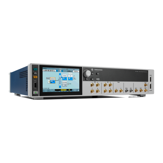
- Page 1 ® R&S SFI100A Wideband IF Vector Signal Generator Getting Started (;ÝÎ>2) 1179641402 Version 03...
- Page 2 ® This document describes the R&S SFI100A, stock no. 1444.4001.02. © 2024 Rohde & Schwarz Muehldorfstr. 15, 81671 Muenchen, Germany Phone: +49 89 41 29 - 0 Email: info@rohde-schwarz.com Internet: www.rohde-schwarz.com Subject to change – data without tolerance limits is not binding. ®...
-
Page 3: Table Of Contents
® Contents R&S SFI100A Contents 1 Safety and regulatory information........5 1.1 Safety instructions................5 1.2 Labels on R&S SFI100A............... 9 1.3 Warning messages in the documentation.......... 9 1.4 Where to find key documents on Rohde & Schwarz....... 10 1.5 Korea certification class A..............10 2 Documentation overview............ - Page 4 ® Contents R&S SFI100A 4.13 Connecting to Ref In/Ref Out.............24 4.14 Switching on or off................24 5 Instrument tour..............26 5.1 Front panel tour.................. 26 5.2 Rear panel tour..................30 6 Trying out the instrument........... 34 6.1 Generating an unmodulated RF signal..........35 6.2 Generating a modulated RF signal............36 6.3 Generating a wideband RF signal.............
-
Page 5: Safety And Regulatory Information
® Safety and regulatory information R&S SFI100A Safety instructions Safety and regulatory information The product documentation helps you use the product safely and efficiently. Fol- low the instructions provided here and in the following sections. Intended use The product generates radio frequency (RF) signals for the development, produc- tion and verification of electronic components, modules or devices. - Page 6 ® Safety and regulatory information R&S SFI100A Safety instructions the instructions provided here and in the product documentation. Keep the prod- uct documentation nearby and offer it to other users. Use the product only for its intended use and within its performance limits. Inten- ded use and limits are described in the product documentation such as the speci- fications document, manuals and the printed "Safety Instructions"...
- Page 7 ® Safety and regulatory information R&S SFI100A Safety instructions Setting up the product Always place the product on a stable, flat and level surface with the bottom of the product facing down. If the product is designed for different positions, secure the product so that it cannot fall over.
- Page 8 ® Safety and regulatory information R&S SFI100A Safety instructions and disconnect it from the power source. How to change the fuse is described in the product documentation. ● Only use the power cable delivered with the product. It complies with country- specific safety requirements.
-
Page 9: Labels On R&S Sfi100A
® Safety and regulatory information R&S SFI100A Warning messages in the documentation Labels on R&S SFI100A Labels on the casing inform about: ● Personal safety, see "Connecting to power" on page 7. ● Product and environment safety, see Table 1-1. ●... -
Page 10: Where To Find Key Documents On Rohde & Schwarz
® Safety and regulatory information R&S SFI100A Korea certification class A Where to find key documents on Rohde & Schwarz Certificates issued to Rohde & Schwarz that are relevant for your country are pro- vided at www.rohde-schwarz.com/key-documents, e.g. concerning: ● Quality management ●... -
Page 11: Documentation Overview
® Documentation overview R&S SFI100A Videos Documentation overview This section provides an overview of the R&S SFI100A user documentation. Unless specified otherwise, you find the documents at: www.rohde-schwarz.com/manual/sfi100a Getting started manual Introduces the R&S SFI100A and describes how to set up and start working with the product. -
Page 12: Key Features
® Key features R&S SFI100A Key features The R&S SFI100A is a wideband IF vector signal generator in the high-end range developed to meet demanding customer requirements for wideband I/Q and RF testing up to the sub-THz frequency range. Offering excellent signal characteris- tics and straightforward and intuitive operation, the R&S SFI100A makes signal generation fast and easy. -
Page 13: Preparing For Use
® Preparing for use R&S SFI100A Choosing the operating site Preparing for use Here, you can find basic information about setting up the product for the first time. Lifting and carrying For safety information, see "Lifting and carrying the product" on page 6. -
Page 14: Setting Up The R&S Sfi100A
® Preparing for use R&S SFI100A Setting up the R&S SFI100A Electromagnetic compatibility classes The electromagnetic compatibility (EMC) class indicates where you can operate the product. The EMC class of the product is given in the specifications docu- ment. ● Class B equipment is suitable for use in: –... - Page 15 ® Preparing for use R&S SFI100A Setting up the R&S SFI100A ● If the products have foldable feet, fold them in completely. ● All products must have the same dimensions (width and length). ● Do not exceed a total load of 50 kg placed on the product at the bottom of the stack.
-
Page 16: Considerations For Test Setup
® Preparing for use R&S SFI100A Considerations for test setup b) Mount the adapter kit. Follow the assembly instructions provided with the adapter kit. 2. Lift the R&S SFI100A to shelf height. 3. Push the R&S SFI100A onto the shelf until the rack brackets fit closely to the rack. -
Page 17: Connecting To Power
® Preparing for use R&S SFI100A Connecting to LAN Signal input and output levels The specifications document provides information on signal levels. Keep the sig- nal levels within the specified ranges to avoid damage to the R&S SFI100A and connected devices. Over-the-air (OTA) tests For over-the-air (OTA) tests, operate the instrument in a shielded environment. -
Page 18: Connecting A Monitor
® Preparing for use R&S SFI100A Connecting a monitor ● When connected to the LAN, the product may potentially be accessed from the internet, which may be a security risk. For example, attackers might mis- use or damage the product. To connect to LAN ►... -
Page 19: Connecting Usb Devices
® Preparing for use R&S SFI100A Connecting USB devices ● VGA: You need an active adapter, Display Port to VGA. Passive adapters do not work. If the monitor provides touch functionality, an additional connection can be required, for example, a USB connection. Refer to the documentation of your monitor. -
Page 20: Establishing The High-Speed Digital Crosslink
® Preparing for use R&S SFI100A Establishing the high-speed digital crosslink To connect a mouse ► Connect the USB storage device to a USB connector on the rear panel. When connected, the R&S SFI100A detects the mouse automatically. To connect power sensors Connect power sensors of the R&S NRP families to a USB connector on the rear panel. - Page 21 ® Preparing for use R&S SFI100A Establishing the high-speed digital crosslink See also (2) and (4) in Figure 4-1. Figure 4-1: QSFP+ connections for I/Q data crosslink 1, 3 = I components crosslink with connectors "Dig. IQ HS 1" and "Dig. IQ HS 3" 2, 4 = Q components crosslink with connectors "Dig.
-
Page 22: Connecting To Rf Coaxial Connectors
® Preparing for use R&S SFI100A Connecting to RF coaxial connectors 1 = QSFP+ plug 2 = QSFP+ cage 3 = QSFP+ connector 4.11 Connecting to RF coaxial connectors Here, you find information on how to prepare and to connect to RF coaxial con- nectors of the R&S SFI100A. - Page 23 ® Preparing for use R&S SFI100A Connecting to RF coaxial connectors To connect to screwable connectors ► NOTICE! Excessive tightening can damage the connectors. To connect the cable with the connector, proceed as follows: a) Carefully align the connector of the cable and the connector along a com- mon axis.
-
Page 24: Connecting To Rf Out
® Preparing for use R&S SFI100A Switching on or off 4.12 Connecting to RF Out 1. Before connecting, disable the RF output: In the block diagram, switch off the RF block. 2. For connection, use the connector "RF Out" on the front panel. "To connect to screwable connectors"... - Page 25 ® Preparing for use R&S SFI100A Switching on or off To switch on the R&S SFI100A The R&S SFI100A is off but connected to power. See Chapter 4.6, "Connecting to power", on page 17. 1. Set the switch on the power supply to position [I] on the rear panel. The LED of the [On/Standby] key on the front panel is orange.
-
Page 26: Instrument Tour
® Instrument tour R&S SFI100A Front panel tour Instrument tour This chapter explains the control elements and the connectors of the R&S SFI100A. The views of the front panel and the rear panel help you to get familiar with the instrument and to perform the first steps. For specifications of the interfaces, see the specifications document. - Page 27 ® Instrument tour R&S SFI100A Front panel tour 5.1.1 Touchscreen The screen on the front panel displays the block diagram and the most important settings. Also, the screen display provides status and setting information and allows you to quickly reconfigure the signal flow. The screen is touch-sensitive, offering an alternative means of user interaction for quick and easy handling of the instrument.
- Page 28 ® Instrument tour R&S SFI100A Front panel tour Table 5-1: Utility keys Utility key Assigned functions [Preset] Sets the instrument to a defined state. [Save/Recall] Opens the file manager to save or load an instrument configuration. Accesses the file manager [Help] Opens the "Help"...
- Page 29 ® Instrument tour R&S SFI100A Front panel tour 5.1.3 Connectors There are SMA connectors, a USB connector and "Sync" connectors on the front panel. Female USB (universal serial bus) 2.0 connector of type A (host USB). You can connect, for example, a keyboard, a mouse or a USB memory stick. How to: Chapter 4.9, "Connecting USB devices",...
-
Page 30: Rear Panel Tour
® Instrument tour R&S SFI100A Rear panel tour Table 5-3 lists available User x connectors and their description. Table 5-3: User x front panel connectors Connector Description User 1 Trigger signal input or output, high-level and low-level control signal output. User 2 Trigger signal input or output, high-level and low-level control signal output. - Page 31 ® Instrument tour R&S SFI100A Rear panel tour AC power supply connector and switch = Serial number (six digits in the string 1444.4001.02-<serial number>-<checksum>) Ref In/Ref Out Display Port 7, 11 = Dig. IQ HS x 8, 12 = IP Data 9, 13 = User x 10, 14 =...
- Page 32 ® Instrument tour R&S SFI100A Rear panel tour RJ-45 connector to connect the R&S SFI100A to a LAN for remote control, remote operation and data transfer. How to: Chapter 4.7, "Connecting to LAN", on page 17 Two female USB (universal serial bus) 3.1 connectors of type A (host USB). They have the same functionality as the USB connector on the front panel, but provide higher data rates.
- Page 33 ® Instrument tour R&S SFI100A Rear panel tour Four BNC multipurpose connectors for future use. How to: "To connect to pluggable connectors" on page 23 Getting Started 1179.6414.02 ─ 03...
-
Page 34: Trying Out The Instrument
® Trying out the instrument R&S SFI100A Trying out the instrument This chapter provides step-by-step instructions to introduce the most important functions and settings of the R&S SFI100A. Prerequisites ● The R&S SFI100A is equipped with its base unit configuration. ●... -
Page 35: Generating An Unmodulated Rf Signal
® Trying out the instrument R&S SFI100A Generating an unmodulated RF signal Generating an unmodulated RF signal This step-by-step instruction explains how to generate an unmodulated RF con- tinuous wave signal. This signal is an IF signal in the frequency range of 11 GHz to 21 GHz. -
Page 36: Generating A Modulated Rf Signal
® Trying out the instrument R&S SFI100A Generating a modulated RF signal Generating a modulated RF signal This step-by-step instruction explains how to generate a modulated RF signal. This signal is an IF signal in the frequency range of 11 GHz to 21 GHz. The signal is sufficient for generic IF receiver testing, for example for testing chipsets. - Page 37 ® Trying out the instrument R&S SFI100A Generating a modulated RF signal The dialog provides detailed information on the waveform file including the file size and the clock frequency. 5. Select "State" > "On". The R&S SFI100A loads the waveform file and starts signal processing. 6.
-
Page 38: Generating A Wideband Rf Signal
® Trying out the instrument R&S SFI100A Generating a wideband RF signal 7. In the block diagram, select "RF" > "On" to enable IF signal generation. The R&S SFI100A outputs this IF signal at the "RF Out" connector on the front panel. - Page 39 ® Trying out the instrument R&S SFI100A Generating a wideband RF signal To connect an external frontend This step-by-step instruction describes how to connect the R&S SFI100A to an R&S FE170ST. The instruments are switched on and connected to power. 1.
- Page 40 ® Trying out the instrument R&S SFI100A Generating a wideband RF signal Table 6-1: R&S SFI100A and R&S FE170ST connections Signal R&S SFI100A R&S FE170ST Reference Connector: "Ref Out 2" "Ref In" Frequency: 1 GHz, 8 GHz LAN (Control) "LAN" "LAN"...
- Page 41 ® Trying out the instrument R&S SFI100A Generating a wideband RF signal A message displays if the remote connection to the external frontend is estab- lished or not. Figure 6-2: Message displaying an established remote connection If connected successfully, you can configure dedicated frontend settings in the "Frontend Configuration"...
- Page 42 ® Trying out the instrument R&S SFI100A Generating a wideband RF signal The dialog displays the settings and state of the connected external instru- ment. The "RF" > "Rem Conn" field displays an active control connection: The control connection is established, the LAN LED on the external frontend switches from green to orange.
- Page 43 ® Trying out the instrument R&S SFI100A Generating a wideband RF signal 3. In the block diagram, select "RF" > "On". The RF signal is output at the external frontend. Getting Started 1179.6414.02 ─ 03...
-
Page 44: Operating The Instrument
® Operating the instrument R&S SFI100A Means of manual interaction Operating the instrument This chapter provides an overview on basic operating tasks. There are three ways to operate the R&S SFI100A. Manual operation Use the touchscreen, keys and rotary knobs, or an optional mouse and/or key- board. -
Page 45: Understanding The Display Information
® Operating the instrument R&S SFI100A Understanding the display information Touchscreen operation is the most direct way to interact. Almost all control elements and actions on the screen are based on the standard operating sys- tem concept. You can tap any user interface element to set parameters in dia- log boxes, enter data, scroll within a dialog etc., as if you work with a mouse pointer. - Page 46 ® Operating the instrument R&S SFI100A Understanding the display information Figure 7-1: Block diagram 1 = Status bar 2 = Block diagram 3 = Taskbar ● Status bar......................46 ● Block diagram....................47 ● Taskbar......................48 ● Additional display characteristics..............49 7.2.1 Status bar The status bar at the top of the screen indicates the RF frequency and the level of the output signal provided to the DUT.
- Page 47 ® Operating the instrument R&S SFI100A Understanding the display information The status buttons indicate key parameters that are set for the output signal. Most of the status buttons are virtual keys that you can use to open a corresponding menu or dialog. 7.2.2 Block diagram The block diagram shows the current configuration and the signal flow in the gen-...
- Page 48 ® Operating the instrument R&S SFI100A Understanding the display information Legend Item Description Control signal Indicates information on the control signals like signal content, block input or output and provides quick access to the corresponding configuration dialog. A dedicated control block is displayed to the left of the baseband block.
- Page 49 ® Operating the instrument R&S SFI100A Understanding the display information 1 = System configuration and setup 2 = Remote control connections 3 = Graphics 4 = Dialogs 5 = Show block diagram / more System Config Provides access to general system configurations like setup, display, or remote.
- Page 50 ® Operating the instrument R&S SFI100A Understanding the display information The "Info line" shows brief status information and error messages. It appears when an event generates a message. If selected, the R&S SFI100A shows information on static errors and the error history. ●...
-
Page 51: Accessing The Functionality
® Operating the instrument R&S SFI100A Accessing the functionality Accessing the functionality All functionalities are provided in dialog boxes as known from computer pro- grams. You can control the instrument intuitively with the touchscreen. This sec- tion provides an overview of the accessing methods. The instrument's functions and settings can be accessed by selecting one of the following elements: ●... -
Page 52: Entering Data
® Operating the instrument R&S SFI100A Entering data ● Select the required block, and then the menu entry. ● Select the minimized view (thumbnail) on the taskbar. Some of the utility keys access a dedicated dialog, too. To minimize a dialog box ►... - Page 53 ® Operating the instrument R&S SFI100A Entering data To enter numeric values with the on-screen keypad For numeric settings, the instrument displays the numeric keypad. The units specified correspond to the units of the parameter. 1. Enter the numeric value. Tip: For a quick entry, you can enter a value in an exponential representation, for example 1e7 for 10000000.
-
Page 54: Undo And Redo Actions
® Operating the instrument R&S SFI100A Getting information and help Undo and redo actions Accessed via the context-sensitive menus, "Undo" allows you to restore one or more actions on the instrument. Depending on the available memory, the "Undo" steps can restore all actions. "Redo"... - Page 55 ® Operating the instrument R&S SFI100A Getting information and help Contents of the help dialog box The help dialog box covers two main areas: ● "Contents" - contains a table of help contents ● "Topic" - contains a specific help topic The help system also provides an "Index"...
- Page 56 ® Operating the instrument R&S SFI100A Getting information and help 4. To return to the previous page, select "Back". This function scrolls back all steps that you have performed before. 5. Use the "scroll bars" to shift the visible section of content shown. 6.
-
Page 57: Contacting Customer Support
® Contacting customer support R&S SFI100A Contacting customer support Technical support – where and when you need it For quick, expert help with any Rohde & Schwarz product, contact our customer support center. A team of highly qualified engineers provides support and works with you to find a solution to your query on any aspect of the operation, program- ming or applications of Rohde &... -
Page 58: Index
® Index R&S SFI100A Index User x ..........32 X x ............33 Active elements ........49 Context-sensitive menu ......49 Alphanumeric values Customer support ........57 Entering ..........53 Data entry ..........52 Bench top, placing ........14 Dialog boxes ..........51 Block diagram Display Display .......... - Page 59 ® Index R&S SFI100A Info line ............ 49 On-screen keypad ........49 Input connectors Operating LO In ........... 29 Concepts ..........44 Instrument Operating site Carrying ..........13 Choosing ..........13 Checking ..........13 Setting up the instrument ....14 Lifting ..........13 Operation Operating site .......
- Page 60 ® Index R&S SFI100A Tooltips Show ........... 54 Touchscreen Compared with mouse ......44 Overview ..........27 Usage ..........44 Unpacking the instrument ......13 Utility keys Details - see user manual ....27 Overview ..........27 Videos ............11 VNC ............44 Web interface ..........
Need help?
Do you have a question about the R&S SFI100A and is the answer not in the manual?
Questions and answers