Sign In
Upload
Manuals
Brands
Rohde & Schwarz Manuals
Inverter
SMW200A
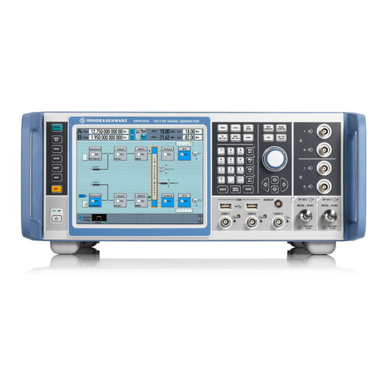
User Manuals: Rohde & Schwarz SMW200A Signal Generator
Manuals and User Guides for Rohde & Schwarz SMW200A Signal Generator. We have
4
Rohde & Schwarz SMW200A Signal Generator manuals available for free PDF download: User Manual
Rohde & Schwarz SMW200A User Manual (1484 pages)
Vector Signal Generator
Brand:
Rohde & Schwarz
| Category:
Portable Generator
| Size: 46 MB
Table of Contents
Table of Contents
3
Safety Instructions
19
Safety and Regulatory Information
19
Labels on R&S SMW200A
22
Warning Messages in the Documentation
22
Where to Find Key Documents on Rohde & Schwarz
23
Korea Certification Class B
23
Welcome to the R&S SMW200A
24
Key Features
24
What's New
24
Documentation Overview
25
Getting Started Manual
25
User Manuals and Help
25
Tutorials
25
Calibration Certificate
26
Release Notes and Open Source Acknowledgment
26
Service Manual
26
Specifications and Product Brochures
26
Printed Safety Instructions
26
Instrument Security Procedures
26
Application Notes, Application Cards, White Papers, Etc
27
Videos
27
Scope and Content
27
Getting Started
29
Preparing for Use
29
Lifting and Carrying
29
Unpacking and Checking
29
Choosing the Operating Site
29
Setting up the R&S SMW200A
30
Considerations for Test Setup
32
Connecting to Power
33
Connecting to LAN
33
Connecting USB Devices
34
Connecting to RF Coaxial Connectors
35
Connecting to RF A/RF B
36
Connecting to lo In/Out
36
Connecting to REF IN/REF out
37
Connecting to HS DIG I/Q
37
Switching on or off
38
Instrument Tour
39
Front Panel Tour
39
Navigation Controls
43
Rotary Knob
43
Navigation Keys
44
Display Keys
44
Rear Panel Tour
46
Generating an Unmodulated Carrier
54
Trying out the Instrument
54
Generating a Digitally Modulated Signal
57
Triggering the Instrument Externally
59
Working with Marker Signals
65
Routing a Baseband Signal to the Outputs
66
Verifying the Generated Signal
71
Saving and Recalling Settings
73
Generating an EUTRA/LTE Signal
75
Enabling MIMO Configuration
78
System Overview
83
Brief Concept of the Instrument
83
Applications Examples of the R&S SMW200A
88
Instrument Control
92
Possible Ways to Operate the Instrument
92
Means of Manual Interaction
93
Understanding the Display Information
94
Block Diagram
95
Additional Display Characteristics
97
Accessing the Functionality
99
Entering Data
100
Getting Information and Help
102
Remote Control
107
Remote Operation over VNC
107
Configuring the System for Your Test Case
108
Signal Routing and System Configuration
108
Working with the System Configuration Function
108
Test Scenario and Required System Configuration
109
Possible Ways to Configure the Signal Flow
113
Using the Signal Routing Settings and the Block Diagram
113
Using the System Configuration Capabilities
114
Overview of the Signals and Interfaces
116
Physical Location of the Input and Output Interfaces
117
Overview of the Baseband Signal Sources
119
Overview of the Baseband and RF Output Signals
120
Important Signal Parameters and Interface Characteristics
121
Supported Digital Interfaces and System Configuration
121
System Configuration Settings
126
Fading and Baseband Configuration Settings
127
I/Q Stream Mapper Settings
135
External RF and I/Q Settings
137
Settings
139
Connector Name
140
Preset Behavior: Keep Connections to External Instruments
140
Direction
141
External Instrument
142
I/Q Connection
142
External Instrument Configuration Settings
145
Settings
146
Clean Unused/Clean All
147
External Instrument
147
Scan
147
Remote Channel
148
Set Symbolic Name
148
Device ID
149
Hostname or IP Address
149
I/Q Output Type
149
Frontend Configuration
150
Initialization Sequence
150
Connections Settings
154
Overview
155
Signal Routing Settings
157
Digital Baseband Input Settings
161
Baseband Input Settings in the Standard Baseband Generator
162
Baseband Input Settings in the Wideband Baseband Generator
169
I/Q Digital Output Settings
175
General Settings
178
Channels Settings
181
Signal Output Settings
183
I/Q Analog Output Settings
186
General Analog I/Q Output Settings
189
I/Q Output Type
190
RF Envelope
190
I/Q Level Vp (EMF)
191
Bias (EMF)
192
Couple I/Q Bias
192
Offset (EMF)
192
How to Connect External Instruments and Configure the Signal Flow
193
Finding out the Suitable Configuration for Your Test Situation
194
How to Find out Where the Input/Output Interface Is Located
195
How to Define the MIMO Scenario
196
How to Route the I/Q Streams to the Output Interfaces
198
How to Cable the Instruments in MIMO Test Setups
199
How to Connect and Configure External Instruments
200
Connecting to HS DIG I/Q Interfaces
209
How to Generate a 2X8 MIMO Signal for BS Tests
214
How to Generate a 8X8 MIMO Signal with Two R&S SMW200A
216
How to Connect an R&S ® CMW500 for Fading Applications
220
How to Apply an External Digital Baseband Signal
221
How to Connect an R&S EX-IQ-BOX
224
Configuring the Internal Baseband Source
226
Overview of the Signal Generation Modes
226
Standard or Wideband Baseband Generator
227
Accessing the Functions in the Baseband Domain
229
Generating Signals According to Digital Standards
230
About Common Baseband Characteristics
234
Marker Modes
242
Common Characteristics of the Baseband Domain
234
Common Baseband Settings
261
Triggering with a Common Signal
271
Time-Based Triggering
273
Generating Custom Digital Modulation Signals
276
About Custom Digital Modulation
277
Custom Digital Modulation Settings
277
Required Options
277
How to Create Data and Control Lists
299
References
303
Common Coding Algorithms
307
Using the Arbitrary Waveform Generator (ARB)
314
About ARB
315
Required Options
315
ARB Settings
321
Advertisement
Rohde & Schwarz SMW200A User Manual (1403 pages)
Vector Signal Generator
Brand:
Rohde & Schwarz
| Category:
Laboratory Equipment
| Size: 42 MB
Table of Contents
Table of Contents
3
Safety and Regulatory Information
19
Safety Instructions
19
Labels on R&S SMW
21
Korea Certification Class B
22
Warning Messages in the Documentation
22
Documentation Overview
23
Key Features
23
Welcome
23
Getting Started Manual
24
Instrument Security Procedures
24
Service Manual
24
Tutorials
24
User Manuals and Help
24
Application Notes, Application Cards, White Papers, Etc
25
Data Sheets and Brochures
25
Printed Safety Instructions
25
Release Notes and Open Source Acknowledgment (OSA)
25
Scope and Content
25
Choosing the Operating Site
27
Getting Started
27
Lifting and Carrying
27
Preparing for Use
27
Unpacking and Checking
27
Setting up the R&S SMW
28
Considerations for Test Setup
30
Connecting to LAN
31
Connecting to Power
31
Connecting USB Devices
32
Connecting to RF A/RF B
33
Connecting to HS DIG I/Q
35
Connecting to lo In/Out
35
Connecting to REF IN/REF out
35
Switching on or off
36
Front Panel Tour
37
Instrument Tour
37
Rear Panel Tour
44
Trying out the Instrument
52
Generating an Unmodulated Carrier
53
Generating a Digitally Modulated Signal
55
Triggering the Instrument with an External Signal
57
Enabling and Configuring a Marker Signal
63
Routing a Baseband Signal to the Outputs
64
Verifying the Generated Signal
69
Saving and Recalling Settings
71
Generating an EUTRA/LTE Signal
73
Enabling MIMO Configuration
76
Brief Introduction to the Instrument's Concept
81
System Overview
81
Applications Examples of the R&S SMW
86
Instrument Control
90
Possible Ways to Operate the Instrument
90
Means of Manual Interaction
91
Understanding the Display Information
92
Accessing the Functionality
97
Entering Data
98
Getting Information and Help
100
Remote Control
105
Remote Operation over VNC
105
Finding out the System Configuration for a Current Test Case
106
How the System Configuration Function Supports You in Your Task
106
Signal Routing and System Configuration
106
From a Test Scenario to the Required System Configuration
108
Possible Ways to Configure the Signal Flow
110
Using the Signal Routing Settings and the Block Diagram
110
Using the System Configuration Capabilities
111
Overview of the Input and Output Signals and Interfaces
113
Physical Location of the Input and Output Interfaces
114
Overview of the Baseband Signal Sources
116
Overview of the Baseband and RF Output Signals
118
Important Signal Parameters and Interface's Characteristics
119
Supported Digital Interfaces Depending on the System Configuration
119
System Configuration Settings
124
Fading and Baseband Configuration Settings
125
Settings: Mode
126
Signal Outputs
127
Entities (Users, Cells)
128
Signal Routing
128
System Configuration Lxmxn
128
BB Signals (Tx Antennas)
129
Streams (Rx Antennas)
129
Subset
129
Baseband Source Config
130
BB Bandwidth
130
CA Bandwidth
130
Duplicate Streams
131
HS Channels Per
131
Apply
132
I/Q Stream Mapper Settings
132
Set to Default
132
Mode
133
External RF and I/Q Settings
135
Settings: Display/Auto Connect
137
Auto Connect
137
Connect/Disconnect All Remote
137
Settings: Display
137
Connector Name
138
Preset Behavior: Keep Connections to External Instruments
138
Direction
139
External Instrument
140
I/Q Connection
140
Remote Connection Status
141
(Delta) RF Frequency/ RF Level
142
Instrument Name
142
RF Couple
142
RF State
143
Overview
152
Signal Routing Settings
154
Chapter 4 Digital Baseband Input Settings
158
Baseband Input Settings in the Standard Baseband Generator
159
Baseband Input Settings in the Wideband Baseband Generator
166
I/Q Digital Output Settings
172
General Settings
175
Channels Settings
178
Signal Output Settings
179
I/Q Analog Output Settings
182
General Analog I/Q Output Settings
184
RF Envelope
185
Save/Recall
185
Set to Default
185
State
185
I/Q Output Type
186
Mode
186
Show Connector
186
I/Q Level Vp EMF
187
How to Connect External Instruments and Configure the Signal Flow
188
Finding out the Suitable Configuration for Your Test Situation
189
How to Find out Where the Input/Output Interface Is Located
190
Interfaces
190
Scenario
190
Setups
190
How to Define the MIMO Scenario
191
How to Route the I/Q Streams to the Output Interfaces
193
How to Cable the Instruments in MIMO Test Setups
194
How to Connect and Configure External Instruments
195
Instruments
195
How to Generate a 2X8 MIMO Signal for BS Tests
204
How to Generate a 8X8 MIMO Signal with Two R&S SMW
206
R&SCMW500 for Fading Applications
210
How to Apply an External Digital Baseband Signal
211
Signal
211
Ex-Iq-Box
214
How to Connect an R&S EX-IQ-BOX
214
Configuring the Internal Baseband Source
216
Overview of the Signal Generation Modes
216
Standard or Wideband Baseband Generator
217
Accessing the Functions in the Baseband Domain
219
Generating Signals According to Digital Standards
220
Common Functions and Settings in the Baseband Domain
224
Basics on Signals, Modulation Types and Filters Used the Baseband Domain
224
Data, Clock and Control Signals and Sources in the Baseband
224
Regular Marker Output Signals
231
Baseband Trigger Signals
235
Supported Modulation Signals
245
Supported Coding Schemes
246
Supported Baseband Filters
247
Methods for Optimizing the Crest Factor
249
Common Settings
251
How to Use the Trigger Settings
259
Generating Custom Digital Modulated Signals
261
About the Custom Digital Modulation
262
Custom Digital Modulation Settings
262
Required Options
262
Settings: General Settings 263 ●
263
Settings: General Settings
263
Save/Recall
264
Set to Default
264
Settings: State
264
Standard
264
Setting
265
Data Source
266
Modulation Settings
271
Filter Settings
274
Power Ramp Control Settings
276
Data List Editor
279
Control and Marker Lists Editor
281
Select "Baseband > Custom Digital Mod
281
How to Create Data and Control Lists
285
References
288
Required Options
296
Using the Arbitrary Waveform Generator (ARB)
296
About ARB
297
ARB Settings
301
Settings
303
State
303
Set to Default
304
Use One Waveform for All Basebands
304
Load Waveform/File
305
Waveform Info
305
Waveforms Table
305
Clock Frequency
306
Create Multi Carrier
306
Create Multi Segment
306
Delay
306
RF Power Ramping with Burst Marker
306
Test Signal Form
306
Create Test Signal
307
How to Create, Generate and Play Waveform Files
311
Tags for Waveforms, Data and Control Lists
327
Example: {Clock: 54000000} Bb:arb:wav:tag? 'Clock'
331
CLOCK: Frequency
331
CONTROL LENGTH: Controllength
332
EMPTYTAG-Length: #Emptysequence
332
LEVEL OFFS: Rmsoffset_Db,Peakoffset_Db
333
Marker Mode [#]: Generator
334
BURST LIST [#]: Pos0:State0; Pos1:State1
335
CW MODE LIST [#]: Pos0:State0; Pos1:State1
335
HOP LIST [#]: Pos0:State0; Pos1:State1
335
LEVATT LIST [#]: Pos0:State0; Pos1:State1
335
MAP LIST [#]: Pos0:State0; Pos1:State1
335
MARKER LIST [#]: Pos0:State0; Pos1:State1
335
SAMPLES: Samples
335
[TRACE] LIST [#]: Pos0:State0; Pos1:State1
335
WAVEFORM-Length: #I0Q0I1Q1
336
MWV_SEGMENT_COUNT: Numofseg
337
MWV_SEGMENT_CLOCK_MODE: Mode
338
MWV_SEGMENT_DURATION: Segdur0, Segdur1
338
MWV_SEGMENT_LENGTH: Samplesseg0, Samplesseg1
338
Mwv_Segment_Start
338
Samplestartoffsetseg0, Samplestartoffsetseg1
338
MWV_SEGMENT_CLOCK: Clockseg0, Clockseg1
339
MWV_SEGMENT_LEVEL_MODE: Mode
339
Filenameseg0.Wv", "Filenameseg1.Wv
340
Mwv_Segment_Files
340
Mwv_Segment_Level_Offs
340
MWV_SEGMENT_SETTINGS_FILE: Segsettingfilepath
340
Rmsoffs_Dbsg0,Peakoffs_Dbsg0
340
CONTROL LIST WIDTH4-Length: #M0M1
341
Mwv_Segmentx_Comment: Text
341
About the Notch Filters
345
Generating Notched Signals
345
Required Options
345
Notch Filter Settings
346
AWGN Test Signal
349
Generating Multi-Segment Waveform Files
351
Reducing the Crest Factor
351
About the Multi-Segment Waveforms
352
Required Options
352
Multi-Segment Settings
357
Settings
359
Setting for Handling the Multi-Segment Files and Output File Settings
359
Segment Table
361
Level / Clock / Marker Settings
363
Sequencing
365
Next Segment Trigger in Settings
369
Settings
370
Current Segment/Current Segment Index
370
Segment
370
Next Segment Mode
371
Execute Next Segment
372
Level Mode
372
Next Segment Source
372
Sequencing List
372
How to Create and Work with Multi-Segment Waveform Files
373
Trigger Example
373
Reference to Triggering of Multi-Segment Waveforms
378
Generating Multi-Carrier Signals
381
About the Multi-Carrier Waveforms
382
Required Options
382
Multi-Carrier Settings
384
Rohde & Schwarz SMW200A User Manual (1312 pages)
Vector Signal
Brand:
Rohde & Schwarz
| Category:
Inverter
| Size: 44 MB
Table of Contents
Table of Contents
18
Customer Support
17
1 Preface
42
About this Manual
43
Documentation Overview
45
Instrument Security Procedures
46
Overview of the Instrument Functions and the Related Description
47
Wideband Baseband Generator Related Settings and Descriptions
49
Getting Started
51
EMI Suppression
52
Accessory List
53
Connecting AC Power
55
Functional Check
57
Checking the Supplied Options and Licenses
58
Connecting USB Devices
59
Setting up a Network (LAN) Connection
60
Using Computer Names (Hostnames)
61
Assigning the IP Address
63
Configuring the Initial Instrument Settings
64
Setting the Keyboard Language
65
Adjusting Appearance of the User Interface
66
Instrument Tour
67
Touchscreen
68
Keys
70
Function Keys
71
Navigation Controls
72
Connectors
73
Rear Panel Tour
75
Connectors
77
Trying out the Instrument
81
Generating an Unmodulated Carrier
82
Generating a Digitally Modulated Signal
84
Triggering the Instrument with an External Signal
86
Enabling and Configuring a Marker Signal
92
Routing the Signal through the Instrument and Defining the Output Connectors
93
Verifying the Generated Signal with the Graphics Display
98
Saving and Recalling Settings
101
Generating an EUTRA/LTE Signal
104
Using the System Configuration Capabilities for MIMO Setups
107
System Overview
112
Internal Baseband Source ("Baseband" Blocks)
115
Fading Simulator ("Fading" Blocks)
116
I/Q Modulator ("I/Q Mod" Blocks)
117
Transmit Diversity Test (MISO Scenario)
118
Generation of Signals for Testing of WCDMA Handover (Two Cells)
119
Generation of an LTE Test Signal with Carrier Aggregation and 2X2 MIMO each Com Ponent Carrier
120
2.5 Instrument Control
121
Generation of a WLAN 802.11Ad Signal with 1.76 Ghz Bandwidth
121
Instrument Control
122
2.5.2 Means of Manual Interaction
122
2.5.3 Understanding the Display Information
123
Possible Ways to Operate the Instrument
121
Block Diagram
124
Taskbar
125
Additional Display Characteristics
126
2.5.4 Accessing the Functionality
128
2.5.5 Entering Data
129
Entering Numeric Parameters
130
2.5.6 Getting Information and Help
131
Using the Tutorials
133
2.5.7 Remote Control
136
2.5.8 Remote Operation over VNC
136
From a Test Scenario to the Required System Configuration
139
Possible Ways to Configure the Signal Flow
141
Using the System Configuration Capabilities
142
Overview of the Input and Output Signals and Interfaces
144
Physical Location of the Input and Output Interfaces
145
Overview of the Baseband Signal Sources
147
Overview of the Baseband and RF Output Signals
148
3 Signal Routing and System Configuration
137
Specific Characteristics of the Digital I/Q Interface
150
Specifics of the Analog I/Q Interfaces
152
Fading and Baseband Configuration Settings
153
Table of Contents
154
Mode
155
Set to Default
155
Signal Outputs
155
Signal Routing
156
System Configuration Lxmxn
156
Entities (Users, Cells)
156
BB Signals (Tx Antennas)
157
I/Q Stream Mapper Settings
159
External RF and I/Q Settings
162
Connections Configuration and Connection Status Overview Settings
163
Sconfiguration:external:display
164
Auto Connect
164
Connect/Disconnect All Remote
164
Settings: Display
164
Connector Name
165
Preset Behavior: Keep Connections to External Instruments
165
Direction
166
External Instrument
167
I/Q Connection
167
Remote Connection Status
167
Instrument Name
168
RF Couple
168
(Delta) RF Frequency/ RF Level
169
External Instrument Configuration Settings
169
Remote Config Settings
170
Initialization Sequence Settings
174
Remote Control Settings
176
Show Connector
177
Check Connections Settings
178
RF State
169
Overview
179
Signal Routing Settings
181
Digital Baseband Input Settings
185
General Settings
187
Sample Rate Settings
188
Input Level Settings
190
Signal Monitoring Settings
191
I/Q Digital Output Settings
193
General Settings
195
Signal Output Settings
197
I/Q Analog Output Settings
200
3.8.1 General Analog I/Q Output Settings
202
Set to Default
202
General Analog I/Q Output Settings
202
Settings: State
202
I/Q Output Type
203
RF Envelope
203
Save/Recall
203
Bias (EMF)
204
Couple I/Q Bias
204
I/Q Level Vp EMF
204
Mode
204
Offset (EMF)
205
How to Connect External Instruments and Configure the Signal Flow
206
Finding out the Suitable Configuration for Your Test Situation
207
How to Define the MIMO Scenario
208
How to Route the I/Q Streams to the Output Interfaces
211
How to Cable the Instruments in MIMO Test Setups
212
How to Connect and Configure External Instruments
213
How to Generate a 2X8 MIMO Signal for BS Tests
222
How to Generate a 8X8 MIMO Signal with Two R&S SMW
224
How to Apply an External Digital Baseband Signal
230
How to Connect an R&S EX-IQ-BOX
233
4 Configuring the Internal Baseband Source
235
Standard or Wideband Baseband Generator
236
How to Access the Functions in the Baseband Domain
238
Generating Signals According to Digital Standards
239
Common Functions and Settings in the Baseband Domain
242
Internal Modulation Data
243
External Modulation Data
244
Clock Signals
245
Control Signals
247
Regular Marker Output Signals
249
Marker Modes
250
Marker Minimum Duration
251
Delaying Marker Signals
252
Trigger Sources
253
Impact of the Trigger Modes on the Signal Generation
254
Impact of the Additional Trigger Settings
256
Receiving and Providing Trigger Signals
259
Supported Modulation Types
262
Supported Coding Schemes
263
Impact of the Filter Parameters
264
Methods for Optimizing the Crest Factor
265
Common Settings
267
Trigger Settings
268
Marker Settings
273
Clock Settings
275
Local and Global Connector Settings
276
Trigger the Baseband Sources with a Common Signal
277
Generating Custom Digital Modulated Signals
279
4.6.3 Custom Digital Modulation Settings
280
Custom Digital Modulation Settings
280
Settings: General Settings
280
Data Source
283
Trigger, Marker and Clock Setting
283
Modulation Settings
288
Filter Settings
291
Power Ramp Control Settings
292
Data List Editor
295
Control and Marker Lists Editor
297
How to Create Data and Control Lists
300
How to Create and Assign a Control List
301
How to Create and Assign a Data List
303
References
304
Predefined Modulation Types
307
Common Coding Algorithms
310
Predefined Baseband Filters
312
Using the Arbitrary Waveform Generator (ARB)
315
About the ARB
316
Waveform Sample Rate
318
Impact on the Enabled Number of Marker Signals on the Waveform Length
319
ARB Settings
320
Settings: State
322
Load Waveform/File
323
Set to Default
323
Use One Waveform for All Basebands
323
Waveforms Table
323
Clock Frequency
324
Create Multi Segment
324
Delay
324
Waveform Info
324
Create Multi Carrier
325
Create Test Signal
325
Sine Test Signals
326
Rectangular Test Signal
327
Constant IQ Test Signal
329
Trigger, Marker and Clock Setting
330
How to Generate and Play Waveform Files
331
How to Load and Play Waveform Files
332
How to Create a Waveform File Generated with the R&S Winiqsim2 and Load It in the ARB
333
References
339
Multi-Segment Waveforms Processing
340
File Concept
341
Impact of the Trigger Settings and Next Segment Settings
342
Multi-Segment Settings
345
Setting for Handling the Multi-Segment Files and Output File Settings
346
Segment Table
348
Level / Clock / Marker Settings
350
Multi-Segment Waveform Sequencing
352
General Settings
354
Sequencing Play List Settings
355
Next Segment Trigger in Settings
357
How to Create and Work with the Multi-Segment Waveform Files
360
Reference to Triggering of Multi-Segment Waveforms
366
Triggering in "Next Trigger Mode = Next Segment
367
Triggering in "Next Trigger Mode = Next Segment Seamless
368
Triggering in "Next Trigger Mode = Sequencer
369
Required Options
370
Defining the Carrier Frequency
371
Multi-Carrier Settings
372
Set to Default
373
Mode
374
Number of Carriers
374
Save/Recall Frame
374
Carrier Spacing
375
Clipping
375
Crest Factor Mode
375
Frequency
375
Target Crest Factor
375
Power Reference
376
Signal Period
376
Signal Period Mode
376
Output Settings
378
File
379
Clock Rate
379
File Size
379
Create/Create and Load
379
Carrier Table Settings
380
Carrier Table Assistant
382
Carrier Graph
384
How to Use the Multi-Carrier Function
385
Generating Multi-Carrier Continuous Wave Signal
387
Required Options
388
General Carrier Settings
389
Carrier Table
391
Carrier Graph
394
How to Use the Multi-Carrier Continuous Wave Function
395
References
396
Generating a Linear Slope Ramp Waveform
397
About the Baseband Offsets
398
Impact of the Phase Offset
399
Impact of the Gain
400
How to Improve Signal Characteristics by Shifting the Wanted Baseband Signal
402
Simulating Fading, Adding Noise and Predistortions, and Impairing the Signal
404
About the AWGN Generator
405
AWGN Settings
409
General Settings
411
Noise Power/Output Results Settings
413
Connected Instrument
414
Reference Mode
414
Set Noise Power Via
414
Show Powers for Output
414
Bit Rate
415
Carrier/Noise Ratio, Signal/Noise Ratio
415
E B /N
415
Carrier Power, Signal Power
416
Noise Power (System Bandwidth), Interferer Power
416
Noise Power (Total Bandwidth)
417
How to Configure the Noise Generator for Receiver Tests
418
Impairing the Signal
421
Gain and Gain Imbalance
422
I and Q Offset
423
Analog and Digital Impairments Settings
424
How to Optimize the Carrier Leakage and Sidebands Suppression
428
Frequency Response Correction
429
I/Q Modulator Settings
431
6 Applying I/Q Vector Modulation
430
Settings: Source/State
433
Settings: Source
433
State
433
Adjust I/Q Modulator Current Frequency
434
I/Q Swap
434
(Baseband) Gain
435
Crest Factor
435
I/Q Wideband
435
Linearize RF
436
Optimization Mode
436
Adjust Linearization Current Frequency
437
Frequency Response Settings
437
How to Adjust the I/Q Modulator to Optimize Performance
439
How to Access the Functions in the RF Domain
442
7 Configuring the Signal in the RF Domain
441
Required Options
444
Configuring RF Frequency and Level
445
RF Level Settings
449
Advertisement
Rohde & Schwarz SMW200A User Manual (37 pages)
ERA-GLONASS Test Suite
Brand:
Rohde & Schwarz
| Category:
Test Equipment
| Size: 2 MB
Table of Contents
Table of Contents
3
Key Features
5
Prerequisites
7
Test Setup
9
System Configuration
10
Preparation of Controller PC
10
Preparation of Instrument Connection
10
Preparation of IVS Connection
11
Test Configuration
16
Connection Setting
17
Vehicle Simulation Setting
17
GNSS Simulation Setting
19
Signal Power Setting
20
Test Case Setting
21
Advanced Settings
26
Thresholds
27
Miscellaneous
27
Exclude Acceleration Interval
28
GNSS Signal Logging
28
Ignore Coordinate System
28
Log Exclude Acceleration Interval
28
Smx/Ivs Configuration
28
GNSS Signal Logging Rate
29
TC 5.5 Receiver Autonomous Integrity Monitoring (RAIM)
29
TC 5.8 Error Estimation / TC 5.10 Restore Interval
29
TC 5.12 Sensitivity
29
TC 5.14 Cut off Angle
29
Test Results
30
Monitoring
35
Test Module Details
37
Advertisement
Related Products
Rohde & Schwarz SMB100A
Rohde & Schwarz SMF100A
Rohde & Schwarz SMF-B1
Rohde & Schwarz SMF-B131
Rohde & Schwarz SMF-K27
Rohde & Schwarz SMF-K28
Rohde & Schwarz SMR40
Rohde & Schwarz SMCV100B
Rohde & Schwarz R&S SMC-B101
Rohde & Schwarz SMATE200A
Rohde & Schwarz Categories
Measuring Instruments
Test Equipment
Portable Generator
Power Supply
Accessories
More Rohde & Schwarz Manuals
Login
Sign In
OR
Sign in with Facebook
Sign in with Google
Upload manual
Upload from disk
Upload from URL