Table of Contents
Advertisement
Quick Links
Printed in the Federal
Republic of Germany
1104.3430.82
www.valuetronics.com
Service Manual Instrument
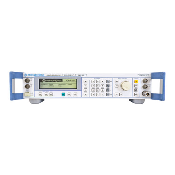
MIKROWELLEN-SIGNALGENERATOR
R&S SMR20
1104.0002.20
R&S SMR27
1104.0002.27
R&S SMR30
1104.0002.30
R&S SMR40
1104.0002.40
R&S SMR50
1104.0002.50
R&S SMR60
1104.0002.60
Test and Measurement
Division
1
E-2
Advertisement
Table of Contents


Need help?
Do you have a question about the R&S SMR20 and is the answer not in the manual?
Questions and answers