Table of Contents
Advertisement
Quick Links
Advertisement
Table of Contents

Related Manuals for Mizuho 7200B


Summary of Contents for Mizuho 7200B
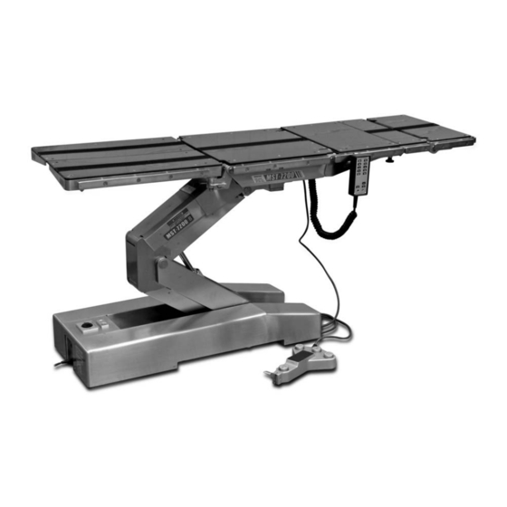
- Page 1 SURGICAL TABLES MODEL 7200B OPERATORS MANUAL 10-04...
-
Page 3: Table Of Contents
TABLE OF CONTENTS Title Page SPECIAL USER ATTENTION ........................ 2 SECTION I INTRODUCTION ......................... 5 1-1. General ............................5 1-2. Power Requirements ........................5 1-3. Pendant Control Unit ........................6 1-4. Foot Control Unit .......................... 6 SECTION II OPERATION ........................7 2-1. -
Page 4: Special User Attention
SPECIAL USER ATTENTION The extreme positioning capabilities of the 7200 WARNING Series Table requires special attention for possible interference points when using multiple function Prior to operating the table, observe positioning. As with the operation of any surgical all table caution labels and review the table, a certain amount of care should be exercised SPECIAL USER ATTENTION sec- to position the patient safely. - Page 5 SPECIAL USER ATTENTION WARNING WARNING To maximize patient safety, utilize Potential pinch and/or crush hazard proper restraint methods during ex- exists if hands or fingers are placed treme Trendelenburg positioning between the edges of seat and leg modes. sections when leg sections are raised or lowered.
- Page 6 SPECIAL USER ATTENTION WARNING Always follow OSHA blood-borne patho- gens standards for protective clothing, including gloves, masks and eye pro- tection when cleaning the surgical table. CAUTION Thoroughly read and follow the manufacturer's directions for all clean- ing fluids. DO NOT use cleaners con- taining phenolics.
-
Page 7: Section I Introduction
Micro-Surgery Operating Table 1-1. General Electrical circuit protection is provided by two 10 Model 7200B Micro-Surgery Operating Table is electro-hydraulically operated and designed for the Amp fuses. The foot operated, main power switch is located on top of the foot end of the base. See stability, posturing capabilities and precision move- figure 1-2. -
Page 8: Pendant Control Unit
1-4. Foot Control Unit 1-3. Pendant Control Unit The foot control unit allows the surgeon to control The hand-held pendant control unit (figure 1-3) has the table. See figure 1-5. The four buttons activate a non-slip rubber cover which assures a positive the Trendelenburg and Lateral Tilt movement and grip during use. -
Page 9: Section Ii Operation
SECTION II OPERATION 2-1. Electrical Power 2-2. Battery Power To operate the table on battery power, disconnect WARNING the power cord and operate the controls normally. Prior to operating the table, observe To extend the battery charge life, turn the Main all table caution labels and review the Power Switch OFF when the table is not going to be SPECIAL USER ATTENTION sec-... -
Page 10: Charging The Battery
2-4. Charging the Battery 2-5. Positioning Functions Batteries should be charged: The hand-held pendant control (figure 2-2) acti- • When the table is placed into initial vates the following table functions: service • As indicated by amber indicator light blinking BRAKE RELEASE BRAKE LOCK •... -
Page 11: Floor Lock/Brake System
WARNING DO NOT unlock brakes when a patient is on the table. An uneven patient weight load may cause instability. Po- LOW SPEED tential pinch and/or crush hazard exists LOW SPEED if feet are placed under the table base POWER INDICATOR when floor lock/brakes are released. -
Page 12: Trendelenburg
REVERSE TRENDELENBURG WARNING 20˚ To maximize patient safety, utilize proper restraint methods during ex- treme Trendelenburg positioning modes. WARNING To avoid injury to surgical staff or dam- age to the table, use extreme care Figure 2-8. Reverse Trendelenburg when attempting full Trendelenburg Positioning positioning while the table top is in a low position. -
Page 13: Back Section
20˚ TILT LEFT BACK DOWN 30˚ Figure 2-12. Back Section - Down Figure 2-10. Lateral Tilt-Left (front view) WARNING WARNING Potential pinch and/or crush hazard Potential pinch and/or crush hazard exists if hands or fingers are placed exists if hands or fingers are placed in between edges of back and seat secrion gear mechanism (under back section) frames or side rails during extreme... -
Page 14: Elevation
g. Return. Pressing the LEVEL button will place WARNING the tabel in a level position. See figure 2-15. Potential pinch and/or crush hazard exists if hands or fingers are placed between elevation sections or eleva- tion sectons and base during elevation- down positioning. -
Page 15: Head Section
a. Lateral Tilt is achieved by pressing either the Lateral-Right or Lateral-Left button as desired. Movement of up to 25° may be obtained. b.Trendelenburg positioning is achieved by pressing either the Trendelenburg or Reverse Trendelenburg buttons.Movement of up to 45° HEAD SECTION TREND, 20°... -
Page 16: Leg Section
An additional set of locking knobs and guide holes in the main back section allow the head section to be reattached with the intermediate back section removed. See figure 2-20. WARNING BACK SECTION HEAD SECTION Potential pinch and/or crush hazard exists if hands or fingers are placed between the edges of seat and leg sec- tions when leg sections are raised or... - Page 17 WARNING Consult manufacturer's instructions when using high frequency surgical equipment, cardiac defibrillator and car- diac defibrillator monitors. WARNING When an antistatic pathway is required, the table has to be used on an antistatic floor. WARNING The antistatic properties of the table are dependent on the use of the original pad set which was furnished with the table or an alternate approved replacement.
-
Page 18: Section Iv Maintenance
SECTION III MAINTENANCE 3-1. Preventive Maintenance 3-2. Cleaning Recommendations The following preventive maintenance checks and NOTE services are recommended to ensure the service- ability and proper operation of your Surgical Table, Always follow current AORN Journal and should only be performed by qualified trained Guidelines to ensure proper cleaning personnel. - Page 19 CAUTION When using spray cleaners DO NOT spray fluids directly into electrical re- ceptacles or micro switches. Repeat cleaning procedure for all table surfaces including the top, sides, elevation column, base and all accessories. CAUTION Before replacing pads on the table, make sure the pads and all mating surfaces are completely dry.
Need help?
Do you have a question about the 7200B and is the answer not in the manual?
Questions and answers