Table of Contents
Advertisement
Quick Links
30031 AHERN AVENUE
Bus: 510-429-1500 • Toll Free: 800-777-4674 Fax: • 510-429-8500
WWW.MIZUHOSI.COM ·
MIZUHOSI 2009
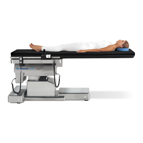
ALLEGRO™
MOBILE IMAGING TABLE
OWNER'S MANUAL
Model 6800
This manual is written in five
languages in the following order:
(en) English
•
(es) Spanish
•
(fr) French
•
(de) German
•
(it) Italian
•
MIZUHO OSI
NEWHIPNEWS.COM ·
•
UNION CITY, CA 94587
•
NEWSPINENEWS.COM
•
NW0510 Rev. D
Advertisement
Table of Contents

Related Manuals for Mizuho Allegro 6800


Summary of Contents for Mizuho Allegro 6800
- Page 1 (en) English • (es) Spanish • (fr) French • (de) German • (it) Italian • MIZUHO OSI 30031 AHERN AVENUE UNION CITY, CA 94587 • Bus: 510-429-1500 • Toll Free: 800-777-4674 Fax: • 510-429-8500 WWW.MIZUHOSI.COM · NEWHIPNEWS.COM · NEWSPINENEWS.COM • •...
- Page 2 IMPORTANT NOTICES CAUTION: To ensure safe operation of the equipment, please READ THESE INSTRUCTIONS COMPLETELY and keep this manual readily available for future reference. Carefully observe and comply with all warnings, cautions and instructions placed on the equipment or described in this manual. In this manual, the WARNING symbol is intended to alert the user to the presence of important operation, maintenance, or safety instructions.
-
Page 3: Table Of Contents
TABLE OF CONTENTS INTRODUCTION..........................5 1.1 General Description........................5 1.2 Specification ..........................5 1.2 Specification ..........................6 GLOSSARY OF TERMS........................7 2.1 Basic Assumptions Of Patient Orientation On The Tabletop ............7 COMPONENT IDENTIFICATION ....................... 9 3.1 Table Orientation........................... 9 3.2 Model Number And Serial Number .................... - Page 4 12.3 To Order Replacement Parts (RP).................... 56 12.4 Returns To Mizuho OSI (RGA) ....................56 12.5 To Send A Part For Repair (RA) ....................57 12.6 EC Authorized Representative....................57 13.0 Mizuho OSI ALLEGRO™ 6800 OPTIONAL ACCESSORIES ............58 MIZUHOSI 2009 NW0510 Rev. D...
-
Page 5: Introduction
Pressure is distributed evenly over the entire surface area. The pad is radiolucent, MR ® ® safe and latex free. The benefits of using MIZUHO OSI Tempur-Pedic are improved pressure management, reduced shear forces and enhanced patient comfort. -
Page 6: Specification
1.2 Specification • Maximum patient weight 450 lbs (205 kg) • Height range of table top 30 – 40 inches (76 - 102 cm) • Trendelenburg range 15° • Reverse trendelenburg 15° range • Powered lateral roll ±20° • Longitudinal travel 21 inches (53 cm) at speed of 2 to 4 inches (5 cm –... -
Page 7: Glossary Of Terms
2.0 GLOSSARY OF TERMS NOTE: The following terms are used throughout this owners manual. A thorough understanding of these terms is necessary to properly operate this table. 2.1 Basic Assumptions Of Patient Orientation On The Tabletop Our glossary of terms and technical procedures assume the patient is oriented with their head at the front of table and their feet at the rear of table as described below. - Page 8 floor. The floor locks, when down, prevent the table from moving on its wheels. The corresponding hand pendant buttons labeled FLOOR LOCK. Control panel, is a panel of buttons and lights located on the pedestal end of the table. Floor locks and tabletop home can be controlled by depressing the corresponding button labeled UP TO UNLOCK, DOWN TO LOCK or TABLE TOP HOME.
-
Page 9: Component Identification
3.0 COMPONENT IDENTIFICATION 3.1 Table Orientation The major components of the Allegro™ 6800 and control panel are shown in figure 2. The patient’s head can be located at either end of the table, depending on the procedure. Therefore, the table is described as having a pedestal end and a cantilever end. -
Page 10: Basic Operation
4.0 BASIC OPERATION 4.1 Control Operation For use with line power: Plug the power cord into a properly grounded receptacle. Refer to the label at the pedestal end of the base for input voltage requirements (see figure 4). Turn on the power switch and observe the green light in the switch indicating that power is applied to the table. -
Page 11: Hand Pendant
NOTE: The table will not function until the floor locks are completely deployed. Floor lock override button: If floor lock systems fails during table use, press and hold the FLOOR LOCK OVERRIDE button while simultaneously operating the desired hand pendant function. When button is released, no functions will be operable and this button must be pressed again if subsequent table movement is required. - Page 12 Height: To adjust the height of the table press and hold the appropriate HEIGHT UP or HEIGHT DOWN button until the desired height is achieved. Lateral roll: To adjust the lateral roll press and hold the appropriate LATERAL ROLL button. Note that when lateral roll is within +/- 2°...
- Page 13 FLOOR LOCK - STOWED FLOOR LOCK - ON HEIGHT DOWN HEIGHT UP TRENDELENBURG REVERSE TRENDELENBURG TRENDELENBURG - LEVEL LEFT LATERAL ROLL RIGHT LATERAL ROLL LATERAL ROLL LEVEL TOP FORWARD TOP AFT TOP RIGHT TOP LEFT TOP HOME RETURN TO LEVEL FLOOR LOCK FLOOR UNLOCK BATTERY STATUS...
-
Page 14: Joystick Control - Interactive Proportional Speed Control™ (Ipsc)
The controller considers the table to be level if it is within +/- 2° of 0° level. If the RETURN TO LEVEL button is pressed while the table is within this range, it will not move. If it is required to adjust the table to a position closer to 0°, simply press the appropriate function button on the hand pendant until the desired position is achieved. - Page 15 The joystick control includes an activation button (red button) that must be depressed to activate the joystick. This feature prevents unintended motion of the Allegro™ 6800 if the joystick is inadvertently pushed. To translate the Allegro™ 6800, press and hold down the JOYSTICK ACTIVATION button and then push the joystick in the intended direction of travel.
-
Page 16: Inspection
Carefully inspect all critical, inaccessible areas, joints, electrical cords and all movable parts for possible damage or non-function. Damaged or defective products should not be used or processed. Contact your local Mizuho OSI sales representative for repair or replacement. MIZUHOSI 2009 NW0510 Rev. D... -
Page 17: Function Check
Perform all steps in this procedure. If you have any questions please feel free to contact Mizuho OSI Customer Resource Group at 800-777-4674, 7AM to 5PM PST. For a complete definition of reference terms used in this procedure, please refer to the Glossary of Terms (Section 2) this owners manual. - Page 18 8. Floor lock override button check: 8.1. With floor locks not engaged, press and hold floor lock override button located under control panel. While holding the floor lock override button, operate the HEIGHT UP, HEIGHT DOWN, LEFT LATERAL ROLL, RIGHT LATERAL ROLL, TRENDELENBURG/REVERSE TRENDELENBURG.
- Page 19 10.13. Disorient tabletop by raising height approximately two inches, lateral roll tabletop and performing trendelenburg approximately five degrees. Press and hold RETURN TO LEVEL button. Tabletop first levels roll and trendelenburg and then after a three-second delay, the tabletop moves down. Observe that the table top is level and in its lowest height position when movement stops.
-
Page 20: The Electrical System
7.0 THE ELECTRICAL SYSTEM 7.1 Description The electrical system provides control of all the table functions and is comprised of a power cord, an on/off circuit breaker switch, wire harnesses, a power supply, a controller circuit, a hand pendant, a joystick control, floor lock jackscrews, various electromechanical actuators, two stepper motors and two batteries. -
Page 21: Battery Charging
indicator light on the control panel or the hand pendant. This button applies electrical current to each of the four jackscrew motors. Each leg is monitored by the controller for contact with the floor. In the case of an uneven floor, it is possible that one or more legs will continue to extend until firm contact is made with the floor. -
Page 22: Battery System
• Battery ordering number: NV0801; failure to use an approved Mizuho OSI battery, voids warranty and can cause harm to equipment. 1. Turn power switch off, wait 30 seconds for discharge, unplug power cord from wall outlet. - Page 23 NOTE: If this does not happen, immediately turn power switch off; verify proper battery connections, verify hand pendant is fully connected to table receptacle. Repeat test again. If problem continues, contact Mizuho OSI Customer Resource Group at 800-777- 4674 for further assistance.
-
Page 24: Cleaning
Tempur-med ® ® IMPORTANT: The MIZUHO OSI Tempur-Pedic pad should always be stored in a flat position. It can actually get stiff in cold temperatures and can crack and break if in a rolled position. It is important that you allow the pad to warm to room temperature before attempting to utilize or handle it. -
Page 25: Lubrication
• Do not lift, slide or carry MIZUHO OSI® Tempur-med® pads by grabbing the fabric. The cover may tear or rip. • The pad is intended to be cleaned in place. It does not need to be rotated or flipped. -
Page 26: Troubleshooting
This override button only powers the height, trendelenburg and lateral roll functions on the hand pendant and is intended for emergency situations only. If it becomes necessary to use this feature, call Mizuho OSI Customer Resource Group immediately to arrange for table service. - Page 27 CAUTION: Electrical shock hazard exists with access covers removed; use caution when working in exposed areas. 1. Measure voltage at wall outlet to verify proper AC input is available (120V or 230V). 2. Inspect power supply cord for physical damage, continuity, and adequate resistance. 3.
- Page 28 • Verify power cord is plugged into a properly grounded AC receptacle. • If on battery power, verify proper charge; observe battery status LED illuminates green. • Verify table power switch is on. • Activate floor lock override; press and hold FLOOR LOCK OVERRIDE button (located under control panel).
- Page 29 • Call Mizuho OSI Customer Resource Group for service or parts (possible hand pendant and/or 10 Amp motor-control PCB). Trendelenburg or reverse trendelenburg not functioning: • Press and the hold hand pendant TREN or REV.TREN button. Observe tabletop movement. • Verify the hand pendant is properly plugged into a hand pendant receptacle.
- Page 30 • Call Mizuho OSI Customer Resource Group for service or parts (possible hand pendant and/or 10 Amp motor-control PCB). Top forward or top aft not functioning: • Press and hold hand pendant TOP FORWARD or TOP AFT control button. Observe tabletop movement.
- Page 31 Top home not functioning on the hand pendant: • Press and hold hand pendant TOP HOME button. Observe tabletop movement. • Call Mizuho OSI Customer Resource Group for service or parts (possible hand pendant and/or 10 Amp motor-control PCB). Table top home not functioning on the control panel: •...
- Page 32 Joystick variable speed operation not functioning: • Call Mizuho OSI Customer Resource Group for service or parts. Joystick speed select button not functioning: • Call Mizuho OSI Customer Resource Group for service or parts. Joystick: 1. Perform all indicated functions per functional check.
-
Page 33: Removal And Replacement Of Components
10.0 REMOVAL AND REPLACEMENT OF COMPONENTS 10.1 Floor Lock Foot Actuator Coupling and set-screw Crank handle Floor lock Floor lock (raised) (lowered) Support block Figure 11: Foot end base: Cover removed, raised with support block and crank handle Replacement procedure: 1. -
Page 34: Floor Lock Pad
10. Loosen floor lock actuator coupling setscrew using 1/8-inch hex key. Slide coupling towards actuator. 11. Remove actuator by removing the two socket-head cap screws using 3/16-inch hex key. 12. Replace floor lock actuator assembly (see Replacement/Spare Parts List section) or pad as described below. -
Page 35: Power Supply Tray
10.3 Power Supply Tray The power supply tray contains the system power supply PCB, transformer, DC batteries, power switch/circuit breaker, component circuit breakers and power cord receptacle. Battery-A Battery-B Figure 13: Power supply tray, base cover removed Figure 14: Base cover and power supply tray removal MIZUHOSI 2009 NW0510 Rev. -
Page 36: Controller Circuit
Replacement procedure: 1. Turn power switch off. Wait 30 seconds for discharge, then unplug power cord from wall outlet. 2. Remove pedestal end base cover by removing the six screws using 1/8 in hex key. CAUTION: Electrical shock hazard exists with access covers removed; use caution when working in exposed areas. -
Page 37: 10-Amp Motor Control Pcb
10.5 10-Amp Motor Control PCB Replacement procedure: 1. Turn the power switch off. Wait 30 seconds for discharge, then unplug power cord from wall outlet. 2. Remove pedestal end base cover by removing the six screws using 1/8 in hex key. CAUTION: Electrical shock hazard exists with access covers removed;... -
Page 38: Stepper Controller Tray
10.6 Stepper Controller Tray Stepper control interface PCB Y-Axis stepper PCB X-Axis stepper PCB Figure 16: Stepper control tray assembly Replacement procedure: 1. Turn the power switch off. Wait 30 seconds for discharge, then unplug power cord from wall outlet. 2. - Page 39 f. P6 - Senders g. P7 - Analog I/O h. P8 - Digital I/O 6. Remove cables from stepper driver PCBs. NOTE: Y stepper PCB is above and cables marked white, X stepper below marked black. a. J2 - Power b.
-
Page 40: Tilt Sensor Actuator
Table floor lock system test procedure: Using hand pendant and control panel, operate floor lock and unlock buttons through their full range and verify that 1. All four floor lock motors move while the button is pressed and all motors stop when the button is released. -
Page 41: Left Tilt Cover Removal (The Bell Shaped Housing)
1. Turn power switch on. The green light illuminates. 2. Press and hold DOWN TO LOCK button until green LOCKED WHEN LIT light illuminates. 3. Move tabletop to highest position and maximum left lateral roll using hand pendant. 4. Move tabletop to maximum left translation position using joystick. 5. - Page 42 4. Replace in reverse order. Attach harness to sensor bracket, as needed, with small nylon cable tie. Use care to prevent possible damage by moving parts. Tilt sensor calibration: NOTE: Use a bubble level resting on the tabletop as a level gauge. The level sensor adjustment screws are accessed from the top of the unit.
- Page 43 b. Move the tabletop with the joystick to maximum left position for best screw clearance and easiest access. c. Install the seven screws attaching the left and right tilt covers using a 1/16 inch hex key. 17. Attach X-Y stage cover. a.
-
Page 44: Technical Drawings And Parts Lists
11.0 TECHNICAL DRAWINGS AND PARTS LISTS 11.1 Electrical Interconnect Diagram, 120 VAC MIZUHOSI 2009 NW0510 Rev. D... -
Page 45: Electrical Interconnect Diagram, 230 Vac
11.2 Electrical Interconnect Diagram, 230 VAC MIZUHOSI 2009 NW0510 Rev. D... -
Page 46: Top Level Table Assembly Exploded View
11.3 Top Level Table Assembly Exploded View 24 3X 10 7X 23 2X 17 2X (REF) 6800-290 HAND PENDANT SWIVEL MOUNT, ASSY NP1816 WARNING LABEL, NOT FOR STORAGE NG0752 #10-32 PEM SELF CLINCHING SS NB0331 RUBBER BUMPER #10 FEMALE THREAD AAAW075BAC 1/4-20 X .75 SST FLHD SKT SCR AAAT075BAC... - Page 47 11.4 Table Sub Assembly Parts List AAAW050CA 1/4-20 X .50 HEX HD CAP SCR MZNP1811 LABEL, EQUIPOTENTIAL AAAW050BAC 1/4-20 X .50 SST FLHD SKT SCR AM062200 .625 DIA X 2.00 SST DOWEL PIN AAAT125CAC #10-32 X 1.25 SST CAP HD SKT SCR ADAHEC #4 NYLOCK NUT, SST AAAT125BAC...
- Page 48 11.5 Table Assembly Exploded View NOTE: Numbers correspond to item numbers on parts list in section 11.4. X-Y Coupler assembly Y-Ring assembly X-Ring assembly 106 4X 20 2X Power supply 43 (REF) 123 4X Batteries 10 Amp controller Stepper- 115 (REF) controller 88 (REF) (REF)
-
Page 49: Base Cover Assembly Exploded View
11.6 Base Cover Assembly Exploded View NOTE: Numbers correspond to item numbers on parts list in section 11.4. Base Assembly Exploded View 63 6X 54 5X 10⁷ 3" X 4.5" 64 6X 3" X 4.5" 55 2X 63 2X 10² 4X 59 2X 10⁷ 3"... -
Page 50: Base Assembly Exploded View
11.7 Base Assembly Exploded View NOTE: Numbers correspond to item numbers on parts list in section 11.4. 63 6X 54 5X 10⁷ 3" X 4.5" 3" X 4.5" 55 2X 63 2X 59 2X 10⁷ 3" X 13" 66 2X 127 3X MIZUHOSI 2009 NW0510 Rev. -
Page 51: X-Ring Assembly Exploded View
11.8 X-Ring Assembly Exploded View NOTE: Numbers correspond to item numbers on parts list in section 11.4. MIZUHOSI 2009 NW0510 Rev. D... -
Page 52: Y-Ring Assembly Exploded View
11.9 Y-Ring Assembly Exploded View NOTE: Numbers correspond to item numbers on parts list in section 11.4. 64 3X 57 2X 56 3X 77 2X 63 2X 75 2X 62 2X 80 3X 11.10 Y-Ring Assembly Bottom View NOTE: Numbers correspond to item numbers on parts list in section 11.4. 91 16X MIZUHOSI 2009 NW0510 Rev. -
Page 53: Y Coupler Assembly Exploded View
11.11 X - Y Coupler Assembly Exploded View NOTE: Numbers correspond to item numbers on parts list in section 11.4. 105 2X 82 2X 64 3X 10³ 4X MIZUHOSI 2009 NW0510 Rev. D... -
Page 54: Y Coupler Assembly Bottom View
11.12 X - Y Coupler Assembly Bottom View NOTE: Numbers correspond to item numbers on parts list in section 11.4. 95 2X 95 4X 65 6X 31 2X 71 6X 10⁸ 4X MIZUHOSI 2009 NW0510 Rev. D... -
Page 55: Replacement/Spare Parts List
11.13 Replacement/Spare Parts List 10-Amp motor controller PCB 6800-1021 Base cover, floating 6800-129 Base cover, mid section 6800-130 Battery, 12V, 12A (2x reqd) NV0801 Column skirt, fixed, left 6800-267 Column skirt, fixed, right 6800-268 Column slider cover 6800-127 Floor lock gearbox assembly 6800-210 Floor lock motor 6800-217... -
Page 56: Mizuho Osi Customer Resource Group
12.0 Mizuho OSI CUSTOMER RESOURCE GROUP 12.1 Contact For Parts And Service For detailed repair information or to order replacement parts, call the Mizuho OSI Customer Resource Group: 1-800-777-4674 A Customer Resource Group line is available from 7AM-5PM PST, Monday through Friday. -
Page 57: To Send A Part For Repair (Ra)
12.5 To Send A Part For Repair (RA) 1. If unable to identify part, please call, fax or e-mail to Customer Resource Group. 2. If part is known please telephone, fax or e-mail part number and description to Customer Resource Group for Repair Authorization (RA) number. 3. -
Page 58: Mizuho Osi Allegro™ 6800 Optional Accessories
13.0 Mizuho OSI ALLEGRO™ 6800 OPTIONAL ACCESSORIES Figure 18: Stent tray Stent tray (Part# 6900-21) The stent tray is designed for and intended to support guide wires, stents and catheters. It can be mounted on either the pedestal or cantilever end of the table. - Page 59 Figure 21: Radiolucent AV fistula board Radiolucent AV fistula board (Part# 6900-25) A radiolucent platform for performing upper extremity procedures. The radiolucent AV fistula board has a 2 inch (5 cm) pad and attached auxiliary clamp for securing to the table top.
- Page 60 Figure 24: Hand pendant Hand pendant (Part# 6807-3) See section 4.0 Basic Operation, for a complete description Figure 25: Swivel mount for hand pendant Swivel mount for the hand pendant (Part# 6800-290) The swivel mount allows for mounting the hand pendant horizontally on the side rail or auxiliary clamp.
- Page 61 Figure 27: Universal foot board with two side rail adaptors Universal foot board (includes two side rail adaptors) (Part# 6900-51) The universal foot board mounts on the side rail or auxiliary clamps and is designed to provide support in maintaining the patient’s desired position in the table when the table is placed in reverse trendelenburg.
Need help?
Do you have a question about the Allegro 6800 and is the answer not in the manual?
Questions and answers