Table of Contents
Advertisement
Quick Links
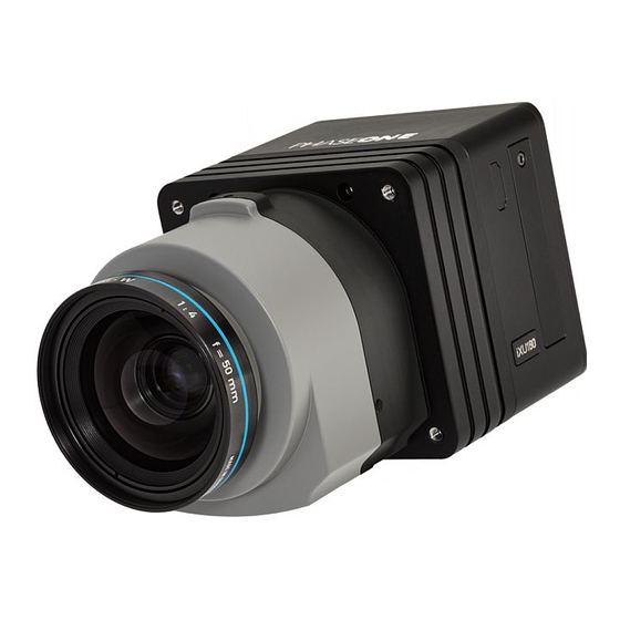
Phase One
iXU-RS/iXU-R/iXU
Aerial Camera System
Installation Guide
This guide is designed to assist you
with the installation of your new Phase One
iXU-RS or Phase One iXU-R or Phase One iXU
camera system.
As new features are introduced through
firmware updates, we change the
downloadable version of this document,
which is available from the
Downloads section of
http://industrial.phaseone.com.
1
Advertisement
Table of Contents

Related Manuals for PhaseOne iXU-RS


Summary of Contents for PhaseOne iXU-RS
- Page 1 Aerial Camera System Installation Guide This guide is designed to assist you with the installation of your new Phase One iXU-RS or Phase One iXU-R or Phase One iXU camera system. As new features are introduced through firmware updates, we change the...
-
Page 2: Table Of Contents
Mounting a Lens on an iXU-RS/iXU-R ........30 Configuring Camera for Image Storage ........60 5. Connecting a Camera ................32 8. Video Display — iXU 1000/iXU-RS 1000 and iXU 150 ..62 Attaching the Camera to a Pod ............32 Activating HDMI Video Output ............62 Connecting a Control Cable ............. -
Page 3: What's In The Box
Adjusting ISO ................... 68 1. What’s in the Box? Adjusting Exposure Time ..............69 Using Video Mode Without a Monitor — iXU 1000 iXU-RS 1000 and iXU 150 ................... 70 • Phase One iXU-RS or iXU • 4 mm flat screwdriver... -
Page 4: Overview
15. FMC button or Video iXU Camera System button - iXU 150, iXU 1000 11. USB 3.0 port screw 1. Pod mounting threaded holes (4) and iXU-RS 1000 (including 12. Data terminal A NIR variations) 2. Lens secure cams (3) 16. Setup button 3. -
Page 5: Ixu-Rs Camera System
12. Data terminal B 8. Menu button 13. Power terminal 1. Pod mounting threaded holes (4) 9. USB 3.0 port cover 14. For iXU-RS - FMC or 2. Lens screws (3) Video button 10. USB 3.0 port screw 3. Lens assembly For iXU-R - FMC button 11. -
Page 6: Preflight Planning
3. Preflight Planning Exposure Sequence To learn more about the capabilities of the iXU-RS/iXU-R/iXU camera, consult the industrial.phaseone.com website and the Trigger In documents, which are found on the USB drive that comes with the camera. System Ready Understanding the Exposure Sequence... -
Page 7: Wiring A Control Cable
Common Common VIL — maximum voltage level that is interpreted as a ‘0’ by a input. *For iXU-RS/iXU-R/iXU cameras, this connection is mandatory. VIH — minimum voltage level that is interpreted as a ‘1’ by a input. The connection is not necessary for iXA-R/iXA cameras. -
Page 8: Wiring A Control Cable For An Ixu Series Camera
Wiring a Control Cable for an iXU Series Software Activation of Black Reference Camera The Phase One iXU-RS/iXU-R/iXU camera can perform a black reference sequence by using the iX Capture External devices are connected to the camera with an iXU application, the Phase One SDK, the Flight Management RA control cable (supplied with the camera kit). -
Page 9: Wiring The Power Cable
2 Black DC In - (Common) Input Figure 4: Figure 5: Power Cable Plug Pinout iXU-RS/iXU-RS/iXU-R/iXU Camera Socket Pinout Note: The iXU-RS/iXU-R/iXU camera must only be powered by a limited fused power source, up to 8 A single fault condition. -
Page 10: Electrical Interfaces
Electrical Interfaces Mid-exposure pulse There are four signals that are used to communicate with and control an iXU-RS/iXU-R/iXU camera: Trigger in Triggers the iXU-RS/iXU-R/iXU for new capture cycle Black Indicates a black reference sequence is reference required Mid- A signal indicates the midpoint of the exposure exposure time. -
Page 11: Preparing The Camera
4. Preparing the Camera Rotate the front body cap counterclockwise and lift out. Mounting an iXU Lens Note: Before mounting or dismounting a lens, ensure that the power cable is not attached to the camera. Ensure that the three lens clamp cams are in the unlocked position. -
Page 12: Dismounting An Ixu Lens
Dismounting an iXU Lens With a flat screwdriver, unlock each of the three lens clamp cams by rotating each plunger 90 degrees counter clockwise. Rotate lens clockwise until it locks into place. Locked Unlocked Push and hold the lens release button toward the camera. With a flat screwdriver, lock each of the three lens clamp cams by rotating each cam clockwise 90 degrees. -
Page 13: Attaching A Focus Lock Band
Rotate the lens counterclockwise and lift out. Attaching a Focus Lock Band The focus lock band is used to keep your lens set to the focus you prefer. Follow the instructions below to secure your lens to the exact focus you choose. To attach a Focus Lock Band to your lens: Check to make sure that both front band and rear band screws are loosened. - Page 14 Slide the Focus Lock Band onto the lens as far as it can go. Perform ground calibration until optimal focus has been The rear band should be positioned closest to the achieved. camera body and the alignment hole in the rear band is Using a 2 mm hex key, tighten the screw on the front positioned over the white alignment dot on the lens.
-
Page 15: Dismounting A Lens From An Ixu-Rs/Ixu-R
Dismounting a Lens from an iXU-RS/iXU-R Pull the lens assembly away from the camera. Lenses on the iXU-RS/iXU-R series of cameras are easily dismounted. Ensure that you only dismount lenses in a clean environment. Place a soft cloth down on the table to avoid scratching the LCD and a lens cap on the lens. -
Page 16: Mounting A Lens On An Ixu-Rs/Ixu-R
With a 2 mm hex key, secure the lens assembly onto the iXU-RS/iXU-R by gently tightening each locking screw. Lenses on the iXU-RS/iXU-R series of cameras are easily Tighten the locking screws a second time using a torque mounted. Ensure that you only mount lenses in a clean of 50 cNm. -
Page 17: Connecting A Camera
Attaching the Camera to a Pod Insert the iXU RA power cable to the power input of the iXU- RS/iXU-R/iXU camera. Attach the iXU-RS/iXU-R/iXU camera to a pod using four M4 Connect the other end of the iXU RA power cable to the bolts. -
Page 18: Connecting Control Cables To Devices
Connect the other end of the iXU RA control cable into Connecting Control Cables to Devices the GPS/IMU. Depending on how you choose to configure your iXU-RS/ iXU-R/iXU, the camera can be connected to the following: • Flight Management System •... -
Page 19: Connecting Cables For Multiple Camera Configuration
GPS/IMU Management Configuration System Multiple iXU-RS/iXU-R/iXU cameras can be synchronized to shoot simultaneously. When using iXU-RS/iXU-R/iXU cameras, ensure that you have mounted Schneider-Kreuznach fast sync [S] lenses on the cameras. The first camera in the daisy-chain is triggered with an iXU RA control cable. -
Page 20: Activating Fast Sync Mode
Activating Fast Sync Mode Use Fast Sync Mode when you are using two or more synchronized cameras in the same array. Ensure that Fast Sync Mode is set according to your preference. To deactivate Fast Sync Mode, follow the "Deactivating Fast Sync Mode" on page 39. -
Page 21: Connecting Ixu-Rs/Ixu-R/Ixu And Ixa-R/Ixa Cameras In The Same Array
Connect the other end of the iXU RA control cable into the Aircraft GPS/IMU. power bus If the next camera in the array is an iXU-RS/iXU-R/iXU: Control cable* Insert a multi-sync cable into the iXU-RS/iXU-R/iXU's Multi-sync cable data terminal B (right one). -
Page 22: Checking Compatibility Of Usb 3.0 Cards
Checking Compatibility of USB 3.0 Cards For a list of USB 3.0 cards for Windows computers that have been tested with the iXU-RS/iXU-R/iXU camera, read the USB 3.0 Compatibility document available in the Downloads section of the http://industrial.phaseone.com website. Connecting a USB 3.0 Cable to an Onboard Computer To connect a USB 3.0 cable to a computer:... -
Page 23: Connecting A Gps/Imu
GPS receiver, the parameters in your GPS RS232. receiver and camera must match. To use iX Link with your iXU-RS/iXU-R/iXU camera, you need Note: The GPS receiver must use the same baud rate as the camera (9600, 19200, 57600 or 115200). -
Page 24: Activating Ix Link
Activating Forward Motion Compensation Forward Motion Compensation (FMC) is an option on the iXU-RS 180, iXU-RS 160 and iXU-RS 160 Achromatic, iXU-R 180, iXU-R 160 and iXU-R 160 Achromatic. iXU 180, iXU 160 and iXU 160 Achromatic. To order FMC, view http://industrial.phaseone.com/PhaseOne-FMC.aspx. -
Page 25: Using A Near Infrared Camera
Using a Near Infrared Camera Select the lens filter that you are using: • IR Cut — For RGB photography If the camera model is a Near Infrared (NIR) model, follow the • IR 830nm — For NIR photography above 830 nm steps below to configure the camera for NIR or RGB use. -
Page 26: Using Auto Exposure
6. Using Auto Exposure The camera uses the following parameters for the first exposure: • ISO — Value selected in Auto Exposure Minimum. • Aperture — Average aperture between Auto Exposure The camera’s exposure parameters can be controlled Minimum and Maximum. manually or with auto exposure by adjusting the settings on the camera’s LCD screen or with iX Capture. -
Page 27: Selecting Auto Exposure Range
Selecting Auto Exposure Range The default auto exposure range settings are: iXU-RS iXU-RS 180 iXU-RS 160 To keep your exposure parameters within the range you 1000 iXU-R 180 Achromatic prefer, set Auto Exposure Minimums and Maximums. iXU-R 1000 iXU 180... -
Page 28: Selecting Auto Exposure Priority
Selecting Auto Exposure Priority Click AE Priority. The AE Priority screen appears. Auto Exposure Priority is the method in which the camera adjusts the three exposure parameters (ISO, aperture and shutter speed) to ensure proper exposure. When in Auto Exposure Mode, if an exposure adjustment is needed, the camera adjusts the first parameter until it reaches the minimum or maximum that you choose, then goes to the second parameter and if needed, continues to the third. -
Page 29: Adjusting Auto Exposure Bias
Activating Auto Exposure Mode Adjusting Auto Exposure Bias To activate Auto Exposure Mode: Auto exposure settings can be adjusted to add or remove From the Home screen, tap Setup > Exposure Mode. exposure bias (compensation). Some users prefer to use the The Exposure Mode screen appears. -
Page 30: Storing Images
The CompactFlash card is inserted in the slot located under Note: To eject the card push the small button above the card the cover on the left hand side of the iXU-RS/iXU-R/iXU once, and an ejecting pin comes out. Pushing this pin all the camera. -
Page 31: Configuring Camera For Image Storage
Configuring Camera for Image Storage The camera enables storage of images either via a USB 3.0 connection or on an internal CompactFlash card. Configure the camera to suit your chosen storage method. Image Storage Options Auto The camera stores images to a computer connected via USB 3.0 or CompactFlash card. -
Page 32: Video Display - Ixu 1000/Ixu-Rs 1000 And Ixu 150
The HDMI Video Output screen appears. iXU 1000/iXU-RS 1000 and iXU 150 The iXU 1000/iXU-RS 1000 is built with HDMI output capability, offering a choice of viewing the video feed on the camera's LCD or outputting to an external display. Follow the instructions below for working with the different video modes. -
Page 33: Configuring Hdmi Control
Configuring HDMI Control Configuring HDMI Mode Before configuring HDMI control, HDMI video output must be To configure the HDMI output: activated. See "Activating HDMI Video Output" on page 62. Go to Home screen > HDMI > HDMI Mode. The HDMI controls can be reached by clicking HDMI on the Home screen or in the contextual menu. -
Page 34: Selecting Hdmi Crop
Selecting HDMI Crop From the Exposure Mode screen, select either: • Auto To select the HDMI crop: • Manual Go to Home > HDMI >Crop The HDMI Control screen appears with your selection The Crop screen appears. displayed. Note: If Auto is selected, follow the instructions in "Adjusting Lightness"... -
Page 35: Adjusting Iso
Adjusting ISO Adjusting Exposure Time When using Manual Mode, the sensitivity can be raised or When using Manual Mode for video, the exposure time can lowered to produce different results on your monitor. be adjusted to produce different results on your monitor. To adjust the ISO: Go to Home screen >... -
Page 36: Using Video Mode Without A Monitor - Ixu 1000 Ixu-Rs
Using Video Mode Without a Monitor — iXU 1000 Tap the LV soft button on the Home screen or the LV icon found in the contextual menu. iXU-RS 1000 and iXU 150 The camera enters video mode. An image is displayed on the camera's touchscreen. -
Page 37: Firmware
Application To install the Phase One Firmware Updater Application, download it from the Downloads section of the industrial. phaseone.com website and do the following: Open the zip file, extract and store the FWUpdater.msi. Double-click FWUpdater.msi to start the Firmware Updater Setup Wizard. -
Page 38: Updating The Firmware
• Your computer has the Firmware Updater application installed and the computer is connected to the Internet. To update the iXU-RS/iXU-R/iXU firmware: Connect the camera to the computer with a USB 3.0 cable. If displayed, click the link to download the firmware. -
Page 39: Restoring The Firmware
Restoring the Firmware After downloading the new firmware, the Release Notes button is no longer grayed out. In the event you need to restore the sensor module’s firmware to the factory version. (Camera settings are not affected): Go to Menu > Firmware. The Firmware screen appears. - Page 40 Visit the website for additional information industrial.phaseone.com © Phase One 2014-2020 85036000 - iXU-RS/iXU-R/iXU Installation Guide 2.91...
Need help?
Do you have a question about the iXU-RS and is the answer not in the manual?
Questions and answers