
Related Manuals for Shimano FC-T8000


Summary of Contents for Shimano FC-T8000
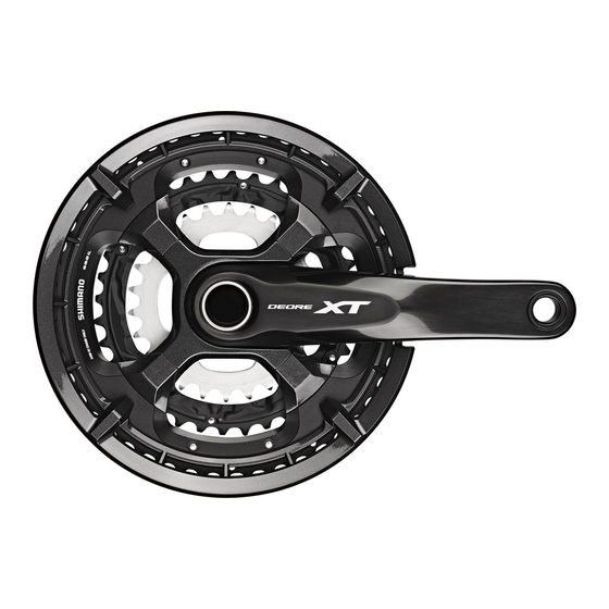
- Page 1 (English) DM-TRFC001-04 Dealer's Manual ROAD Trekking City Touring/ URBAN SPORT E-BIKE Comfort Bike Crankset DEORE XT FC-T8000 DEORE FC-T6010 Bottom bracket BB-MT800 BB-MT801 BB-MT800-PA DEORE SM-BB52 BB-MT501 BB-MT500-PA...
-
Page 2: Table Of Contents
CONTENTS IMPORTANT NOTICE ....................3 TO ENSURE SAFETY ....................4 LIST OF TOOLS TO BE USED .................. 8 INSTALLATION ..................... 10 Threaded bottom bracket ........................10 PRESS-FIT BB ...............................13 Installing the crank arms ...........................16 MAINTENANCE ....................19 Replacing chainrings ..........................19... -
Page 3: Important Notice
• All manuals and technical documents are accessible online at https://si.shimano.com. • For consumers who do not have easy access to the internet, please contact a SHIMANO distributor or any of the SHIMANO offices to obtain a hardcopy of the User's Manual. -
Page 4: To Ensure Safety
• Be sure to follow the instructions provided in the manuals when installing the product. Only use SHIMANO genuine parts. If a component or replacement part is incorrectly assembled or adjusted, it can lead to component failure and cause the rider to lose control and crash. - Page 5 • This product is not warrantied against damage caused by improper use, abuse, or issues resulting from a crash, unless the circumstance was caused by a manufacturing fault. • Products are not guaranteed against natural wear and deterioration from normal use and aging. • For maximum performance we highly recommend SHIMANO lubricants and maintenance products.
- Page 6 TO ENSURE SAFETY For Installation to the Bicycle, and Maintenance: • When installing the pedals, apply a small amount of grease to the threads to prevent the pedals from seizing. Use a torque wrench to securely tighten the pedals. Tightening torque is 35 - 55 N·m. The right crank arm has a right-hand thread, and the left crank arm has a left-hand thread. •...
-
Page 7: List Of Tools To Be Used
LIST OF TOOLS TO BE USED... - Page 8 LIST OF TOOLS TO BE USED LIST OF TOOLS TO BE USED The following tools are needed for installation, adjustment, and maintenance purposes. Tool Tool Tool 5 mm hexagon wrench TL-FC16 TL-FC36 8 mm hexagon wrench TL-FC18 TL-FC37 17 mm spanner TL-FC25 TL-BB12 Screwdriver [#2]...
-
Page 9: Installation
INSTALLATION... -
Page 10: Threaded Bottom Bracket
INSTALLATION Threaded bottom bracket INSTALLATION „ Threaded bottom bracket List of tool combinations Use the tools in the correct combination. BB-MT800 / BB-MT801 NOTICE TL-FC25 & TL-FC32 TL-FC25 & TL-FC33 • For an impact wrench, use TL-FC37. Using TL-FC25 other tools may damage the tool. •... - Page 11 INSTALLATION Threaded bottom bracket Spacer installation method Check whether the width of the bottom bracket shell is 68 mm or 73 mm. Bottom bracket shell width Install the cups. 68 mm 73 mm 2.5 mm spacer 1.8 mm spacer 0.7 mm spacer Chain case stay Band type Chain case...
- Page 12 Threaded bottom bracket Installation to the bottom bracket shell Grease the left- and right-hand cups and Inner cover use the SHIMANO original tool to install Right-hand cup (left-hand thread) the right-hand cup of the bottom Left-hand cup bracket, the inner cover and the (right-hand thread) left-hand cup of the bottom bracket.
-
Page 13: Press-Fit Bb
INSTALLATION PRESS-FIT BB „ PRESS-FIT BB BB-MT800-PA / BB-MT500-PA Bottom bracket cups Left-hand cup Inner cover Right-hand cup Bottom bracket shell width 2.5 mm spacer NOTICE Some models do not need spacers. Assembly example Bottom bracket shell with 92 mm width Bottom bracket shell with 89.5 mm width 2.5 mm spacer NOTICE... - Page 14 INSTALLATION PRESS-FIT BB Installation to the bottom bracket shell Insert the bottom bracket into the bottom bracket shell. Insert the SHIMANO original tool into TL-BB12 the bottom bracket. Press fit the bottom bracket by 8 mm hexagon wrench tightening with a spanner while making...
- Page 15 While holding down the end of the removal tool, push the tool in from the other side until it locks in place. Tap the SHIMANO original tool with a Soft face mallet soft face mallet until the end of the bottom bracket is ejected.
-
Page 16: Installing The Crank Arms
Wide groove area (axle) crank arm unit where the groove is wide. Apply grease: Premium Grease (Y04110000) Use the SHIMANO original tool to TL-FC16 tighten the cap. Apply grease: Premium Grease (Y04110000) Tightening torque 0.7 - 1.5 N·m... - Page 17 INSTALLATION Installing the crank arms Push in the stopper plate and check that Plate pin the plate pin is securely in place, and Stopper plate then tighten the screws of the left crank Left crank arm arm. Tighten both screws equally to the Tightening torque specified tightening torque (12 - 14 N·m).
-
Page 18: Maintenance
MAINTENANCE... -
Page 19: Replacing Chainrings
MAINTENANCE Replacing chainrings MAINTENANCE „ Replacing chainrings Installation of the chain guard Attach the chain guard to the largest chainring as shown in the illustration. Marking Flat areas The marked side of the largest chainring should face outward. Position the chain guard so that the flat areas align with the holes in the largest chainring. Tightening torque 1.5 - 2 N·m... - Page 20 MAINTENANCE Replacing chainrings Installing the chainrings (FC-T8000) With the marked side of the largest chainring facing outward, set the chainring so that the Marking hole is positioned under the crank arm. Hole Crank arm To be continued on next page...
- Page 21 MAINTENANCE Replacing chainrings Set the middle chainring so that the marked side faces inward and the alignment tab is Crank arm positioned under the crank arm. Alignment tab Decorative nuts Install the largest chainring and middle chainring using decorative nuts as shown in the Mounting bolts illustration.
- Page 22 MAINTENANCE Replacing chainrings With the marked side of the smallest chainring facing inward, set the smallest chainring so Crank arm that the alignment tab is positioned under the crank arm. Alignment tab Mounting bolts Marking Smallest chainring Tightening torque 16 - 17 N·m...
- Page 23 MAINTENANCE Replacing chainrings Installing the chainrings (FC-T6010) With the marked side of the largest chainring facing outward, set the chainring so that the Marking hole is positioned under the crank arm. Hole Crank arm Set the middle chainring and the smallest chainring so that the marked sides face inward Crank arm and the alignment tab on each chainring is positioned under the crank arm.
- Page 24 Please note: specifications are subject to change for improvement without notice. (English) © May 2022 by SHIMANO INC. ITP...
Need help?
Do you have a question about the FC-T8000 and is the answer not in the manual?
Questions and answers