Sign In
Upload
Download
Table of Contents
Contents
Add to my manuals
Delete from my manuals
Share
URL of this page:
HTML Link:
Bookmark this page
Add
Manual will be automatically added to "My Manuals"
Print this page
×
Bookmark added
×
Added to my manuals
Manuals
Brands
Shimano Manuals
Bicycle Accessories
SLX BR-M7000
Dealer's manual
Shimano SLX BR-M7000 Dealer's Manual
Hydraulic disc brake
Hide thumbs
1
Table Of Contents
2
3
4
5
6
7
8
9
10
11
12
13
14
15
16
17
18
19
20
21
22
23
24
25
26
27
28
29
30
31
32
33
34
35
36
37
38
39
page
of
39
Go
/
39
Contents
Table of Contents
Bookmarks
Advertisement
Table of Contents
1
Table of Contents
1
Important Notice
2
To Ensure Safety
3
List of Tools to be Used
4
Installation
4.1
Disc Brake Mount Adapter (for 180Mm Disc Brake Rotors)
4.2
Disc Brake Rotor Adapter
4.3
Brake Hose
5
Maintenance
5.1
Adding Shimano Genuine Mineral Oil and Bleeding Air
5.2
Replacing the Brake Hose
5.3
Replacing the Brake Pads
Download this manual
(English)
ROAD
City Touring/
Comfort Bike
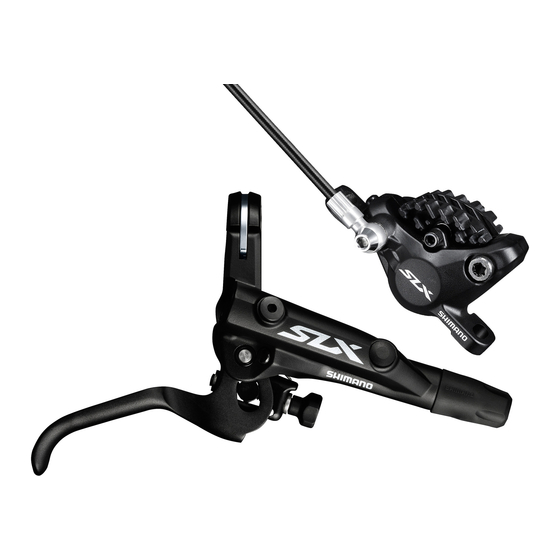
Hydraulic Disc Brake
SLX
BR-M7000
BL-M7000
DEORE
BR-M6000
BL-M6000
Non-Series
BR-MT500
BL-MT500
Mount adapter
SM-MA-F180P/P2
MTB
URBAN SPORT
DM-MBBR001-02
Dealer's Manual
Trekking
E-BIKE
Table of
Contents
Previous
Page
Next
Page
1
2
3
4
5
Advertisement
Table of Contents
Need help?
Do you have a question about the SLX BR-M7000 and is the answer not in the manual?
Ask a question
Questions and answers
Related Manuals for Shimano SLX BR-M7000
Bicycle Accessories Shimano BR-M8000 Dealer's Manual
Hydraulic disc brake (39 pages)
Adapter Shimano SM-MA-F180P/P2 Dealer's Manual
(24 pages)
Bicycle Accessories Shimano BR-R550 Service Instructions Manual
Multi-condition brake system / cantilever brake (2 pages)
Bicycle Accessories Shimano ALFINE DISC BRAKE SYSTEM - TECHNICAL Service Instructions
Disc brake system (1 page)
Bicycle Accessories Shimano DISC BRAKE SYSTEM - TECHNICAL SERVICE INSTRUCTIONS FOR CROSS-COUNTRY Service Instructions
Disc brake system (for cross-country) (1 page)
Shimano ST-M410, BR-M545, SM-RT61, SM-RT62 - Disc Brake System Manual
(article)
Bicycle Accessories Shimano BR-C6000 Dealer's Manual
Hub roller brake (27 pages)
Bicycle Accessories Shimano BR-M6100 Dealer's Manual
Hydraulic disc brake (59 pages)
Bicycle Accessories Shimano BR-M6120 Dealer's Manual
Hydraulic disc brake (59 pages)
Bicycle Accessories Shimano BR-MT410 Dealer's Manual
Hydraulic disc brake (59 pages)
Bicycle Accessories Shimano Non-Series BR-MT500 Dealer's Manual
Hydraulic disc brake (39 pages)
Bicycle Accessories Shimano BR-M965 Service Manual
Disc brake systems (41 pages)
Bicycle Accessories Shimano TIAGRA BR-4400 Service Instructions
Caliper brake (3 pages)
Bicycle Accessories Shimano BR-3300 Manual
(3 pages)
Bicycle Accessories Shimano BR-M9100 Dealer's Manual
Hydraulic disc brake (67 pages)
Bicycle Accessories Shimano GRX RX 815 Series Dealer's Manual
(192 pages)
This manual is also suitable for:
Slx bl-m7000
Deore br-m6000
Deore bl-m6000
Non-series br-mt500
Non-series bl-mt500
Sm-ma-f180p/p2
Table of Contents
Save PDF
Print
Rename the bookmark
Delete bookmark?
Delete from my manuals?
Login
Sign In
OR
Sign in with Facebook
Sign in with Google
Upload manual
Upload from disk
Upload from URL


Need help?
Do you have a question about the SLX BR-M7000 and is the answer not in the manual?
Questions and answers