Table of Contents
Advertisement
Quick Links
(English)
ROAD
City Touring/
Comfort Bike
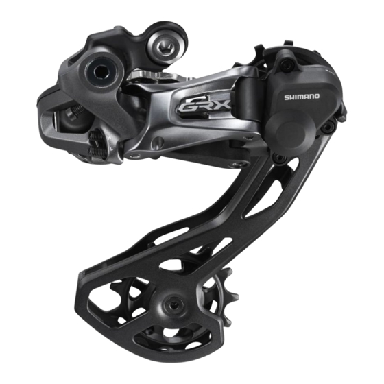
SHIMANO GRX
ST-RX815
FD-RX815
RD-RX815
RD-RX817
SHIMANO
SW-R9150
SM-EW90-A
SM-EW90-B
EW-RS910
EW-WU111
EW-SD50
EW-SD50-I
EW-JC130
MTB
URBAN SPORT
RX815 series
SM-EWC2
SM-JC40
SM-JC41
SM-BTR1
BT-DN110
BT-DN110-A
BM-DN100
SM-BA01
SM-BCR1
SM-BCR2
SM-BCC1
Dealer's Manual
Trekking
E-BIKE
DM-RX815-00
Advertisement
Table of Contents


Need help?
Do you have a question about the GRX RX 815 Series and is the answer not in the manual?
Questions and answers