
Related Manuals for Leuze electronic SOLID-2SF-M


Summary of Contents for Leuze electronic SOLID-2SF-M
- Page 1 Original operating instructions SOLID-2SF-M Optoelectronic delivery guarding for sheet fed offset printing machines CONNECTING AND OPERATING INSTRUCTIONS We reserve the right to make technical changes EN 2020/10/29 - 604058...
- Page 2 © 2020 Leuze electronic GmbH + Co. KG In der Braike 1 D-73277 Owen / Germany Phone: +49 7021 573-0 Fax: +49 7021 573-199 http://www.leuze.com info@leuze.de Leuze electronic GmbH + Co. KG SOLID-2SF-M...
-
Page 3: Table Of Contents
Dimensions, weights ............25 Leuze electronic GmbH + Co. KG... - Page 4 10.5 EC Declaration of Conformity ........... . 33 Leuze electronic GmbH + Co. KG...
-
Page 5: General Information
Certifications The company Leuze electronic GmbH & Co. KG in D-73277 Owen/Teck, possesses a certified quality assurance system in accordance with ISO 9001. Products The SOLID-2SF safety light curtains have been developed and manufactured in accordance with the appli- cable European directives and international standards. - Page 6 The receiver's active protective field is free; outputs in ON state The receiver's active protective field is free; outputs in OFF state Signal output Signal input Signal input and/or output Table 1.1: Symbols Leuze electronic GmbH + Co. KG SOLID-2SF-M...
- Page 7 Contactor monitoring The contactor monitoring (External Device Monitoring) monitors the normally (EDM) closed contacts of downstream positive-guided relays and contactors or valves Factory setting Table 1.2: Terms Leuze electronic GmbH + Co. KG SOLID-2SF-M...
-
Page 8: Safety
(see table 2.1). For mounting, operating and testing, document "SOLID-2SF-M, Optoelectronic delivery guarding of sheet-fed printing machines" as well as all applicable national and international standards, regulations, rules and directives must be observed. -
Page 9: Intended Use
When selecting the safety sensor it must be ensured that its safety-related capability meets or exceeds the required Performance Level PL ascertained in the risk assessment. Listed in the following table are the safety-related characteristic parameters of the SOLID-2SF-M optoelec- tronic delivery guarding for sheet-fed printing machines. Type in accordance with IEC/EN 61496... -
Page 10: Responsibility For Safety
• Adhering to all regulations and directives for labor protection and safety at work • Regular testing by competent personnel Exemption of liability Leuze electronic GmbH + Co. KG is not liable in the following cases: • Safety sensor is not used as intended. • Safety notices are not adhered to. -
Page 11: System Design And Selectable Functions
AOPD "A" transmission channel 1 AOPD "B" transmission channel 2, not affected by AOPD "A" Figure 3.2: Transmission channel selection (AOPD = Active Optoelectronic Protective Device) Leuze electronic GmbH + Co. KG SOLID-2SF-M... - Page 12 The change from transmission channel 1 to 2 must be made both on the transmitter and the receiver of the optical protective device in question. Further details can be found in chapter 6. Leuze electronic GmbH + Co. KG SOLID-2SF-M...
-
Page 13: Display Elements
Device error Table 4.1: LED operation indicators, transmitter Operation indicators on the receiver LED1 and the 7-segment display signal the operating states of the receiver. LED1 = red/green Figure 4.2: Operation indicators, receiver Leuze electronic GmbH + Co. KG SOLID-2SF-M... -
Page 14: 7-Segment Display
= At least one safety output SSD in OFF state green Green = All safety outputs SSDs in the ON state No display = Device without supply voltage Table 4.4: LED indicators at the receiver Leuze electronic GmbH + Co. KG SOLID-2SF-M... -
Page 15: Mounting
The minimum distance "a" depends on the distance "b" between transmitter and receiver. 4°± 4°± a = Minimum distance b = Protective field width c = Reflective surface Figure 5.1: Minimum distances to reflective surfaces Leuze electronic GmbH + Co. KG SOLID-2SF-M... -
Page 16: Mechanical Fastening
Additional access points must be secured separately (e.g., by hard guards, additional safety light curtains or doors with interlock devices). Types of fastening 5.5.1 Standard fastening Straddle brackets (for transmitter and receiver each) are included in delivery. Figure 5.3: Clamp bracket for C-groove mounting Leuze electronic GmbH + Co. KG SOLID-2SF-M... -
Page 17: Fastening Via Swiveling Mounting Brackets
Optionally, mounting is possible with mounting brackets and sliding blocks on the lateral groove. They are not included in the scope of delivery. L mounting bracket Z mounting bracket Figure 5.5: Mounting examples, L mounting bracket and Z mounting bracket Leuze electronic GmbH + Co. KG SOLID-2SF-M... -
Page 18: Electrical Connection
Be sure to select the same transmission channel for both, transmitter and receiver. ATTENTION! For optimum shielding, connection cables where the shield is routed on the knurled nut of the housing connector must be used (suitable cables are listed under accessories in chapter 9.3). Leuze electronic GmbH + Co. KG SOLID-2SF-M... -
Page 19: Testing
= External test signal b = High-impedance or 0 V Figure 6.2: SOLID-2SF external testing 6.1.3 Receiver White Brown Green Yellow Gray Pink Blue Black Figure 6.3: 8-pin SD-2R (view of the pins) Leuze electronic GmbH + Co. KG SOLID-2SF-M... - Page 20 300 ms pulse width. This dynamic signal must be moni- tored by the downstream control. If the Dyn SSD signal remains static, the power-driven machinery must be switched off. Correct connection must be checked with the machine's initial commissioning! Leuze electronic GmbH + Co. KG SOLID-2SF-M...
-
Page 21: Error Diagnostics
Check/replace power supply unit or load E 18 Test time limit exceeded Test time > 150 ms; check external testing E 22 Overvoltage at the supply line Check power supply unit/load Table 7.2: Receiver diagnosis Leuze electronic GmbH + Co. KG SOLID-2SF-M... -
Page 22: Autoreset
• approx. 2 seconds for the transmitter • approx. 20 seconds for the receiver for the device in question. If the error or fault is then no longer present, the machine or system can be started again. Leuze electronic GmbH + Co. KG SOLID-2SF-M... -
Page 23: Technical Data
EN 60825-1:1994+ A1:2002+A2001: Class: Wavelength: 950 nm Pulse duration: 7 µs Pulse pause: 3.1 ms Power: < 10µW Synchronization Optical between transmitter and receiver Test repeat time for integrated cyclical 300 ms test Leuze electronic GmbH + Co. KG SOLID-2SF-M... -
Page 24: Signal Input Transmitter
Dyn SSD switching frequency 3.3 Hz (300 ms pulse width) +/-10% Dyn SSD signal delay after switch-on/ 3 sec autoreset Note the additional restrictions due to cable length and load current Table 8.4: Transistor outputs, receiver Leuze electronic GmbH + Co. KG SOLID-2SF-M... -
Page 25: Dimensions, Weights
2-beam: 216,5 30,8 175,25 min.170 / max.400 3-beam: 216,5 30,8 30,830,8 175,25 min.190 / max.420 min. 170 / max.400 4-beam: 379,25 216,5 124,2 30,8 30,8 16,25 min.190 / max.420 min.170 / max.400 175,25 Leuze electronic GmbH + Co. KG SOLID-2SF-M... -
Page 26: Dimensions Mounting Bracket
Technical data 8.2.2 Dimensions mounting bracket Figure 8.1: Clamp bracket for C-groove mounting Figure 8.2: Option: swiveling mounting bracket with shock absorber Figure 8.3: Option: L mounting bracket Leuze electronic GmbH + Co. KG SOLID-2SF-M... - Page 27 Technical data Figure 8.4: Option: Z mounting bracket Leuze electronic GmbH + Co. KG SOLID-2SF-M...
-
Page 28: Ordering Data
BT-SSD mounting bracket set, consisting of 2x BT-SSD 429059 BT-SSD/SET of 4 BT-SSD mounting bracket set, consisting of 4x BT-SSD 429049 BT-SSD-270/SET of 2 BT-SSD-270 mounting set, consisting of 2x BT-SSD-270 mounting brackets Leuze electronic GmbH + Co. KG SOLID-2SF-M... - Page 29 Connection cable, shielded, with M12 connection, angled, length 10 m 429085 CB-M12-15000S-8GF Connection cable, shielded, with M12 connection, straight, length 15 m 429086 CB-M12-15000S-8WF Connection cable, shielded, with M12 connection, angled, length 15 m Table 9.1: Accessories SOLID-2SF Leuze electronic GmbH + Co. KG SOLID-2SF-M...
-
Page 30: Tests
You must have the effectiveness of the protective device checked by an qualified personnel at suitable intervals, but at least once a year. The applicable checklist in the Appendix may also be used during regular testing. Leuze also provides a specialist service for regular tests. Leuze electronic GmbH + Co. KG SOLID-2SF-M... -
Page 31: Daily Testing With The Test Rod
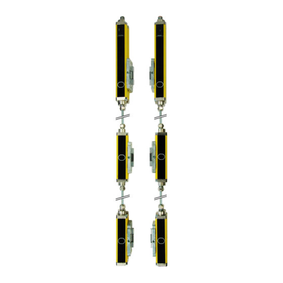
Figure 10.1: Testing with the test rod LED1 of the receiver must be observed during the testing procedure. If a light beam is interrupted by the test rod, LED1 must change from "green" to "red". Leuze electronic GmbH + Co. KG SOLID-2SF-M... -
Page 32: Checklists
When the AOPD is separated from its supply voltage, does the dangerous movement stop, and, after the supply voltage has been restored, is it necessary to actuate the start/restart button to reset the machine? Leuze electronic GmbH + Co. KG SOLID-2SF-M... -
Page 33: Ec Declaration Of Conformity
Tests 10.5 EC Declaration of Conformity You can download this EC Declaration of Conformity from the Internet: http://www.leuze.de/solid Leuze electronic GmbH + Co. KG SOLID-2SF-M...