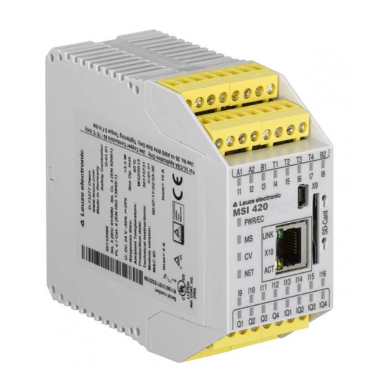
Summary of Contents for Leuze electronic MSI 420.TMC-03
- Page 1 MSI 420.TMC-03 TMC 66 Legacy S A F E I M P L E M E N T A T I O N A N D O P E R A T I O N O r i g i n a l o p e r a t i n g i n s t r u c t i o n s...
- Page 2 Exemption of liability Leuze electronic GmbH + Co. KG is not liable in the following cases: • Safety relay is not used as intended. • Safety notices are not adhered to. • Reasonably foreseeable misuse is not taken into account.
-
Page 3: Table Of Contents
EU/EC Declaration of Conformity........17 Leuze electronic MSI 420.TMC-03... -
Page 4: About This Document
About this document This document is a translation of the original operating instructions for the product MSI 420.TMC-03. It describes handling of the discontinued TMC 66 (Leuze article no. 50082121) and how to replace the TMC TMC 66 Legacy 66 for the substitute MSI 420.TMC-03. The latter is also referred to below as the solution. -
Page 5: System Overview
System overview TMC 66 Legacy system is based on the MSI 400 safe compact control from Leuze electronic. The system is a substitute for the TMC 66 (Leuze electronic article no. 50082121) and is used only as a replacement solution. NOTE During development of the replacement solution, great importance was placed on 1:1 exchangeability (wiring and functionality) with the TMC 66. -
Page 6: System Limits
When the safety distance as defined in ISO 13855 and required for the respective application is calculated, a total reaction time of 35.6 ms must be factored in for the response time of the MSI 420.TMC-03 (MSI 400 hardware + software functionality). -
Page 7: Description Of Functions
The OSSDs of the MSI 420.TMC-03 remain in the ON state in spite of interruption of the protective sensor. Arrangement of the muting sensors Muting sensors detect the transport material and supply the signals necessary for muting. -
Page 8: Muting Phases
If tR is exceeded, muting is not initiated and an error message is output (see chapter 5 "Diagnostics messages"). Danger zone Protective sensor Start 1 Start 2 Figure 3.1: Phase 1 - Muting preparation is activated by applying the control signals. The pallet is still completely inside the danger zone. Leuze electronic MSI 420.TMC-03... - Page 9 Start 2 Figure 3.4: Phase 4 - Continuation of the muting process with occupancy of Start 2 by the pallet. A maximum time between occupancy of Start 1 and Start 2 is not monitored by the device. Leuze electronic MSI 420.TMC-03...
- Page 10 Phase 6 - Protective sensor becomes free Muting still remains active after the transport material releases the protective sensor again. Danger zone Protective sensor Start 1 Start 2 Figure 3.6: Phase 6 - Protective sensor becomes free again. Leuze electronic MSI 420.TMC-03...
-
Page 11: Override - Starting System With Occupied Protective Sensor
• Control 2 signal set to LOW potential • Start 1 IN signal set to HIGH potential • Start 2 IN signal set to HIGH potential Muting can then be restarted by activating the two control signals. Leuze electronic MSI 420.TMC-03... -
Page 12: Electrical Connection And Commissioning
Lay the cables and lines so that they are protected against external damages. For further information: see EN ISO 13849-2, Table D.4. Step 1: Replace the defective TMC 66 with the MSI 420.TMC-03 The table below shows the wiring for the existing signals. - Page 13 4.2 "Selection of operat- ing mode" Figure 4.1: Connection example for MSI 420.TMC-03 with start/restart interlock and contactor monitor- ing (operating mode 3) Step 2: Selection of operating mode To select the desired operating mode, install the corresponding wire bridges as specified in table 4.2. In the delivery state, no wire bridges are installed, hence operating mode 1 is configured.
- Page 14 Step 4: Apply supply voltage Switch on the supply voltage of the MSI 420.TMC-03 and wait until the control has performed the self test (approx. 5 seconds). The following indicators now light up on the front of the MSI 400: PWR/EC LED: green The voltage supply is between 16.8 V and 30 V.
- Page 15 Were distances to reflective surfaces taken into account during configura- tion and no reflection bypasses subsequently detected? Are notices for regular testing of the safety sensor legible to the operator and are they located in a highly visible location? Leuze electronic MSI 420.TMC-03...
- Page 16 Are there incentives that pose stimulus for tampering? Were the operators instructed prior to starting work? If errors occur during the test/function check, please contact our hotline (see chapter 7 "Service and support"). Leuze electronic MSI 420.TMC-03...
-
Page 17: Diagnostics Messages
LED assigned to the input. The LED stops flashing as soon as the error has been corrected. In addition, three outputs of the MSI 420.TMC-03 are used for error diagnostics. Safety on (output IQ2) - The signal output is active whenever the safety outputs of the MSI 420.TMC-03 are carrying a HIGH signal. -
Page 18: Maintenance
Do not attempt to remove, repair or modify the MSI 400 modules. This can lead to the loss of the safety function(s). Furthermore, all warranty claims against Leuze electronic GmbH will be void. Regular checks on protective device by competent persons ... -
Page 19: Eu/Ec Declaration Of Conformity
EU/EC Declaration of Conformity Leuze electronic MSI 420.TMC-03... - Page 20 Leuze electronic MSI 420.TMC-03...


Need help?
Do you have a question about the MSI 420.TMC-03 and is the answer not in the manual?
Questions and answers