Sign In
Upload
Manuals
Brands
ST Manuals
Motherboard
AEK-MOT-TK200G1
ST AEK-MOT-TK200G1 Manuals
Manuals and User Guides for ST AEK-MOT-TK200G1. We have
1
ST AEK-MOT-TK200G1 manual available for free PDF download: User Manual
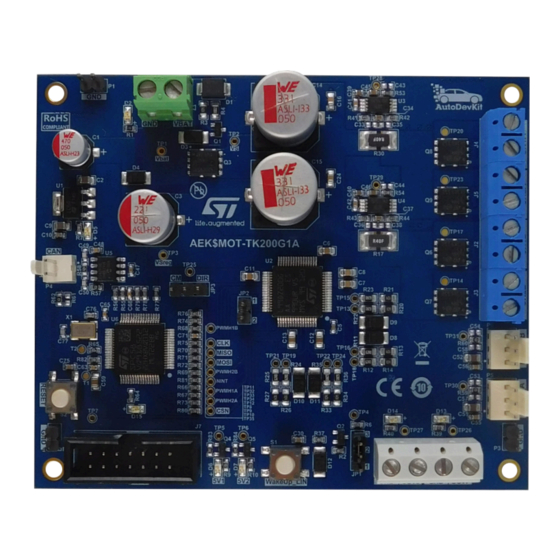
ST AEK-MOT-TK200G1 User Manual (47 pages)
evaluation board for car opening/closing systems
Brand:
ST
| Category:
Motherboard
| Size: 2 MB
Table of Contents
Figure 1. AEK-MOT-TK200G1 Evaluation Board
1
Hardware Overview
2
Board Main Components
2
Spc582B60E1
2
Figure 2. AEK-MOT-TK200G1 Evaluation Board: Main Components
2
L99Dz200G
3
Current Sensing Monitoring Network
4
Figure 3. TSC103 Current Sense Amplifier
4
CAN Connector and Potentiometer Connectors
5
Table 1. Specifications of the L12-50-100-12-P Actuonix DC Motor
5
Figure 4. TSC103 Current Sense Amplifier
5
L99DZ200G State Machine
6
Figure 5. Simplified L99DZ200G FSM
6
Watchdog Scheme
7
Figure 6. Watchdog Timing 1
7
Software Overview
8
Low-Level Drivers
8
Figure 7. Software Architecture
8
Figure 8. Low-Level Drivers
8
Aek_Mot_Tk200G1_Api
9
Figure 9. API Architecture
9
Figure 10. Update Register Function
10
Figure 11. Wrapper Functions
10
Safety Mechanism: Watchdog Trigger
11
Figure 12. Sel_Mot_Tk200G1_Init() Function
11
AEK-MOT-TK200G1 in Autodevkit
12
Autodevkit Ecosystem
12
Spc5-Studio
12
Stsw-Autodevkit
12
How to Download Demos from Spc5Studio and Autodevkit
12
How to Locate the AEK-MOT-TK200G1 SW Library in the Demo
13
Figure 13. Import Sample from Application Library
13
Figure 14. MCU and Demo Selection
13
How to Configure the Low-Level Drivers
14
Figure 15. Code Generation
14
Figure 16. Driver Folders
14
SPI Configuration
15
Figure 17. Enabling Low-Level Drivers
15
Figure 18. SPI Selection
15
Figure 19. SPI Configuration List
16
Figure 20. SPI Transfer Configuration
16
Figure 21. SPI Timing Configuration
17
Programmable Interrupt Timer (PIT) Configuration
18
PWM Configuration
18
Figure 22. SPI Chip Selection
18
Figure 23. PIT Configuration
18
How to Execute SW Debug for the AEK-MOT-TK200G1
19
Figure 24. PWM Configuration (1 of 3)
19
Figure 25. PWM Configuration (2 of 3)
19
Figure 26. PWM Configuration (3 of 3)
19
Figure 27. Debug Input Mode: Jumper Positioning
20
Figure 28. Debug Input Mode: Powering the Board
20
Figure 29. Debug Input Mode: Powering the Board
21
Available Demos for the AEK-MOT-TK200G1
22
Spc582Bxx_Rla_Aek-MOT-Tk200G1_Motorcontrol - Test Application for Discovery
22
Spc58Ecxx_Rla_Mainecufor_Aek-MOT-Tk200G1Control - Test Application
22
Available Apis
24
Table 2. Available Apis for the AEK-MOT-TK200G1
24
How to Customize the Current Sensing Network
26
Figure 30. ADC Reference Voltage
26
Motor Model Used During the AEK-MOT-TK200G1 Emission Tests
28
Table 3. Motor Specifications
28
Schematic Diagrams
29
Figure 31. AEK-MOT-TK200G1 Circuit Schematic (1 of 5)
29
Figure 32. AEK-MOT-TK200G1 Circuit Schematic (2 of 5)
30
Figure 33. AEK-MOT-TK200G1 Circuit Schematic (3 of 5)
31
Figure 34. AEK-MOT-TK200G1 Circuit Schematic (4 of 5)
32
Figure 35. AEK-MOT-TK200G1 Circuit Schematic (5 of 5)
33
Bill of Materials
34
Table 4. AEK-MOT-TK200G1 Bill of Materials
34
Board Versions
40
Table 5. AEK-MOT-TK200G1 Versions
40
Regulatory Compliance Information
41
Table 6. Document Revision History
42
Advertisement
Advertisement
Related Products
ST AEK-MOT-WINH92
ST AEKD-USBTYPEC1
ST AEK-SNS-2TOFM1
ST AEKD-AICAR1
ST AEK-POW-LDOV01J
ST AEK-POW-LDOV01S
ST AEK-POW-BMSLV
ST AutoDevKit AEK-POW-BMS63EN
ST AEK-COM-10BASET
ST ARMIC30
ST Categories
Motherboard
Computer Hardware
Microcontrollers
Control Unit
Controller
More ST Manuals
Login
Sign In
OR
Sign in with Facebook
Sign in with Google
Upload manual
Upload from disk
Upload from URL