
Subscribe to Our Youtube Channel
Related Manuals for Rohde & Schwarz FS-K30


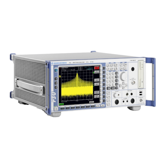
Summary of Contents for Rohde & Schwarz FS-K30
- Page 1 R&S FS-K30 ® Application Firmware for Noise Figure and Gain Measurments for R&S Analyzers ® Software Manual 1300.6637.42 – 03...
- Page 2 Printed in Germany – Subject to change – Data without tolerance limits is not binding. ® R&S is a registered trademark of Rohde & Schwarz GmbH & Co. KG. Trade names are trademarks of the owners. The following abbreviations are used throughout this manual: ® R&S FS-K30 is abbreviated as R&S FS-K30.
- Page 3 Basic Safety Instructions Always read through and comply with the following safety instructions! All plants and locations of the Rohde & Schwarz group of companies make every effort to keep the safety standards of our products up to date and to offer our customers the highest possible degree of safety. Our products and the auxiliary equipment they require are designed, built and tested in accordance with the safety standards that apply in each case.
- Page 4 Basic Safety Instructions Tags and their meaning The following signal words are used in the product documentation in order to warn the reader about risks and dangers. indicates a hazardous situation which, if not avoided, will result in death or serious injury.
- Page 5 Basic Safety Instructions Electrical safety If the information on electrical safety is not observed either at all to the extent necessary, electric shock, fire and/or serious personal injury or death may occur. 1. Prior to switching on the product, always ensure that the nominal voltage setting on the product matches the nominal voltage of the AC supply network.
- Page 6 Basic Safety Instructions 14. Use suitable overvoltage protection to ensure that no overvoltage (such as that caused by a bolt of lightning) can reach the product. Otherwise, the person operating the product will be exposed to the danger of an electric shock. 15.
- Page 7 Basic Safety Instructions Repair and service 1. The product may be opened only by authorized, specially trained personnel. Before any work is performed on the product or before the product is opened, it must be disconnected from the AC supply network.
- Page 8 Informaciones elementales de seguridad 2. Handles on the products are designed exclusively to enable personnel to transport the product. It is therefore not permissible to use handles to fasten the product to or on transport equipment such as cranes, fork lifts, wagons, etc. The user is responsible for securely fastening the products to or on the means of transport or lifting.
- Page 9 Informaciones elementales de seguridad Se parte del uso correcto del producto para los fines definidos si el producto es utilizado conforme a las indicaciones de la correspondiente documentación del producto y dentro del margen de rendimiento definido (ver hoja de datos, documentación, informaciones de seguridad que siguen). El uso del producto hace necesarios conocimientos técnicos y ciertos conocimientos del idioma inglés.
- Page 10 Informaciones elementales de seguridad Palabras de señal y su significado En la documentación del producto se utilizan las siguientes palabras de señal con el fin de advertir contra riesgos y peligros. PELIGRO identifica un peligro inminente con riesgo elevado que provocará...
- Page 11 Informaciones elementales de seguridad Seguridad eléctrica Si no se siguen (o se siguen de modo insuficiente) las indicaciones del fabricante en cuanto a seguridad eléctrica, pueden producirse choques eléctricos, incendios y/o lesiones graves con posible consecuencia de muerte. 1. Antes de la puesta en marcha del producto se deberá comprobar siempre que la tensión preseleccionada en el producto coincida con la de la red de alimentación eléctrica.
- Page 12 Informaciones elementales de seguridad 12. Si un producto se instala en un lugar fijo, se deberá primero conectar el conductor de protección fijo con el conductor de protección del producto antes de hacer cualquier otra conexión. La instalación y la conexión deberán ser efectuadas por un electricista especializado. 13.
- Page 13 Informaciones elementales de seguridad 5. Ciertos productos, como p. ej. las instalaciones de radiocomunicación RF, pueden a causa de su función natural, emitir una radiación electromagnética aumentada. Deben tomarse todas las medidas necesarias para la protección de las mujeres embarazadas. También las personas con marcapasos pueden correr peligro a causa de la radiación electromagnética.
- Page 14 Informaciones elementales de seguridad 6. En caso de falta de estanqueidad de una celda, el líquido vertido no debe entrar en contacto con la piel ni los ojos. Si se produce contacto, lavar con agua abundante la zona afectada y avisar a un médico.
- Page 15 Qualitätszertifikat Certified Quality System ISO 9001 Certificate of quality Certified Environmental System Certificat de qualité ISO 14001 Sehr geehrter Kunde, Dear Customer, Cher client, Sie haben sich für den Kauf eines You have decided to buy a Vous avez choisi d’acheter un pro- Rohde &...
- Page 16 Customer Support Technical support – where and when you need it For quick, expert help with any Rohde & Schwarz equipment, contact one of our Customer Support Centers. A team of highly qualified engineers provides telephone support and will work with you to find a solution to your query on any aspect of the operation, programming or applications of Rohde &...
-
Page 17: Table Of Contents
R&S FS-K30 Table of Contents Table of Contents Conventions Used in the Documentation......... 7 1 General Information................9 Introduction to R&S FS-K30 & Noise Measurements..........9 Installation ........................10 Starting the application .....................11 Exiting the application ....................11 Quick Start Guide.......................12 1.5.1 Setting up the measurement..................12 1.5.1.1... - Page 18 R&S FS-K30 Table of Contents Limit Line ........................34 1.9.1 Adding Limit Lines......................35 1.9.1.1 Name ...........................35 1.9.1.2 Limit ..........................36 1.9.1.3 Comment ........................36 1.9.1.4 Frequency / Limit Table ....................36 1.9.2 Modifying Limit Lines ....................37 1.9.3 Deleting Limit Lines......................38 1.9.4 Enabling / disabling Limit Lines ...................38 1.10...
- Page 19 R&S FS-K30 Table of Contents 2.4.1.7 Image Rejection ......................56 2.4.1.8 Single Frequency Measurement..................57 2.4.2 Frequency Table ......................57 2.4.3 Schematic Diagrams....................58 Measurement Settings ....................59 2.5.2 Calibration........................60 2.5.2.1 2nd Stage Correction ....................60 2.5.3 Analyzer Settings ......................60 2.5.3.1 RBW..........................60 2.5.3.2 Sweep Time .........................61 2.5.3.3...
- Page 20 R&S FS-K30 Table of Contents Loss Settings ......................72 2.7.2 Loss Settings – Loss Input Settings................72 2.7.2.1 Selection ........................73 2.7.2.2 Loss Input Constant .....................73 2.7.3 Loss Input Table ......................73 2.7.4 Loss Settings – Loss Output Settings................75 2.7.4.1 Selection ........................75 2.7.4.2 Loss Output Constant ....................75 2.7.5...
- Page 21 R&S FS-K30 Table of Contents 3 Remote Control ................. 88 Description of commands..................88 3.1.1 Notation........................88 3.1.2 ABORt Subsystem .......................90 3.1.3 CALCulate: Subsystem....................91 3.1.3.1 CALCulate:LIMit Subsystem..................91 3.1.3.2 CALCulate:LIMit:CONTrol Subsystem.................94 3.1.3.3 CALCulate:LIMit:LOWer Subsystem ................95 3.1.3.4 CALCulate:LIMit:UPPer Subsystem ................96 3.1.4 CALCulate:MARKer Subsystem ..................98 3.1.5...
-
Page 23: Conventions Used In The Documentation
R&S FS-K30 Conventions Used in the Documentation Conventions Used in the Documentation The following conventions are used throughout the R&S FS-K30 Software Manual: Typographical conventions Convention Description “Graphical user interface elements” All names of graphical user interface elements both on the screen and on the front and rear panels, such as dialog boxes, softkeys, menus, options, buttons etc., are enclosed by quotation marks. -
Page 25: General Information
For the user wanting to make a quick start to using R&S FS-K30, the Quick Start Guide section below works step-by-step through an ordinary noise figure measurement. The remainder of this section describes all of the basic information about how the R&S FS-... -
Page 26: Installation
7. When the analyzer starts after the reboot a new hotkey will be displayed at the bottom of the display labelled NOISE. In addition an entry for the R&S FS-K30 option will be displayed in the FIRMWARE OPTIONS dialog. -
Page 27: Starting The Application
Note that if the spectrum analyzer is powered down whilst R&S FS-K30 is active, then when the spectrum analyzer is powered up again it will start up in the R&S FS-K30 application. The application will start up with the same settings as those at the end of the last measurement. -
Page 28: Quick Start Guide
General Information Quick Start Guide 1.5 Quick Start Guide This section helps the user to quickly become familiar with R&S FS-K30 by working step-by-step through an ordinary noise figure measurement. (Refer to section 2 for a detailed reference guide.) The gain and noise figure of an amplifier are to be determined in the range from 220 MHz to 320 MHz. - Page 29 The manufacturer of the noise source supplies these sampled values. For the purposes of this introduction to R&S FS-K30, it is sufficient to specify a constant ENR value for this measurement. The default Selection for ENR is a Constant value for all frequencies, so this does not need to be changed.
-
Page 30: Performing Calibration
R&S FS-K30 General Information Quick Start Guide 6. Press the SET MEAS softkey to open the Measurement Settings view In order to perform measurements as accurately as possible the Second Stage Correction field needs to be set. This specifies that a separate calibration measurement is to be performed before the main measurement. -
Page 31: Performing The Amplifier Measurement
1. Set the Second Stage Correction parameter in the Measurement Setting view to ON. Calibration cannot be performed until this parameter is set. 2. Start the calibration of R&S FS-K30 by pressing the CAL hotkey. During calibration, the text "Running ..." is displayed in the Status Bar at the bottom of the screen. -
Page 32: Navigation
R&S FS-K30 General Information Navigation 1. Start the measurement by pressing the RUN SGL hotkey. During the measurement, the text "Running..." is displayed in the Status Bar at the bottom of the screen. The progress bar indicates the progress through the measurement. - Page 33 R&S FS-K30 General Information Navigation These hotkeys perform the following operations: The SPECTRUM hotkey exits the R&S FS-K30 option & returns to the spectrum SPECTRUM analyzer with all previous settings restored. NOISE The NOISE hotkey returns the user to the home screen of K30, where measurement results can be seen.
-
Page 34: Softkeys
R&S FS-K30 General Information Navigation 1.6.2 Softkeys 1.6.2.1 Settings Softkeys The softkeys are assigned to the nine keys on the right-hand side of the display. These enable quick access to all of the parameter settings of the K30 option. Each of the top five softkeys, when pressed, brings up a settings view for a group of parameters. -
Page 35: Other Softkeys
R&S FS-K30 General Information Navigation 1.6.2.2 Other Softkeys All other softkeys have different functions depending on the instrument state. Therefore, the labels (text) on the softkeys will vary to reflect their current function. The state of the softkeys is indicated by different appearances and colours, as follows:... -
Page 36: Hardkeys
Navigation 1.6.3 Hardkeys Hardkeys allow quick access to the desired parameter and various functions. The hardkeys supported by the R&S FS-K30 option are as follows (other hardkeys do nothing): FREQ Hardkey When the FREQ hardkey is pressed the General Settings view is displayed (if it is not already being displayed) and the Frequency parameter is selected. -
Page 37: External Keyboard
R&S FS-K30 General Information Navigation 1.6.4 External Keyboard The external keyboard is optional. The keys on the external keyboard that can be used to interact with the K30 option are as follows: Number keys 0 to 9 Decimal point (“.”) Inserts a decimal point “.”... -
Page 38: Mouse
R&S FS-K30 General Information Navigation 1.6.5 Mouse The mouse can be used to select individual parameters within the settings views or data entry dialogs and to activate hotkeys and softkeys. It can also be used to select values from a drop-down list. -
Page 39: Rollkey
R&S FS-K30 General Information Navigation Provides the numeric value entered with the selected unit and sets the parameter to that value. The unit keys are all assigned the value “1” for dimensionless quantities or for level entries (e.g. in dB). The unit keys thus assume the function of an ENTER key. -
Page 40: Cursor Keys
R&S FS-K30 General Information Navigation 1.6.6.3 Cursor Keys The keys are used to: Navigate between individual parameters within the setting views and some of the pop-up dialogs. Navigate between the individual values within drop-down menus. Move the cursor left & right inside the entry window to reach a particular position in the string during alphanumeric entry. - Page 41 R&S FS-K30 General Information Navigation Selection using cursor keys 1. Cursor until obtaining the required parameter. Within a list of parameters, the Down and Right both move to the next item (down) in the list and the Up and Left keys both move to the previous item (up) in the list.
- Page 42 R&S FS-K30 General Information Navigation Entry of a numeric value Once a parameter has been selected (see above), a new value for a numeric parameter can be entered in a number of ways. With the exception of entry via the number keys, to start editing the parameter, either press the ENTER key on the numeric keypad, or press the rollkey before following the instructions below.
- Page 43 R&S FS-K30 General Information Navigation Entry using rollkey 1. Rotate the rollkey until reaching the required value. 2. Turning the rollkey clockwise increases the value, turning it counter clockwise decreases the value. The application prevents the minimum and maximum values of the parameter from being exceeded and displays an “Out of range“...
-
Page 44: Entry Of An Enumerated Value
R&S FS-K30 General Information Navigation Correcting the entry 1. Position the cursor to the right of the digit which is to be deleted using the cursor keys 2. Press the BACK key. The digit to the left of the cursor is deleted. -
Page 45: Entry Of A Checkbox
R&S FS-K30 General Information Navigation Selection of setting using mouse N When the parameter is selected and ready for editing, select a new setting using the mouse by left-clicking on the new setting from the drop-down list. The new setting of the parameter is set immediately. - Page 46 1.6.6.7 Table Navigation In R&S FS-K30 some of the settings views contain tables of data (for example the frequency table in the Frequency Settings view). Initially when navigating through the settings in a view only the header of a table can be selected Selecting &...
-
Page 47: Status Bar & Title Bar
Navigation 1.6.7 Status Bar & Title Bar 1.6.7.1 Title Bar The title bar is visible at the very top of the display when R&S FS-K30 is active and no settings views are displayed. Fig. 8 Title Bar The centre of the title bar shows the name of the active application. For R&S FS-K30, this is “NOISE &... -
Page 48: Save/Recall
Figure 10 Save/Recall softkey menu The save/recall facility provided by R&S FS-K30 is exactly the same as that provided by the host analyser. Refer to the user manual for the spectrum analyser for details of the save/recall facility operation. -
Page 49: Printing
Fig. 11: Print softkey menu The print facility provided by FS-K30 is exactly the same as that provided by the host analyser. Refer to the user manual for the spectrum analyser for details of the print facility operation. -
Page 50: Limit Line
R&S FS-K30 General Information Limit Line 1.9 Limit Line This section of the user manual describes limit line facility of the option. The LINES hardkey brings up Limit Line selection view and softkey menu. Any settings views on display when the limit lines selection view is displayed shall be closed. -
Page 51: Adding Limit Lines
R&S FS-K30 General Information Limit Line 1.9.1 Adding Limit Lines New limit lines can be defined by pressing the NEW softkey from the limit line selection softkey menu. The NEW softkey allows a new limit line to be defined. After pressing the NEW softkey the limit line selection view will be replaced with the limit line data view. -
Page 52: Limit
Frequency / Limit Table The Frequency/Limit Table lists the Limit values for different Receive Frequency (RF) values. R&S FS-K30 will interpolate between points in the list for RF values used in a measurement that are not explicitly entered in the Frequency/Limit list. -
Page 53: Modifying Limit Lines
R&S FS-K30 General Information Limit Line DELETE The DELETE softkey deletes the currently selected row in the Limit Table. Note that no confirmation is required for this action. The cursor will be moved to the corresponding column in the next row. -
Page 54: Deleting Limit Lines
R&S FS-K30 General Information Limit Line 1.9.3 Deleting Limit Lines Existing limit lines can be deleted by pressing the DELETE softkey from the limit line selection softkey menu The DELETE softkey allows the limit line selected in the limit line selection view to be deleted. -
Page 55: Trace Menu
This facility is recommended in order to graphically compare and document the effects of small changes on the DUT. In addition to the current measurement results, R&S FS-K30 can store and display up to 3 sets of trace memory results. DATA ->MEM The DATA->MEM softkeys (1,2 &... - Page 56 R&S FS-K30 General Information Trace Menu SHOW DATA ON/OFF The SHOW DATA softkey is used to toggle the display of the current measurement results traces on and off. The display of trace memory results is not affected when this softkey is pressed.
-
Page 57: Marker Menu
This section of the user manual describes the Marker facility of the option. The markers are used for marking points on traces, reading out measurement results and for quickly selecting a display section. R&S FS-K30 provides one marker. From the marker menu it is possible to adjust the marker position. -
Page 58: Adjusting Markers
R&S FS-K30 General Information Marker Menu 1.11.1 Adjusting Markers The marker can be adjusted by pressing the marker softkey in the marker softkey menu. MARKER 1 The MARKER 1 softkeys displays the Marker 1 pop-up dialog. As soon as a field in the marker pop-up dialog is adjusted then the marker position in the trace will update, along with the results displayed for the marker. -
Page 59: Mkr-> Menu
R&S FS-K30 General Information MKR-> Menu 1.12 MKR-> Menu Fig. 21 MKR-> softkey menu PEAK The PEAK softkey sets the active marker to the peak of the trace. If no marker is active when MKR-> menu is called, MARKER 1 is automatically switched on and the peak search is performed. -
Page 60: Measurements & Settings
The Measurement Mode can be selected in the Frequency Settings view by pressing the SET FREQ softkey. R&S FS-K30 also provides a schematic display of the test set-up for each of the above measurement modes. This provides a diagrammatic summary of the test set-up and frequency ranges. -
Page 61: Frequency-Converting Measurements
R&S FS-K30 Measurements & Settings Measurement modes & schematics Fig. 22 Schematic diagram for direct measurements 2.1.2 Frequency-converting measurements There are four types of frequency-converting measurements: two with a fixed intermediate frequency (IF) and two with a fixed Local Oscillator (LO) frequency. All have a similar test set-up (schematic) an example of which is shown below (the example shown is for a Fixed IF, LO = RF + IF measurement mode). -
Page 62: Calibration
When any change is made to the Frequencies List, that is, the list of Receive Frequencies (RF) at which measurements will be made, R&S FS-K30 will need to be calibrated again. This is necessary to ensure that there is calibration data available for every measurement step for the current measurement mode. - Page 63 3. Set the Second Stage Correction parameter in the Measurement Setting view to ON. Calibration cannot be performed until this parameter is set. 4. Start the calibration of R&S FS-K30 by pressing the CAL hotkey. During calibration, the text "Running..." is displayed in the Status Bar at the bottom of the screen.
-
Page 64: Running Measurements
Running measurements 2.2 Running measurements There are two forms of measurement that can be started by R&S FS-K30: Frequency List measurement – a measurement is performed at each of the frequencies listed in the frequency list (in the Frequency Settings view). A frequency list measurement can be run in one of two different modes (single or continuous). -
Page 65: Measurement Results
R&S FS-K30 Measurements & Settings Measurement results 2.3 Measurement results 2.3.1 Frequency List measurements After successful completion of a Frequency List measurement, the display will show either a graphical or list (tabular) view of the measurement results, depending on the currently selected view. - Page 66 R&S FS-K30 Measurements & Settings Measurement results Fig. 26 A typical tabular display of measurement results The tabular section below the title bar shows the overall measurement settings used for the last measurement. This includes the following: RBW: Resolution Bandwidth (Hz)
-
Page 67: Single Frequency Measurement
R&S FS-K30 Measurements & Settings Measurement results The bottom section of the table displays either a list or a graph of the complete set of points defined in the frequency list for the measurement. A graphical view will include either one or two traces. The Noise trace will be the same colour as Trace 1 in the spectrum analyzer (yellow by default) and the Gain trace will be the same colour as Trace 2 in the spectrum analyzer (blue by default). - Page 68 R&S FS-K30 Measurements & Settings Measurement results Fig. 27 Current Value area of table of results The left two columns display the settings being used for the measurement: RF: Receive Frequency at the DUT at which the current values were measured (Hz) LO: Local Oscillator frequency (Hz) –...
-
Page 69: Frequency Settings
CONT hotkey). This view allows the user to create the list of measurement steps in two ways: By entering values in the Frequency Settings group on the left (Start Frequency, Stop Frequency, Step Frequency, etc.), from which R&S FS-K30 will generate the list of measurement steps on the right. This allows rapid generation of a measurement consisting of up to 100 steps. -
Page 70: Frequency Settings
(but without losing the rest of the frequency range). Note that when any change is made to the Frequencies List, R&S FS-K30 will need to be calibrated again. -
Page 71: Stop Frequency
Mode selected. 2.4.1.4 Mode The measurement Mode should be selected according to the type of Device Under Test. R&S FS-K30 provides five different measurement Modes: Direct Fixed IF, LO = RF + IF Fixed IF, LO = abs(RF – IF) Fixed LO, IF = RF + LO Fixed LO, IF = abs(RF –... -
Page 72: Fixed Lo
R&S FS-K30 Measurements & Settings Frequency Settings 2.4.1.5 Fixed LO The Fixed LO is the fixed local oscillator frequency for measurement Modes. Fixed LO, IF = RF + LO Fixed LO, IF = abs(RF – LO) Changing the Fixed LO will replace all LO values in the Frequencies List (the list of measurement steps). -
Page 73: Single Frequency Measurement
R&S FS-K30 Measurements & Settings Frequency Settings The value entered is applied across the complete frequency range. The default value of 999.99 dB means that the second sideband does not noticeably affect the measurement result because a suppression of 999.99 dB is applied to it. This corresponds to the generally used single-sideband (SSB) measurement. -
Page 74: Schematic Diagrams
R&S FS-K30 Measurements & Settings Frequency Settings regenerated according to the start/stop/step frequencies and mode parameters at any time by pressing the BUILD TBL softkey When focus is moved to the frequency table navigation through the table is possible in all four directions using the cursor keys. -
Page 75: Measurement Settings
R&S FS-K30 Measurements & Settings Measurement Settings 2.5 Measurement Settings This section of the user manual describes the Measurement Settings view where all settings related to the overall measurement can be modified, that is the Calibration, Analyzer & Generator settings. -
Page 76: Calibration
Measurements & Settings Measurement Settings 2.5.2 Calibration Calibration of the R&S FS-K30 application measures the noise introduced to a signal by the spectrum analyzer itself. This can then be compensated for in measurements on a Device Under Test. This compensation is called 2nd Stage Correction, because the spectrum analyzer is the second stage of the test set-up, the DUT being the first stage. -
Page 77: Sweep Time
R&S FS-K30 Measurements & Settings Measurement Settings at low frequencies, the RBW must be reduced to prevent the LO frequency of the analyser from invalidating the measurement. At receive frequencies of 100 kHz, the RBW must not exceed 10 kHz. -
Page 78: Average
R&S FS-K30 Measurements & Settings Measurement Settings 2.5.3.4 Average The Average setting is the number of measurement sweeps over which the average is taken to produce the displayed measurement results. The higher the number of sweeps over which the Average is taken, the more accurate the measurement results will be and the more stable the display, but the measurement time will be significantly longer. -
Page 79: Ref Level
Measurements & Settings Measurement Settings When Automatic Ref Level is set to ON, R&S FS-K30 will measure the reference level automatically. This happens at one of two times: If 2nd Stage Correction is ON, then the reference level is determined and set at the start of the calibration measurement. -
Page 80: Pre-Selector
R&S FS-K30 Measurements & Settings Measurement Settings Range is the range of the DUT, that is, the maximum gain expected from the DUT. This value is used when Auto Ref Level is ON and 2nd Stage Correction is ON, to... -
Page 81: Pre-Amplifier (Electronic Attenuator)
Pre-selector field is switched OFF 2.5.4 Generator Settings R&S FS-K30 can be used to control an external signal generator in order to generate a Local Oscillator (LO) frequency for noise measurements on frequency-converting DUTs. This applies for the Measurement Modes: Fixed IF, LO = RF + IF Fixed IF, LO = abs(RF –... -
Page 82: Level
Fixed LO cases in which the signal generator settings do not need to change during the measurement. In the Fixed IF Measurement Modes, meaningful results will only be possible if Automatic Control is set to ON, since R&S FS-K30 will expect the LO frequency to be automatically tuned to the test RF frequency. -
Page 83: Init Before Meas
Note: The INIT GEN softkey in the main measurement results view and measurements settings view can be pressed to get R&S FS-K30 to send the initialisation sequence of GPIB commands to the signal generator at any time. -
Page 84: Enr Settings
ENR values of the noise source can be modified. It is essential for R&S FS-K30 to know the correct ENR values for the noise source in order to perform accurate measurements. The ENR values are used to calculate the effective noise temperature of the noise source and this is used during calculation of measurement results. -
Page 85: Enr Settings
ENR List will be ignored. When Selection is set to Table, R&S FS-K30 will use the Table of ENR values on the right of the view to calculate the ENR value to be used for each specific RF frequency at which a measurement is performed. - Page 86 R&S FS-K30 Measurements & Settings ENR Settings Fig. 32 ENR Table INSERT The INSERT softkey inserts a new row in the ENR Settings table directly above the row currently selected. The new row will contain zero values. The cursor will be moved to the corresponding column in the new row ready for detailed entry.
- Page 87 R&S FS-K30 Measurements & Settings ENR Settings DELETE The DELETE softkey deletes the currently selected row in the ENR Settings table. Note that no confirmation is required for this action. Software Manual 1300.6637.42 - 03...
-
Page 88: Loss Settings
R&S FS-K30 Measurements & Settings Loss Settings 2.7 Loss Settings This section of the user manual describes the Loss Settings view where the Loss values of the test setup can be modified. The Loss settings allow additional losses due to cables or attenuators to be taken into consideration in measurement results. -
Page 89: Selection
Loss Input List will be ignored. When Selection is set to Table, R&S FS-K30 will use the table of Loss Input values at the bottom left of the view to calculate the Loss Input value to be used for each specific RF frequency at which a measurement is performed. - Page 90 R&S FS-K30 Measurements & Settings Loss Settings Fig. 35 Loss Input table INSERT The INSERT softkey inserts a new row in the Loss Input Table directly above the row currently selected. The new row will contain zero values. The cursor will be moved to the corresponding column in the new row ready for detailed entry.
-
Page 91: Loss Settings - Loss Output Settings
Loss Output Table will be ignored. When Selection is set to Table, R&S FS-K30 will use the table of Loss Output values at the bottom right of the view to calculate the Loss Output value to be used for each specific RF frequency at which a measurement is performed. - Page 92 R&S FS-K30 Measurements & Settings Loss Settings Loss Output tables can also be saved and recalled at any time by pressing the FILES hardkey. This allows specific Loss Output Lists to be saved for later use. Refer to section “Save/Recall” for details of how to use Save & Recall.
- Page 93 R&S FS-K30 Measurements & Settings Loss Settings Fig. 38 Inserting data in the Loss Output table DELETE The DELETE softkey deletes the currently selected row in the Loss Output Table. Note that no confirmation is required for this action. Software Manual 1300.6637.42 - 03...
-
Page 94: Graphic Settings
R&S FS-K30 Measurements & Settings Graphic Settings 2.8 Graphic Settings This section of the user manual describes the Graphic Settings view where all settings related to the graphical results display can be modified. GRAPHIC The GRAPHIC softkey brings up the Graphic Settings view. -
Page 95: Results Settings
R&S FS-K30 Measurements & Settings Graphic Settings 2.8.2 Results Settings The Results settings are those that affect the overall display of measurement results 2.8.2.1 Combined Trace Display The Combined Trace Display setting specifies whether Noise and Gain results are to be displayed in the same Graph or within separate graphs. -
Page 96: Noise Trace Settings
R&S FS-K30 Measurements & Settings Graphic Settings Fig. 41 Separate Graphical Results 2.8.3 Noise Trace Settings The Noise Trace settings are the specific settings associated with the graphical display of Noise (Noise Figure and Noise Temperature) results. 2.8.3.1 Y-Axis The Y-Axis setting specifies what type of Noise result, if any, is to be displayed graphically. -
Page 97: Automatic Scaling
R&S FS-K30 Measurements & Settings Graphic Settings 2.8.3.2 Automatic Scaling The Automatic Scaling setting allows the automatic scaling of the noise results Y-Axis to be switched On and Off. When the Automatic Scaling setting is set to On then the Noise results display shall be automatically scaled with regard to the Y-axis. -
Page 98: Max Y-Axis Temp
R&S FS-K30 Measurements & Settings Graphic Settings displayed graphically. This value is used for scaling the Y-Axis when Automatic scaling is switched Off and the Y-Axis is set to Noise Figure. 2.8.3.6 Max Y-Axis Temp The Max Y-Axis Temp setting specifies the maximum noise temperature result that can be displayed graphically. -
Page 99: Automatic Scaling
R&S FS-K30 Measurements & Settings Graphic Settings 2.8.4.2 Automatic Scaling The Automatic Scaling setting allows the automatic scaling of the gain results Y-Axis to be switched On and Off. When the Automatic Scaling setting is set to On then the gain results display shall be automatically scaled with regard to the Y-axis. -
Page 100: Noise And Gain X-Axis Settings
2.8.6 Measurements in Detail This section provides a more detailed explanation of the measurements provided by R&S FS-K30 and provides help for using R&S FS-K30 to measure the characteristics of specific types of DUT. 2.8.7 DUTs with Very Large Gain If the gain of the DUT exceeds 60 dB, the total gain must be reduced by an external attenuator. -
Page 101: Frequency-Converting Measurement
2.8.8.1 Fixed LO and Fixed IF measurements If a converting DUT with a fixed intermediate frequency is to be measured, R&S FS-K30 must be configured to vary the associated local oscillator in its frequency. This generator is controlled via the IEC bus. The required settings are made in the Measurement Settings view. - Page 102 R&S FS-K30 Measurements & Settings Graphic Settings correction ON, a measuring error of 3 dB will be produced. The noise figure is displayed 3 dB lower and the gain 3 dB higher. The following examples help to configure the test setup such that the actual values can be measured.
- Page 103 X dB Image freq. If the image rejection is not known, R&S FS-K30 can still be used to produce accurate noise results. However, the gain of the DUT must be known and an additional filter is required. Noise Source Off...
-
Page 104: Remote Control
3 Remote Control 3.1 Description of commands This section specifies all the remote control commands specific to the R&S FS-K30 option. Only those commands provided for this option are specified. For details of remote control commands provided by the host analyzer please refer to the analyzer user manual. - Page 105 R&S FS-K30 Remote Control Description of commands Example: SENSe:FREQuency:CENTer is represented in the table as follows: first level SENSe second level :FREQuency third level :CENTer Individual description The individual description contains the complete notation of the command. An example for each command, the *RST value and the SCPI information are included as well.
-
Page 106: Abort Subsystem
The ABORt subsystem provide a mechanism by which running measurements can be aborted. ABORt Causes the current measurement being performed to be aborted. Example ABOR 'The R&S FS-K30 option will attempt to abort the 'current active measurement. Characteristics *RST value: - SCPI: conforming Software Manual 1300.6637.42 - 03... -
Page 107: Calculate: Subsystem
R&S FS-K30 Remote Control Description of commands 3.1.3 CALCulate: Subsystem CALCulate:LIMit Subsystem CALCulate:LIMit:CONTrol Subsystem CALCulate:LIMit:LOWer Subsystem CALCulate:LIMit:UPPer Subsystem 3.1.3.1 CALCulate:LIMit Subsystem The CALCulate:LIMit subsystem consists of the limit lines and the corresponding limit checks. The limit lines can be defined as upper or lower limit lines. The individual Y values of the limit lines correspond to the values of the X-axis (CONTrol). - Page 108 R&S FS-K30 Remote Control Description of commands CALCulate:LIMit<1 to 6>:TRACe NFIGure | TEFFective | GAIN This command assigns a limit line to a particular measurement type. Measurement types include noise figure, noise temperature or gain. Parameter NFIGure = Noise Figure results...
- Page 109 R&S FS-K30 Remote Control Description of commands Example: INIT;*WAI 'Starts a new measurement and waits for its end. CALC:LIM3:FAIL? 'Queries the result of the check for limit line 3. Characteristics *RST value: - SCPI: conforming CALCulate:LIMit<1 to 6>:CLEar: [:IMMediate] This command deletes the result of the current limit check for all limit lines. After this command has been issued the command CALCulate:LIMit<1 to 6>:FAIL? will return 0...
-
Page 110: Calculate:limit:control Subsystem
R&S FS-K30 Remote Control Description of commands Example: CALC:LIM1:COPY 2 'Copies limit line 1 to line 2. CALC:LIM1:COPY 'NFIG2' 'Copies limit line 1 to a new line named 'NFIG2'. Characteristics *RST value: - SCPI: device-specific This command is an event and is therefore not assigned an *RST value and has no query. -
Page 111: Calculate:limit:lower Subsystem
R&S FS-K30 Remote Control Description of commands CALCulate:LIMit<1 to 6>:CONTrol[:DATA] <numeric_value>,<numeric_value> This command defines the X-axis values (frequencies) of the upper or lower limit lines. The number of values for the CONTrol axis and for the corresponding UPPer and/or LOWer limit lines have to be identical. Otherwise default values are entered for missing values or unnecessary values are deleted. -
Page 112: Calculate:limit:upper Subsystem
R&S FS-K30 Remote Control Description of commands Example: CALC:LIM2:LOW -30,-40,-10,-40,-30" 'Defines 5 lower limit values for limit line 2 in the preset unit. CALC:LIM2:LOW? 'Outputs the lower limit values of limit line 2 separated by a comma. Characteristics *RST value: - SCPI: conforming CALCulate:LIMit<1 to 6>:LOWer:STATe ON | OFF... - Page 113 R&S FS-K30 Remote Control Description of commands CALCulate:LIMit<1 to 6>:UPPer[:DATA] <numeric_value>,<numeric_value>... This command defines the values for the upper limit lines independently of the measurement window. The number of values for the CONTrol axis and for the corresponding UPPer and/or LOWer limit line have to be identical. Otherwise default values are entered for missing values or unnecessary values are deleted.
-
Page 114: Calculate:marker Subsystem
R&S FS-K30 Remote Control Description of commands 3.1.4 CALCulate:MARKer Subsystem The CALCulate:MARKer subsystem checks the marker functions in the instrument. CALCulate:MARKer[:STATe] ON | OFF This command switches on or off the marker 1 on the selected trace. If the user switches off the trace (DISPlay:WINDow1:TRACe1 OFF) where the marker is on, the marker is switched off automatically. -
Page 115: Configure Subsystem
'Copies the last recorded measurement result into the memory1. CONFigure:CORRection This remote control command configures R&S FS-K30 for a second stage correction measurement. After this command has been executed the second stage correction measurement will be the measurement started when the user issues the INITiate command Software Manual 1300.6637.42 - 03... - Page 116 This command is an event and is therefore not assigned an *RST value and has no query. CONFigure:FREQuency:CONTinuous This remote control command configures R&S FS-K30 for a continuous frequency measurement (continuous measurement at one single frequency as opposed to frequency list measurements). After this command has been executed a continuous frequency measurement will be the measurement started when the user issues the INITiate command.
-
Page 117: Display Subsystem
This command is an event and is therefore not assigned an *RST value and has no query. CONFigure:LIST:SINGle This remote control command configures R&S FS-K30 for a single frequency list measurement. After this command has been executed a single frequency list measurement will be the measurement started when the user issues the INITiate command. - Page 118 This command switches on or off the display of the last recorded measurement trace. Example DISP:CURR:DATA OFF 'The FS-K30 option will remove the current result traces from display. DISPlay:FORMat SPLit | SINGle This remote control command toggles the display of traces between being displayed in separate graphs or displayed in a single combined graph..
- Page 119 R&S FS-K30 Remote Control Description of commands DISPlay[:WINDow<1>]:TRACe<1|2>[:STATe] ON | OFF This command switches on or off the display of the corresponding trace and related information in the selected measurement window. Example DISP:TRAC ON Switches on the display of trace 1 (Noise results).
- Page 120 R&S FS-K30 Remote Control Description of commands Example DISP:TRAC:Y:AUTO ON 'Switches on automatic scaling of the Y-axis for all traces Characteristics *RST value: ON for both TRACe1 and TRACe2 SCPI: conforming DISPlay[:WINDow<1>]:TRACe<1|2>:Y[:SCALe]:BOTTom <numeric_value> This command sets the minimum (bottom) Y-axis display value for the specified trace display.
-
Page 121: Fetch Subsystem
FETCh:ARRay:MEMory<1to3>:NOISe:TEMPerature? FETCh:ARRay:MEMory<1to3>:NOISe:GAIN? These remote control commands request the FS-K30 option to return the noise measurement results in the selected memory. The results will be returned as a 100 element array, either of noise figure, noise temperature or noise gain results. - Page 122 FETCh:ARRay:NOISe:TEMPerature? FETCh:ARRay:NOISe:GAIN? These remote control commands request the R&S FS-K30 option to return the last recorded noise measurement results. The results will be returned as an array of up to 100 elements, either of noise figure, noise temperature or noise gain results.
-
Page 123: Format Subsystem
This remote control command requests the FS- K30 option to start a new measurement sequence. If a measurement sequence is already in progress, then the command will be ignored. Example INIT 'The R&S FS-K30 option will attempt to start a new measurement. Characteristics *RST value: - SCPI: Conforming... -
Page 124: Input Subsystem
R&S FS-K30 Remote Control Description of commands 3.1.10 INPut Subsystem The INPut subsystem controls the input characteristics of the RF inputs of the instrument. INPut:ATTenuation <numeric_value> This remote control command specifies the RF attenuation that the analyser imposes. Example INP:ATT 10 'attenuation of the analyzer is set to 10 dB. -
Page 125: Instrument Subsystem
The command is only available with the preselector option B2 or electronic attenuator option B25. 3.1.11 INSTrument Subsystem INSTrument:SELect This remote control command selects active operation of the R&S FS-K30 option by specifying its name. Example “INST:SEL NOIS 'The R&S FS-K30 option will be selected as the active option. -
Page 126: Equipment Settings
ENR value that is applicable throughout a range of measurement frequencies. Example SENS:CORR:ENR:SPOT 30 'The R&S FS-K30 option sets the internal constant ENR value to 30 dB for all measured input frequencies. This command will however not be effective if the remote control command SENS:CORR:ENR:MODE:TABL was previously entered. - Page 127 This value will be taken into account when calculating noise results. Example SENS:CORR:TEMP 291.50 'The R&S FS-K30 option will factor in a room temperature of 291.50 Kelvin (18.5 C) when performing noise measurements. Characteristics *RST value: 293 K...
- Page 128 This command will however not be effective if the remote control command SENS:CORR:LOSS:INP:MODE TABL was previously entered. Example SENS:CORR:LOSS:INP:SPOT 10 'The R&S FS-K30 option sets the internal input loss constant value to 10 dB for all measured input frequencies. Characteristics *RST value: 0 dB SCPI: device specific [SENSe]:CORRection:LOSS:INPut:TABLe <numeric value>,:<numeric value>...
- Page 129 Example SENS:CORR:LOSS:OUTP:SPOT 10 'The R&S FS-K30 option sets the internal output loss constant value to 10 dB for all measured input frequencies. This command will however not be effective if the remote control command SENS:CORR:LOSS:OUTP TABL was previously entered.
- Page 130 *RST value: 999.99 dB SCPI: device specific [SENSe]:CORRection[:STATe] ON | OFF This remote control command can be used to control whether the R&S FS-K30 option will factor in the results obtained from second stage correction when performing a noise and gain measurement.
-
Page 131: Measurement Settings
The following diagram shows the Measurement Settings SENSe subsystem: [SENSe]:BANDwidth|BWIDth:RESolution <numeric value> This remote control allows the resolution bandwidth of the analyser to be specified. Example SENS:BAND:RES 1MHZ 'The R&S FS-K30 option will set the resolution bandwidth to1 MHz. Characteristics *RST value: 1 MHz SCPI: conforming [SENSe]:SWEep:TIME <numeric value>... - Page 132 R&S FS-K30 Remote Control Description of commands [SENSe]:FREQuency:STARt <numeric value> This remote control command can be used to specify the starting frequency for a new frequency measurement list that requires computing. This value will form the basis of one of the input criteria for computing a new frequency list.
- Page 133 R&S FS-K30 Remote Control Description of commands Example SENS:FREQ 10MHz 'the noise measurement is to be made continuously at a fixed frequency of 10 MHz. Characteristics *RST value: 550 MHz SCPI: conforming [SENSe]:FREQuency:LIST:DATA <numeric value>,<numeric value>,<numeric value>... This remote control command allows a new frequency list to be specified which will be used to perform noise and gain measurements.
- Page 134 R&S FS-K30 Remote Control Description of commands [SENSe]:CONFigure:MODE:SYSTem:LOSCillator FIXed | VARiable This remote control command can be used to specify whether the local oscillator will be used as a fixed frequency source or a variable frequency source. The command will not have any immediate effect if a direct frequency list is being used which is set by the remote control command SENS:CONF:MODE:DUT AMPL.
- Page 135 R&S FS-K30 Remote Control Description of commands Example “SENS:CONF:MODE:SYST:IF:FREQ 500KHZ” the fixed intermediate frequency for a new list, yet to be created, is set to a value of 500 kHz. Characteristics *RST value: - 0 Hz SCPI: device-specific [SENSe]:CONFigure:MODE:DUT AMPLifier | DOWNc | UPConv This remote control command allows the type of DUT to be defined.
-
Page 136: Source Subsystem
R&S FS-K30 Remote Control Description of commands 3.1.13 SOURce Subsystem The SOURce:EXTernal subsystem controls the operation of the unit with option Ext. Generator Control (FSP-B10). SOURce:EXTernal:FREQuency:OFFSet<1|2> <numeric value> <numeric value> This command defines the frequency offset of the selected generator with reference to the receive frequency. - Page 137 R&S FS-K30 Remote Control Description of commands Characteristics *RST value: 1 SCPI: device-specific SOURce:EXTernal:FREQuency[:FACTor]:DENominator <numeric value> <numeric value> This command defines the denominator of the factor with which the analyzer frequency is multiplied in order to obtain the transmit frequency of the selected generator.
-
Page 138: Status Subsystem
R&S FS-K30 Remote Control Description of commands 3.1.14 STATus Subsystem The STATus subsystem contains the commands for the status reporting system (See Section ““). *RST does not influence the status registers. STATus:QUESionable:CORRection[:EVENt]? This command queries the contents of the EVENt section of the STATus:QUEStionable:CORRection register. - Page 139 R&S FS-K30 Remote Control Description of commands STATus:QUESionable:CORRection:PTRansition <numeric value> This command determines what bits in the STATus:QUESionable:CORRection Condition register will set the corresponding bit in the STATus:QUESionable:CORRection Event register when that bit has a positive transition (0 to 1). The variable <number> is the sum of the decimal values of the bits that are to be enabled.
- Page 140 R&S FS-K30 Remote Control Description of commands STATus:QUESionable:FREQuency:CONDition? This command queries the contents of the CONDition section of the STATus:QUEStionable:FREQuency register. Readout does not delete the contents of the CONDition section. Example STAT:QUES:FREQ:COND? Characteristics *RST value: - SCPI: conforming STATus:QUESionable:FREQuency:ENABle <numeric value>...
- Page 141 R&S FS-K30 Remote Control Description of commands STATus:QUESionable:FREQuency:NTRansition <numeric value> This command determines what bits in the STATus:QUESionable:FREQuency Condition register will set the corresponding bit in the STATus:QUESionable:FREQuency Event register when that bit has a negative transition (1 to 0).The variable <number> is the sum of the decimal values of the bits that are to be enabled.
- Page 142 R&S FS-K30 Remote Control Description of commands STATus:QUESionable:LIMit:ENABle <numeric value> This command sets the bits of the ENABle section of the STATus:QUEStionable:LIMit register. The ENABle register selectively enables the individual events of the associated EVENt section for the summary bit.
-
Page 143: System Subsystem
R&S FS-K30 Remote Control Description of commands 3.1.15 SYSTem Subsystem This subsystem contains a series of commands for general functions. SYSTem:COMMunicate:GPIB:RDEVice:GENerator:ADDRess 0 to 30 This command changes the IEC/IEEE-bus address of the external signal generator. The command is only available with option Ext. Generator Control B10. - Page 144 SYSTem:CONFigure:GENerator:CONTrol:STATe ON | OFF <boolean> This remote control command is used to specify whether the setup of the external generator is to be automatically controlled by the R&S FS-K30 option (via GPIB) or manually by the user. Software Manual 1300.6637.42 - 03...
- Page 145 R&S FS-K30 Remote Control Description of commands Example SYST:CONF:GEN:CONT:STAT ON 'The R&S FS-K30 option completely controls the setting of the external signal generator. Characteristics: *RST value: OFF SCPI: device-specific SYSTem:CONFigure:GENerator:INITialise:AUTO ON | OFF This remote control command is used to specify whether an initialisation sequence of GPIB commands is sent to an external signal generator prior to performing each measurement.
-
Page 146: Status Reporting Registers
R&S FS-K30 Remote Control Status reporting registers Example SYST:CONF:DUT:GAIN 10 'The R&S FS-K30 option will expect the gain of the DUT to be 10 dB. Characteristics: *RST value: 30 dB SCPI: device-specific SYSTem:CONFigure:DUT:STIMe <numeric value> <numeric value> This remote control command allows the DUT settling time to be modified. It represents the time to wait for the DUT to settle after a noise source has been turned on or off. - Page 147 ALT1 LOWer FAIL (Screen B) within FS-K30 ALT1 UPPer FAIL (Screen B) = indicates FS-K30 only. ADJ LOWer FAIL (Screen B) = indicates NOT available in FS-K30. HCOPy in progress ADJ UPPer FAIL (Screen B) CORRecting = Provided by FSP Kernal Main.
-
Page 148: Description Of The Status Registers
STATus:OPERation – Although this register is provided by R&S FSP Kernel main, R&S FS-K30 makes use of bits 4 & 7 in this register which are not used within R&S FSP Kernel main STATus:QUEStionable - Although this register is provided by R&S FSP Kernel... - Page 149 This bit is set if a margin is violated (see also section STATus:QUEStionable:LMARgin Register) CORRection This bit is set if a questionable correction data occurs (see also section STATus:QUEStionable:CORRection. R&S FS-K30 only ACPLimit This bit is set if a limit for the adjacent channel power measurement is violated (see also section "STATus:QUEStionable:ACPLimit Register").
-
Page 150: Error Reporting
R&S FS-K30 Remote Control Status reporting registers STATus:QUEStionable:CORRection Register This register comprises information about the correction state of noise measurements in R&S FS-K30. It can be queried by commands STATus:QUEStionable:CONDition? and STATus:QUEStionable[:EVENt]?. Bit No Meaning NO CORRection User calibration is required (i.e. not done, or setup changed). Will remain 1 until a user calibration is done. -
Page 151: List Of Warnings & Error Messages
R&S FS-K30 List of Warnings & Error Messages Status reporting registers 4 List of Warnings & Error Messages The list of possible warning & eror messages are shown bellow : Status Bar Message Description Frequency list truncated, max 100 entries The settings for start, stop and step frequencies would require a frequency list greater than 100 entries. -
Page 153: Index
S FS-K30 List of Warnings & Error Messages Status reporting registers Index - (Key)................21 Gain Large ................84 Gain Trace Automatic Scaling..........83 0 to 9 (Key) ................ 21 Gain Trace Max Y-Axis ............83 Gain Trace Min Y-Axis ............83 Gain Trace Symbols ............ - Page 154 S FS-K30 List of Warnings & Error Messages Status reporting registers Limit Line ................34 Parameters Adding ................35 Selecting & Editing............22 Deleting ................38 Selection using external keyboard ........25 Enabling/Disabling ............38 Selection using mouse............ 25 Modifying ................ 37 Pre-amplifier ..............
- Page 155 S FS-K30 List of Warnings & Error Messages Status reporting registers Warnings & Error Messages ..........135 X-Axis ................84 Software Manual 1300.6637.42 - 03...
Need help?
Do you have a question about the FS-K30 and is the answer not in the manual?
Questions and answers