Table of Contents
Advertisement
Quick Links
Advertisement
Table of Contents

Related Manuals for ITC TRIANGLE WATERQUIP MULTIFERTIC MF


Summary of Contents for ITC TRIANGLE WATERQUIP MULTIFERTIC MF
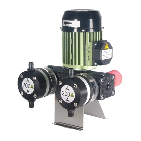
- Page 1 MULTIFERTIC...
- Page 2 INDEX 1.-GENERAL DESCRIPTION 2.-CARRIAGE AND MAINTENANCE 3.-TECHNICAL FEATURES 4.-OPERATION 5.- INSTALLATION Generalities Electric connection Hydraulic connection General installation scheme Additional module installation 6.- START UP 7.- MAINTENANCE Periodical maintenance List of parts List of parts additional module Problems: Causes and solution EC APPROVAL DECLARATION WARRANTY SAFETY RULES...
-
Page 3: General Description
(See materials in Technical Features). In case there is any doubt about compatibility of materials with the products to be used please contact with ITC S.L. Technical Service. Dosing flow of each module is adjustable independently with no need to stop... - Page 4 Codes formulation 60MF2 200 /3 C Cylinder made in PP and with ceramic piston CP Cylinder made in PVDF and with ceramic piston CI Cylinder made in INOX AISI 304 and with ceramic piston 230/400V 50/60HZ Three-phase 230V 50HZ Single-phase Maximum injection flow in l/h 60MF2 Series MULTIFERTIC two strokes per second...
-
Page 5: Technical Features
3.- TECHNICAL FEATURES There are two models of MULTIFERTIC MF injector MULTIFERTIC MF1: 1 injection per second MULTIFERTIC MF2: 2 injections per second MF 1 MF 2 MODULE FLOW PRESSURE MODULE FLOW PRESSURE l/h (GPH) BARS l/h (GPH) BARS MI1-25 MI2-50 50 (13) MI1-50... - Page 6 INJECTION MODULES DIMENSIONS WEIGHT 26.5 10.5 14.5 37.6 18.3 19.5...
-
Page 7: Operation
4.- OPERATION The electric motor (B) transmits its power by means of a reducer, made up of a pinion (E) and a ring gear (F) solidary to an axis (I) and an eccentric (A) that alternatively pushes and draws a shaft ( C) threaded to a piston (D). As a spring is not necessary for the return of the piston (POSITIVE RETURN), the motor transmits all its power both to the injection and to the suction, saving energy, avoiding breackdowns, and ensuring a perfect and high precision dosing. -
Page 8: Installation
5.- INSTALLATION GENERALITIES To install this pump it is advisable to choose places protected from water, away from heat sources and with renovation of air. Place the pump vertically over a totally horizontal rigid surface to achieve a proper lubrication of all inner elements. Anticipate which will be the room you will need to comfortably do the basic maintenance and install/desinstall the pump. -
Page 9: Single-Phase Connection
THREE-PHASE CONNECTION (50/60 Hz) To work at 230 V we will plug the motor in triangle. To work at 400 V it will be a star connection. 230 V 400 V OVERLOADED SWITCH 2.6 Amp 1.5 Amp SINGLE-PHASE CONNECTION To work at 230 V single-phase at 50 Hz we will connect directly the motor wire to the adequate protection. - Page 10 SUCTION It is essential to fit in the suction of the dosing liquid the filter of 100 mesh supplied with the dosing pump. Couple the suction pipe to the lower connecter of the cylinder, putting the mesh filter in between. The stuff at the bottom of the tank must never be suctioned, to avoid taking up undiluted particles.
-
Page 11: General Installation
GENERAL INSTALLATION 9 10 1. FILTER 2. VALVES 3. NON-RETURN VALVE 4. SUCTION 5. IMPULSION 6. SAFETY VALVE 7. SMALL DEPOSIT TO COLLECT LIQUID IN CASE OF BREAKOUT... - Page 12 INSTALLATION ADDITIONAL MODULE 62121 63125 63212 62121 EXTRACTOR 62401 62307 62142 ( 3rd and 4th module) 62141 (2nd module) MI2-50 MI1-25 MI2-100 MI1-50 MI2-200 MI1-100 MI2-300 MI1-150 MI2-500 MI1-250 MID2-50 MID1-25 MID2-100 MID1-50 MID2-200 MID1-100 MID2-300 MID1-150...
- Page 13 62401 63125 63212 63125 63124 (MI) 63332 (MID) 85308...
- Page 14 6.- START UP AND REGULATION STAND: Check that the pump is properly installed in its stand. OIL: Take off re-filling lid and fill the pump with the provided oil: SAE 80 W 90 or equivalent. If the pump has several modules oil must be spread to all filling holes.
- Page 15 PRIMING: To prime the pump easily, especially for not very important flows and we if do not have priming valve, we suggest to lower pressure up to the minimum injection point. If that is not possible, fill up the cylinder and the suction pipe with liquid..
-
Page 16: Periodical Maintenance
7.- MAINTENANCE Before any maintenance operation we will check: That the pump is stopped and disconnected from the electric supply. There is no pressure neither inside the head nor in the impulsion pipe. It is advisable to empty the head before opening it. The staff in charge of the maintenance will use the adequate protection means in order to manipulate the dosed liquid. - Page 17 MULTIFERTIC MF LIST OF PARTS 28002 28003 28004 28005 28009 MI1-25 MI1-50 MI1-100 MI1-150 63211 MI1-250 63214 MI2-50 63213 MI2-100 MI2-200 MI2-300 62100 63212 MI2-500 63115 62307 62402 62403 66165 62451 62162 62590 63603 50 y 100 L/H 200 y 300 L/H 66804 - P 66802 66803 - P...
- Page 18 63109 63510 63511 62506 63508 62507 62453 62500 62510 62451 63404 62400 63124 62131 62150 63212 63401 62401 63405 63503 66802 62141 64310 66804-P 63125 62142 66809-P 62119 62521 62310 63111 66333 62148 (M30) 62147 (M20) 62129 62132 62133 63420 62134 63421 62135...
- Page 19 MULTIFERTIC MF LIST OF PARTS CODE DESCRIPTION QUANTITY 63511 WASHER M5 DIN9021 A2 63213 WASHER 18x5x25 62453 RETAINING RING DIN 471 15 63405 WEDGING PIECE DIN 6885 5x5x10 63401 WEDGING PIECE 5x5x15 63420 COLLAR 50L *63421 COLLAR 100L *63422 COLLAR 200L *63423 COLLAR 300L *63424...
- Page 20 CODE DESCRIPTION QUANTITY *62123-I CYLINDER 300/L-S STAINLESS STEEL *62120-F CYLINDER 50/L-S PVDF *62121-F CYLINDER 100/L-S PVDF *62122-F CYLINDER 200/L-S PVDF *62123-F CYLINDER 300/L-S PVDF 62402 RING GEAR 2 STROKES, MULTIFERTIC , BRONZE 1 *62403 RING GEAR 1 STROKE, MULTIFERTIC, BRONZE 63404 ECCENTRIC 62500...
- Page 21 MODULE MI LIST OF PARTS 63109 63510 63511 62506 63508 62507 62453 62500 63405 62451 62510 62450 63124 62131 62150 63212 63404 62401 66802 62307 66804-P 66809-P 63503 62141 64310 63125 62142 62119 62521 63111 66333 62147 (M20) 62148 (M30) 62129 62132 62133...
- Page 22 LIST OF PARTS MI MODULE CODE DESCRIPTION QUANTITY 63511 WASHER M5 DIN9021 A2 62453 RETAINING RING DIN 471 15 63405 WEDGING PIECE DIN 6885 5x5x10 63420 SEAL 50L *63421 SEAL 100L *63422 SEAL 200L *63423 SEAL 300L *63424 SEAL 500L 62450 MOTOR MODULE AXIS 62131...
- Page 23 CODE DESCRIPTION QUANTITY 63404 ECCENTRIC 62500 REGULATOR ROD GUIDE 62150 MECHANIZED MODULE 62507 MULTIFERTIC REGULATOR 62119 CYLINDER SEPARATOR 63109 REGULATOR PLUG 3/8 62521 MULTIFERTIC REGULATOR BUMPER 62147 BELLOWS SHAFT M20 *62148 BELLOWS SHAFT M30 63111 BRAKE 62401 SUPPLEMENT 66801 SUCTION RETENTION VALVE P.P 66803-P SUCTION RETENTION VALVE O'RING P.P 66803-F...
-
Page 25: Ec Conformity Declaration
EC CONFORMITY DECLARATION I.T.C S.L.. Mar Adriàtic, 1 Polígono Torre del Rector 08130 Santa Perpètua de Mogoda Declares that all models of MULTIFERTIC products, identified by a serial number and year of manufacture, strictly fulfill 98/37/CE Governing Body, as long as installation, use and maintenance are carried out following the prevailing regulation and following the instructions contained in the handbook. - Page 26 Ed: 03/01/2005 - An C/ Del Mar Adriàtic nº 1 Pol. Ind. Torre del Rector P.O. Box 60 08130 STA. PERPETUA DE MOGODA BARCELONA - SPAIN Tel. 935 44 30 40 Fax 935 44 31 61 e-mail: itc@itc.es www.itc.es...
Need help?
Do you have a question about the TRIANGLE WATERQUIP MULTIFERTIC MF and is the answer not in the manual?
Questions and answers