Table of Contents
Advertisement
Quick Links
Advertisement
Table of Contents

Related Manuals for ITC DOSmart AC


Summary of Contents for ITC DOSmart AC
- Page 1 ENGLISH...
- Page 2 INDEX 1 GENERAL DESCRIPTION 2 PACKING AND STORAGE 3 TECHNICAL SPECIFICATIONS FLOW AND PRESSURE GRAPHS 4 INSTALLATION 4.1 GENERAL 4.2 ELECTRICAL CONNECTION 4.3 HYDRAULIC INSTALLATION 4.3.1 Installation examples 4.3.2 Installation recommendations 4.4 ACCESSORIES 4.4.1 Diaphragm leakage detector 4.4.2 Pressure sensor 4.4.3 Pulse output isolator 5 OPERATION 5.1 OPERATING MODES...
-
Page 3: Safety Instructions
5.3 ALARMS 5.3.1 Level alarm 1 5.3.2 Level alarm 2 5.3.3 Flow fault alarm 5.3.4 Diaphragm leakage alarm 5.3.5 Overpressure alarm 5.4 MONITOR 5.4.1 Real time 5.4.2 Counters 5.4.3 Info Unit 6 START-UP AND REGULATION 7 MAINTENANCE Exploded view Periodic Maintenance: Troubleshooting: Possible cause and solution Electrical Wiring CE DECLARATION OF CONFORMITY... -
Page 4: General Description
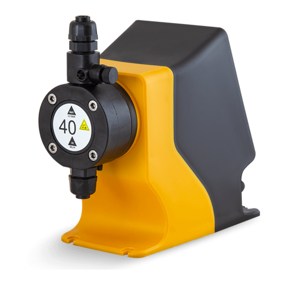
Product description 1 GENERAL DESCRIPTION DOSmart AC is a series of dosing pumps with a step motor and advanced control functions to automate This series of pumps is characterized by high precision, extensive regulation (1:3000) and high suction up to 16 bar. The choice of the correct head material between PP, PVDF and stainless steel allows the dosing of any commonly used chemical in the water treatment, chemical, food and agriculture industries. -
Page 5: Packing And Storage
The original packaging is designed to allow the equipment to be transported and stored without damage, provided this takes place in dry, ventilated spaces away from heat sources. The packing contains: - DOSmart AC dosing pump - Instruction manual - Connection accessories for 4x6, 6x8, 6x12, 10x12 conduit... -
Page 6: Technical Specifications
Product description 3 TECHNICAL SPECIFICATIONS 55-STA... / 55-STD ... S50-D50 F50-D50 F30-D50 F51-D50 F31-D50 F41-D69 F31-D69 Flow max. at P max. 0.40 1.05 2.10 3.40 6.60 10.50 15.80 Max. pressure Diaphragm diameter Stroke Cycles/min Volume/cycle at Pmax ml 0.63 0.82 0.93 2.36 2.54... - Page 7 Product description Inputs/outputs • Analogue input 0/4-20 mA • RS-485 ModBus serial port • External pulse input • 4-20 mA logging and monitoring output • Remote activation input (on/off) • Log output, monitoring and control of second • Level sensor input (pre-warning) pulse pump •...
- Page 8 S50-D50 FLOW AND PRESSURE GRAPHS Pressure compensation activated Pressure compensation deactivated 14 - F50-D50 F30-D50 13 - 12 - 11 - 10 - 29 - 18 - F31-D50 F51-D50 28 - 27 - 16 - 26 - 14 - 25 - 24 - 12 - 23 -...
-
Page 9: Installation
Installation 4 INSTALLATION 4.1 GENERAL It should be installed in a place protected from water, away from heat sources and with renovation of air. Fix the pump on a rigid horizontal surface. Provide enough space to comfortably perform basic maintenance and facilitate installation and removal. Fix the pump to the chosen flat surface using 4 screws (See drawing). -
Page 10: Electrical Connection
+2 4 +5 V H 4-20 mA PULSE REMOTE LEVEL 1 LEVEL 2 4-20 mA PULSE ALM LEVEL REMOTE REMOTE LEVEL 1 LEVEL 2 4-20 mA Pulse input Remote activation COMMON ITC controllers ITC flowmeter Level sensors External quick connectors... - Page 11 Installation WIRING FUNCTION DETAIL Inputs Encoder +12 Vdc Encoder Encoder Encoder Encoder Flow detector Flow detector Leak detector Leak detector Pressure transmitter +24 Vdc Pressure transmitter Pressure transmitter 4-20 mA input analogue mode 4-20 mA input analogue mode Proportional pulse input mode Pulses Proportional pulse input mode Remote...
-
Page 12: Hydraulic Installation
Installation 4.3 HYDRAULIC INSTALLATION 4.3.1 Installation examples 10 11 1. To avoid undissolved particles, never suck the product to be injected from the bottom of the tank. 2. Filter. It is essential to install a filter (150 micron) in the suction piping. 3. -
Page 13: Installation Recommendations
Installation 4.3.2 Installation recommendations SUCTION Long suction: L> 2 m (6.5 ft) PIPE SIZE Øint L ≤ 2 m L ≤ 5 m Q max. (l/h) Q max. (l/h) Ø Air in suction DISCHARGE Long discharge: L> 5 m (16 ft) Ø... - Page 14 The pulse output isolator allows any device to be securely connected to a pulse output. The pulse output is a voltage free output. The isolator is not necessary when the output is connected to a 38 39 40 41 pulse input of another DOSmart AC.
-
Page 15: Operation
Installation 5 OPERATION The electric motor transmits power via a reducer, consisting of a pinion (A) and an eccentric crown (B) that drives a connecting cam (C) onto which the diaphragm (D) is screwed. Spring (F) is compressed during the suction cycle, thus storing energy which is released during the discharge cycle. By varying the speed of the motor and depending on the operating mode selected in the Control Unit, the equipment will regulate the flow to the desired value with a maximum variation of 1:3000. -
Page 16: Lcd Display Description
Installation LCD DISPLAY DESCRIPTION Advanced dosing function Programming locked 1 0 0 % flow 25.0 Level 1 Level 2 1 4 4 Cycles/min l / h Flow rate fault Leakage MODE ON/OFF Overpressure Loss of pulse Mode Setup Alarm Monitor Menus 5.1 Operating mode menu 5.2 Configuration menu... -
Page 17: Operating Modes
Installation 5.1 OPERATING MODES 5.1.1 Manual mode This mode allows manual adjustment of the dosing flow rate. 0 0 0 0 0 0 25.0 25.0 Manual MODE: Proportional 0 0 0 Analog 0 0 0 l / h l / h Batch MODE Increase/decrease flow... - Page 18 Installation PROPORTIONAL X:Y Select the number of pump cycles Change by pressing and validate by pressing 0001 0001 Q = 025 % M = 005 pulses PROPORTIONAL X:Y Select pump speed in % Change by pressing and validate by pressing 0001 0001 For Y=1 Q must be set at less than 50%...
- Page 19 Installation Select ON to perform proportional dosing with a volume limit. PROPORT. The pump will stop when it reaches the ENT maximum volume Set Point 000,05 to be dosed. Stop Pump Change by pressing and validate by pressing Stop Vol (1) 03,6 Set the desired maximum volume.
- Page 20 Installation ANALOG INPUT Select mA output for the second point INPUT Change by pressing and validate by pressing 16,0 mA 100 % ANALOG INPUT Select the flow rate in % for the second point in mA SPAN 4 mA 000 % Change by pressing and validate by pressing 20 mA...
- Page 21 Installation Batch dosing mode settings 5.1.4.1 Select start-up mode BATCH MODE Start Man. Manual: start the pump by pressing Flow 000 % Stop Stroke BATCH MODE Start Ext .: start pump via remote input Flow 000 % Stop Stroke BATCH MODE Time: start the pump using a timer by entering a frequency Start Time...
- Page 22 Installation BATCH MODE Time: set runtime before stop Start Man. Flow 050 % Stop Time BATCH MODE Start Man. Flow 050 % Change by pressing and validate by pressing Stop 00 : 00 : 10 Volume 34,722 ml Configuration modes view Volume to be dosed 01,379 l Start :...
- Page 23 Installation 5.1.5 ModBus mode The pump can be controlled via the RS485 serial port and a ModBus RTU protocol. See the complete ModBus manual. - Bus: RS485 - Communication: half-duplex L(H), H(B), and GND - Baud rate: 9600 - Data bits: 8 - Parity: None - Stop bits: 1 - Hardware handshake: No...
- Page 24 Installation 5.2 CONFIGURATION 5.2.1 Pump calibration The pump calibration function allows the pump flow to be calibrated in real working conditions via a product suction test of a given duration. For a correct calibration, a test duration of at least 60 seconds must be entered.
- Page 25 Installation 5.2.2.1 Low pulsation standard The Standard ST mode is the normal operating mode where the doser has symmetrical behaviour during suction and discharge of the product while working at maximum capacity. As the flow rate is reduced, the discharge cycle is extended, keeping the suction duration constant. 100% operation 50% operation DOSING MODE...
- Page 26 Installation 5.2.3 Setup 5.2.3.1 Dosing pump Technical characteristics of the pump 0 0 0 SET UP 25.0 CONFIGURATION DOSING PUMP 0 0 0 PUMP CALIBRATION UNITS l / h DOSING MODE FLOWMETER SET UP LOCK CODE IN / OUT MODE MODBUS Pump flow rate Real Flow is the flow rate resulting from the calibration, if it has been performed.
- Page 27 Installation Auto: If the pump has a pressure sensor connected, by selecting this option the pump will keep the flow unchanged even if the working pressure changes. Manual (MAN): If the pump does not have a pressure sensor, but the working pressure is constant, the pressure value can be entered manually so that the pump adjusts to the nominal flow value.
- Page 28 Installation 5.2.3.3 Flowmeter For a correct water flow reading, the flowmeter constant (volume/pulse or pulses/volume) must be entered. Previously select the type of flowmeter for low or high frequency. Low frequency: for water meters with low frequency outputs (0.005 Hz to 30 Hz). The constant is expressed in volume/pulse (litres/pulse;...
- Page 29 Installation 0 0 0 25.0 0 0 0 l / h Pressing for 3 seconds locks the pump MODE CODE **** Press for 3 seconds to enter the code and unlock the pump 0000 Enter the code starting with the units (from right to left). CODE **** Change values by pressing and validate by...
- Page 30 Installation 5.2.4 Inputs/outputs 5.2.4.1 Pressure input Calibration of the 4-20 mA pressure transducer input. 0 0 0 25.0 CONFIGURATION INPUTS PRESSURE PUMP CALIBRATION FLOW DETECTOR 0 0 0 DOSING MODE l / h OUTPUTS SET UP PULSES IN / OUT 4-20mA MODE PRESSURE INPUT...
- Page 31 Installation Enter the volume of product PULSE OUTPUT PULSE OUTPUT dispensed for each product. Out = Dosed Vol Out = Dosed Vol Change by pressing validate by pressing 1/pulse 1/pulse With this option another device can receive the dosed volume. Review 5.5.4 for connections. 5.2.4.4 4-20 mA output 4-20 mA output for logging or monitoring.
- Page 32 Installation 5.3 ALARMS In the event of an alarm, the corresponding icon will flash on the main screen. If the cause of the alarm disappears the icon will remain steady. To erase the alarm icon, it is necessary to stop and start the pump using the “ENT”...
- Page 33 Installation LEVEL 2 EMPTY Activate or deactivate the alarm by pressing and validate Alarm Level 2 relay by pressing Stop pump LEVEL 2 EMPTY LEVEL 1 PRE EMPTY Activate or deactivate the Alarm Relay output, when the unit is in Alarm Alarm alarm, by pressing...
- Page 34 Installation 5.3.4 Diaphragm leakage alarm Diaphragm rupture detection alarm for electrically conductive liquids (min. 0.05 mS). MENU ALARM 25.0 LEVEL 1 0 0 0 LEVEL 2 l / h FLOW LEAKAGE MODE PRESSURE DIAPHRAGM LEAKAGE Activate or deactivate the alarm by pressing and validate Alarm Relay out...
- Page 35 Installation OVER PRESSURE LEVEL 1 PRE EMPTY Activate or deactivate, stop the pump when the alarm goes off, by Alarm Alarm pressing and validate by pressing Level relay Relay out Stop pump Stop pump 5.4 MONITOR 5.4.1 Real time Real-time working parameters 0 0 0 MONITOR 25.0...
- Page 36 Installation Total cycles COUNTERS Cycles since last reset Tot. St. 27136 Part. St. Volume since last reset 2971 Part. Vol.2 Total(h) Total operating time (hours) Short circuit alarms COUNTERS Overload alarms Sh. circ. High temperature alarms Over load Over temp High temperature alarms (chip) Th.
- Page 37 Installation 6 START-UP AND REGULATION FIXING: Check that the pump is properly secured HYDRAULIC CIRCUIT CHECK: Check that all valves are open, and that the priming and relief valve outlets are diverting the liquid to a container PUMP CHECK: Make a visual/auditory check of the correct operation of the pump. PRIMING: To facilitate pump priming, open the priming valve.
-
Page 38: Maintenance
Maintenance 7 MAINTENANCE EXPLODED VIEW 55-801-P 67104.2-P (D69) 55118-P (D50) 59300 55309 44303 55310 55120 55-835-P 63333 55200 (D50) 67105.2-P (D69) 55111-P (D50) 55110-P 55-800-P 55-100 55119 55103 55-109 55116 55-109 55105 55303 55302 55306 55305 55304 55154 55601 Piñón 63213 MODEL CROWN PINION... - Page 39 Maintenance 55202 55150 55309 29620 55149 55-100 59309 55606 55605 59353 55655-M12 73654-M2 73615-M12 C...
-
Page 40: Parts List
Maintenance PARTS LIST CODE DESCRIPTION QUANTITY 29620 ACU inverter connection PCB 44303 7.5 x 2.5 FPM O-ring 55-100 Dosmart-6 mechanism 55103 Dosmart shaft 55105 Dosmart spring 55106 Pinion red3_19 55107 Red3-57 eccentric crown 2.25 55-109 Dosmart cam 55110-P Diaphragm cylinder D50 55111-P D50 diaphragm base 55116... - Page 41 Maintenance 6X12 VALVES (60 l/h max.) Discharge Suction 55-801-P 55-800-P 62310 60813.1-P 64348 60811.1-P 60308 55822-P Flanges 62310 60813.1-P Pins 64348 60308 62310 55822-P 62310 55819-P 55820-P 62310 62310 60813.1-P Pins 64348 Flanges 60308 60812.1-P 60811.1-P 62310 Pipes 6x12 10x12 Flanges 55826-P 60878.1-P...
-
Page 42: Periodic Maintenance
Maintenance Before any maintenance operation check: The pump is stopped and disconnected from the power supply . There is no pressure inside the head or in the discharge pipe. It is recommended to empty the head before opening it. Maintenance personnel should use the appropriate means of protection for handling the liquid being dosed. - Page 43 - Bad contact in power connector - Check the electronics power connectors AL-1 - Internal short circuit - Contact ITC technical service - Blocking of the pump due to - Check for any closed valve in the pump overpressure or mechanism fault...
- Page 44 Maintenance PROBLEM CAUSE SOLUTION Motor runs but pump - Pump not primed - Prime the pump by opening the priming does not inject or valve or filling the head with the liquid to dosing is lower than be injected nominal - Dirty or damaged suction or - Clean or change valves discharge valve...
-
Page 45: Electrical Wiring
4-20 mA PULSE REMOTE LEVEL 1 LEVEL 2 4-20 mA PULSE ALM LEVEL 1 REMOTE 2 REMOTE 3 LEVEL 1 4 LEVEL 2 4-20 mA Pulse input Remote activation 5 COMMON ITC controllers ITC flowmeter Level sensors External quick connectors... -
Page 47: Ce Declaration Of Conformity
Polígono Industrial Can Bernades-Subirà 08130 Santa Perpètua de Mogoda Declares that all models of DOSmart AC products identified with serial number and year of manufacture comply with Machinery Directive 2006/42/EC, Low Voltage Directive D2014/35/ EU and Electromagnetic Compatibility Directive D2014/30/EU, provided that the installation, use and maintenance are carried out in accordance with current regulations and following the instructions in the instruction manual. - Page 48 Original Manual Ed: 17/02/2021-EN C/ Vallès, 26 Pol. Ind. Can Bernades - Subirà P.O. Box 60 08130 Santa Perpètua de Mogoda BARCELONA Tel. 93 544 30 40 Fax 93 544 31 61 e-mail: itc@itc.es www.itc-dosing-pumps.com...
Need help?
Do you have a question about the DOSmart AC and is the answer not in the manual?
Questions and answers