Table of Contents
Advertisement
Quick Links
Advertisement
Table of Contents

Related Manuals for ITC Dostec AC


Summary of Contents for ITC Dostec AC
- Page 1 DOSTEC AC ENGLISH...
- Page 2 INDEX 1. GENERAL DESCRIPTION 2. PACKING AND STORAGE 3. TECHNICAL SPECIFICATIONS 4. OPERATION 4.1 OPERATING MODES 4.1.1. Manual mode 4.1.2. Proportional mode 4.1.3. Analogue mode 4.1.4. Batch mode 4.1.5 ModBus mode 4.2 CONFIGURATION 4.2.1 Pump calibration 4.2.2 Dosing mode 4.2.3 Configuration 4.2.4.
-
Page 3: Warranty
5.4.1. Installation examples 5.4.2. Installation recommendations 5.5. ACCESSORIES 5.5.1. Diaphragm leakage detector 5.5.2. Flow detector 5.5.3. Pressure sensor 5.5.4. Pulse output isolator 5.5.5. Additional ventilation 115 / 230 V 6. START-UP AND REGULATION 7. MAINTENANCE 7.1. EXPLODED VIEW AC3 PISTON 7.2. -
Page 4: General Description
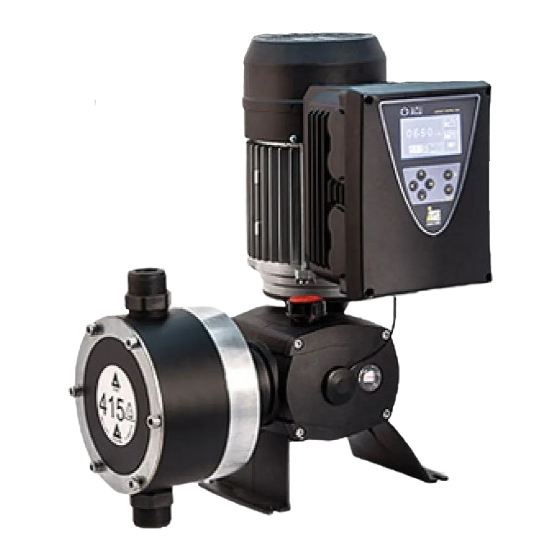
Descripción de producto 1. GENERAL DESCRIPTION Dostec AC is a diaphragm or piston dosing pump with advanced control for an accurate and efficient automatic dosing. This series allows many dosing possibilities depending on the chosen head. The flow range covers needs from 3 to 1200 l/h at a pressure of up to 20 bar. -
Page 5: Packing And Storage
Descripción de producto Code formulation MOTOR HEAD FREQUENCY STROKE AC1: 0.43 kW 110 V P: Piston 1: 26 Strokes/min 1: 4.5 mm AC2: 0.43 kW 230 V D: Diaphragm 2: 43 Strokes/min 2: 7.5 mm AC3: 1.2 kW 230 V 3: 72 Strokes/min 3: 9 mm 4:144 Strokes/min... -
Page 6: Technical Specifications
Descripción de producto 3. TECHNICAL SPECIFICATIONS SS (Slow Suction) *Suction Max. *Max. FLOW PRESSURE FLOW lift viscosity viscosity CODE mPas mPas 73-AC3P44-P110_X 1200 317 500 (E) 73-AC3P44-P95_X 1500 (E) 73-AC3P44-P77_X 2000 (E) 73-AC2 73-AC1 P44-P77_M 800 (C) 73-AC3P43 -P77_X 2000 (E) 73-AC2 73-AC1 P44-P61 _M 1500 (B) - Page 7 Descripción de producto VOLTAGE: AC3: 230V ±10% AC2: 110V ±10% POWER: 0.43 kW (0.58 Hp) 1.2 kW (1.6 Hp) PROTECTION: IP-55 MATERIALS: Piston: P.E.U.A.P.M. / Ceramic / AISI316 Diaphragm: P.T.F.E. Fibre-reinforced elastomer base Retention: Cylinder: P.P. / PVDF / AISI316 Valve (body): P.P.
- Page 8 Configuración Inputs/outputs • Analogue input 0/4 - 20 mA • RS-485 ModBus serial port • External pulse input • 4 - 20 mA log and monitoring output • Remote activation input (on/off) • Log output, monitoring and control of second •...
- Page 9 Configuración 73-AC_D43-D115 73-AC_D42-D95 175- 340- 165- 320- 155- 300- 145- Bars Bars 73-AC_D43-D95 73-AC_D42-D115 290- 200- 52,5- 190- 270- 47,5- 180- 250- 170- Bars Bars 73-AC_D43-D115 340- 320- 300- Bars DIAPHRAGM PUMP AC3 73-AC3D33-D142 73-AC3D42-D142 480- 84.5- 320- 130- 460- 80.5- 305- 130-...
-
Page 10: Operation
Configuración 220- 73-AC3D43-D163 73-AC3D44-D163 1240- 820 - 320- 210- 1200- 780 - 310- 200- 1160- 740 - 190- 300- 700 - 1120- 180- 290- 660 - 1080- 170- 280- 620 - 1040- Bars 270- Bars 72 PSI 4. OPERATION The rotational motion of the motor is transmitted by the reducer, which consists of two major components, the pinion (A) and the ring gear (B). -
Page 11: Lcd Screen Description
Configuración LCD SCREEN DESCRIPTION Advanced Dosing Function Program blocked 1 0 0 % Flow 0240 Level 1 Level 2 1 4 4 Strokes/min l / h Flow failure Leakage ON / OFF MODE Overpressure Pulse loss Mode Configuration Alarm Monitor Menus 4.1 Operating Modes 4.2 Configuration... -
Page 12: Operating Modes
Configuración 4.1 OPERATING MODES 4.1.1. Manual mode This mode allows manual adjustment of the dosing flow rate. 0 0 0 0 0 0 0240 0240 Manual MODE: Proportional 0 0 0 Analog 0 0 0 l / h l / h Batch ModBus MODE... - Page 13 Configuración PROPORTIONAL X:Y Select the number of pump cycles Change values by pressing and confirm by 0001 0001 pressing Q = 025 % M = 005 pulses PROPORTIONAL X:Y Select pump speed in % Change by pressing and confirm by pressing 0001 0001 For Y = 1 Q must be set at less than 50%...
- Page 14 Configuración Select ON to perform proportional dosing with a volume limit. PROPORT. The pump will stop when it reaches the ENT maximum volume Set Point 000,05 to be dosed. Stop Pump Change by pressing and confirm by pressing Stop Vol (1) 03,6 PROPORT.
- Page 15 Configuración ANALOG INPUT INPUT Select mA output for the second point Change by pressing and confirm by pressing 16,0 mA 100 % ANALOG INPUT SPAN Select the flow rate in % for the second point in mA 4 mA 000 % Change by pressing and confirm by pressing 20 mA...
- Page 16 Configuración Batch dosing mode settings 4.1.4.1 Select start-up mode BATCH MODE Start Man. Manual: start the pump by pressing Flow 000 % Stop Stroke BATCH MODE Start Ext.: start the pump via remote input Flow 000 % Stop Stroke BATCH MODE Start Time Time: start the pump via a timer by entering a frequency...
- Page 17 Configuración BATCH MODE Start Man. Time: set cycle execution time before stopping Flow 050 % Stop Time BATCH MODE Start Man. Change by pressing and confirm by pressing Flow 050 % Stop 00 : 00 : 10 Volume 333,33 l Viewing the different configuration modes Volume to be dosed 01,379 l...
- Page 18 Configuración 4.1.5 ModBus mode This operation mode allows the control of the pump through the serial port RS485 and Modbus RTU protocol. 0 0 0 0 0 0 0 240 0240 MODE: Manual Proportional 0 0 0 0 0 0 Analog l / h l / h...
- Page 19 Configuración 4.1.5.1 Remote activation An external remote control can be used to start and stop the pump by means of dry contact in pins 17-18. 4-20mA REMOTEL EVEL 1 LEVEL 2 PULSE STOP 17 18 RUN (factory default) 17 18 When the contact is closed (RUN) the pump may be run manually via the ENT key.
- Page 20 Configuración PUMP CALIBRATION TEST TIME Change by pressing and confirm by pressing ENT to start PUMP CALIBRATION PUMP CALIBRATION Enter the value in the unit PROGRESS Dosed volume 03,333 confirm by pressing Strokes Speed P. 0415 Max.Curr. 04,5 Press to finish the calibration process PUMP CALIBRATION Dvol: volume dosed DVol...
- Page 21 Configuración 4.2.2.2 Low flow The Low Flow mode (LF) allows dosing to be paused during the discharge cycle, extending the dosing time and therefore reducing the flow to as little as 1%. The other modes allow the flow to be reduced to as little as 10%. DOSING MODE Mode: Low Flow...
- Page 22 Configuración 4.2.3 Configuration 4.2.3.1 Dosing pump Technical characteristics of the pump 0 0 0 SET UP 0240 CONFIGURATION DOSING PUMP PUMP CALIBRATION 0 0 0 UNITS l / h DOSING MODE FLOWMETER SET UP LOCK CODE IN / OUT MODE MODBUS Pump flow rate Real Flow is the flow due to the calibration test, if carried out, and/or the flow due to the regulator.
- Page 23 Configuración 4.2.3.2 Units Select flow, pressure and proportionality units 0 0 0 SET UP 0240 CONFIGURATION DOSING PUMP PUMP CALIBRATION 0 0 0 UNITS l / h DOSING MODE FLOWMETER SET UP LOCK CODE IN / OUT MODE MODBUS UNITS Change litre/gallons by pressing and confirm by Flow...
- Page 24 Configuración Change by FLOWMETER FLOWMETER FREQUENCY : pressing and confirm FREQUENCY : HIGH 010.77 / puls 010.77 puls / by pressing TIME Q=0 : TIME Q = 0, Time interval (seconds) between two pulses to consider zero flow. 4.2.3.4 Lock code Blocks access to the equipment configuration, allowing the pump to start and stop.
- Page 25 Configuración MODBUS ADDRESS Address: Baudrate: 9600 Change by pressing and confirm by pressing Data Bits: Parity: Stop Bits: MODBUS ADDRESS Address: Baudrate: 9600 Change by pressing and confirm by pressing Data Bits: Parity: Stop Bits: MODBUS ADDRESS Address: Baudrate: 9600 Change by pressing and confirm by pressing Data Bits:...
- Page 26 4-20mA MODE Set if the pulse output is the same as the pulse input. PULSE OUTPUT With this option a second Dostec AC can be driven by the same Out = Pulse In flowmeter in proportional (%) mode. Enter the volume of product...
- Page 27 Configuración 4.3 ALARMS In the event of an alarm, the corresponding icon will flash on the main screen. If the cause of the alarm disappears the icon will remain steady. To erase the alarm icon, it is necessary to stop and start the pump using the “ENT”...
- Page 28 Configuración LEVEL 2 EMPTY LEVEL 1 PRE EMPTY Activate or deactivate the Alarm Relay output, when the unit is in Alarm Alarm Level relay Level 2 relay alarm, by pressing and confirm by pressing Stop pump Stop pump LEVEL 2 EMPTY LEVEL 1 PRE EMPTY Activate or deactivate, stop the pump when the alarm goes off, by Alarm...
- Page 29 Configuración DIAPHRAGM LEAKAGE LEVEL 1 PRE EMPTY Activate or deactivate the Alarm Relay output, when the unit is in Alarm Alarm Level relay Relay out alarm, by pressing and confirm by pressing Stop pump Stop pump DIAPHRAGM LEAKAGE Activate or deactivate, stop the pump when the alarm goes off, by Alarm pressing and confirm by pressing...
- Page 30 Configuración Analogue input value (mA) External pulse input value (Hz) INPUTS Pressure sensor input value (bar/psi) 0/4-20mA Pulse Hz External pulse input value (ON-OFF) Press Bar Pulse x:y Remote control input Remote St/min Pulse Flow Number of strokes per minute Flow sensing value OUTPUTS Analogue output (mA)
-
Page 31: Instalación
Instalación 5. INSTALLATION 5.1. GENERAL It should be installed in a place protected from water, away from heat sources and with renovation of air. Place the pump vertically over a totally rigid surface to achieve a proper lubrication of all inner elements. Provide sufficient space to facilitate basic maintenance and installation/removal of the pump. - Page 32 VENTILACIÓN RS-485 12VF MN+M N- +2 4 +5 V H 4 - 20 mA PULSO REMOTO NIVEL 1 NIVEL 2 4 - 20 mA PULSO ALM NIVEL 4 - 20 mA Pulse input ITC controllers ITC Flowmeter External quick connectors...
- Page 33 WIRING Instalación FUNCTION DETAIL Inputs Encoder +12 V dc Encoder Encoder Encoder Flow detector (−) Flow detector Leakage detector (−) Leakage detector Leakage detector (−) Pressure transmitter +24 V dc Pressure transmitter Pressure transmitter (−) Analogue mode input 4 - 20 mA Analogue mode input 4 - 20 mA (−) Proportional mode pulse input...
-
Page 34: Hydraulic Installation
Instalación 5.4. HYDRAULIC INSTALLATION 5.4.1. Installation examples 10 11 1. To avoid undissolved particles, never suck the product to be injected from the bottom of the tank. 2. Filter. It is essential to install a filter (150 micron) in the suction piping. 3. - Page 35 Instalación 5.4.2. Installation recommendations SUCTION Long suction: L> 2 m (6.5 ft) RECOMENDED PIPE SIZE Øint L ≤ 2 m L ≤ 5 m AC1/ 2 1000 Ø 1000 Q max. (l/h) Air in suction DISCHARGE Long discharge: L> 5 m (16 ft) RECOMENDED PIPE SIZE Øint L ≤...
- Page 36 Instalación 5.5. ACCESSORIES 5.5.1. Diaphragm leakage detector The diaphragm leakage detector is an electrical conductivity sensor capable of detecting the presence of liquid when its conductivity is 0.05 mS or higher. The pump must be provided with the specific diaphragm flange for housing the detector.
- Page 37 The pulse output is a voltage free output. The pulse output isolator is not necessary when this output connects with a pulse input of another Dostec AC. 5.5.5. Additional ventilation 115 / 230 V The installation of this accessory is necessary in those cases in which the pump is operated continuously at temperatures above 40 ºC (104 °...
- Page 38 Mantenimiento 27-051 7. MAINTENANCE 7.1. EXPLODED VIEW AC3 PISTON 28054 29321 66344 (x4) 62352 (x4) 71304 71107(144c/min) 71137(72c/min) 62451 71309 (x4) 71308 61337 71151 71306 71-031 62129 64310 71124 61336 61-011-F 64412 61-855-P 62166(x4) 71314 61-131-/C (P110) 61-134-/C (P95) 61-136-/C (P77) 71123 61137 (P110)
- Page 39 Mantenimiento 60301 66334 66344 60109 60315 60333 71-030 (c15-7,5) 71111(c15-7,7) 71-029 (c10-5) 71112(c10-5) 60314 60110(c15-7,7) 71127(c10-5) 29-036 29-035 71184(15mm) 71187(10mm) 71188(7,5mm) 71106(144c/min) 71189(5mm) 71136(72c/min) 71310 71310 71307 71303 71311 71185.1 60156 71313(x4) 71186 62166(x4) 60300 60304(x3) 29-059.1 29-057.1 65466 61-885-P 61-875-P 61-011-F/I 61-010-F/I...
-
Page 40: Mantenimiento
Mantenimiento LIST OF PARTS AC3 (Piston) CODE DESCRIPTION UNITS 28054 Electric motor 1.2 kW 6P 110/190 3 ph 80/100 B14 29321 Seal motor T80 Maraz 29620 Control board AC 29622 Power board 230 V ac 33429 Screw M4 x 20 DIN 912 a-2 38301 Screw M3 x 8 DIN 7985 A2 60109... - Page 41 Additional ventilation 24 V D50/ EF low presure 29-035 Control PCB with cover DOSTEC AC 29-037 Power PCB with box AC2 29-057.1 PCB, base and cover encoder DOSTEC AC 29-059.1 Encoder with cover AC3 (Dostec-50) 71-029 Regulator p 1 mm D50 assembly 71-030 Regulator p 1.5 mm D50 assembly...
- Page 42 Mantenimiento 27-051 7.2. EXPLODED VIEW AC3 DIAPHRAGM 28054 29321 66344 (x4) 62352 (x4) 71304 71107(144c/min) 71137(72c/min) 62451 71309 (x4) 71308 61337 71151 71306 71-032 62166(x4) 62129 64310 61-011-F 61336 63331(x4) 61-855-P 71217 (D142) 71218 (D163) 71221 (D142) 71222 (D163) 71226 (D142) 71225 (D163) 71214.1...
- Page 43 Mantenimiento 60301 66334 66344 60109 60315 60333 71-030 (c15-7,5) 71111(c15-7,7) 71-029 (c10-5) 71112(c10-5) 60314 60110(c15-7,7) 29-036 71127(c10-5) 29-035 71184(15mm) 71187(10mm) 71106(144c/min) 71188(7,5mm) 71136(72c/min) 71189(5mm) 71310 71310 71307 71303 71185.1 71311 60156 71313(x4) 71186 62166(x4) 60300 60304(x3) 29-059.1 29-057.1 65466 61-885-P 61-875-P 61-011-F/I 61-010-F/I...
- Page 44 Mantenimiento LIST OF PARTS AC3 (Diaphragm) CODE DESCRIPTION UNITS 28054 Electric motor 1.2 kW 6P 110/190 3 ph 80/100 B14 29321 Seal motor T80 Maraz 60109 Regulator knob Dostec 60110 Regulator guide p1.5 mm Dostec 60156 Magnet for encoder d6 x 2.5 60300 Oil peep hole 60301...
- Page 45 Additional ventilation 24 V D50/ EF low presure 29-035 Control PCB with cover DOSTEC AC 29-037 Power PCB with box AC2 29-057.1 PCB, base and cover encoder DOSTEC AC 29-059.1 Encoder with cover AC3 (Dostec-50) 71-029 Regulator p 1 mm D50 assembly 71-030 Regulator p 1.5 mm D50 assembly...
- Page 46 Mantenimiento 27-050 7.3. EXPLODED VIEW AC 1/2 PISTON 28053 29319 62352(x4) 60116 (144c/min) 60117 (72c/min) 60137 (43c/min) 60138 (26c/min) 63213 63212 60111 60319 60320(x5) 60312 63124 60151 60302(x4) P.E. / Ceramic 60-014 64412 62-132 / 62-143 (D24) 60-023(500L) 62-133 / 62-144 (D34) 60-125 / 62-145 (D49) 60-126 / 62-146 (D61) 60-127 (D77)
- Page 47 Mantenimiento 60301 66334 66344 60109 60318 60315 60333 60-022 (p1,5) 60-021 (p0,9) 60108(p1,5) 60209(p0,9) 60314 29-036 60110(p1,5) 29-035 60112(p0,9) 60305 60115 (144c/min) 60114 (72c/min) 60133 (43c/min) 62453 60134 (26c/min) 61305 62453 60154.1 60156 60158 63212(x4) 62451 60300 60304(x3) 60157(15mm) 60159(10mm) 61324 60160(7,5mm) 62451...
- Page 48 Mantenimiento LIST OF PARTS AC1/2 (Piston) CODE DESCRIPTION UNITS 28053 Motor 230 kW AC1/2 29118 Motor adapter for inverter 0.5 Hp 110 V 29319 Seal motor Marax T71 60108 Regulator rod 15 Dostec 60109 Regulator knob Dostec 60110 Regulator guide p1.5 mm Dostec 60111 Pinion bumper Dostec 60112...
- Page 49 Additional ventilation 24 V dc IP56 DOSTEC AC1-2 29-035 Control PCB with cover DOSTEC AC 29-036 Power PCB with box AC1/3 29-057.1 PCB, base and cover encoder DOSTEC AC 29-058.1 Encoder with cover AC1-2 (Dostec-40) 60-014 Rod slider D40-P assembly 60-021 Regulator p 0.9 mm D40 assembly...
- Page 50 Mantenimiento 27-050 27-051 7.4. EXPLODED VIEW AC 1/2 DIAPHRAGM 28054 29307 (x4) 29118 29318 62352(x4) 60116 (144c/min) 60117 (72c/min) 60137 (43c/min) 60138 (26c/min) 63212 63213 60111 60320(x5 60319 63124 60312 60151 60302(x4) 60313 60-015 67104.2-P/F (D69) 67104-I (D69) 62129 62-859-P (6x12) 62-857-P (3/4) 64310 63125...
- Page 51 Mantenimiento 60301 66334 66344 60109 60318 60315 60333 60-022 (p1,5) 60-021 (p0,9) 60108(p1,5) 60209(p0,9) 60314 29-036 29-035 60110(p1,5) 60112(p0,9) 60305 60115 (144c/min) 60114 (72c/min) 60133 (43c/min) 62453 60134 (26c/min) 61305 62453 60154.1 60156 60158 63212(x4) 62451 60300 60304(x3) 60157(15mm) 60159(10mm) 61324 60160(7,5mm) 62451...
- Page 52 29118 Motor adapter for inverter 0.5 Hp 110 V 29129 Advanced Control case 29131 Advanced Control lid 29132 Case seal DOSTEC AC 29202 Lexan Dostec AC 29307 Screw M4 x 15 DIN 7991 29312 O-ring 32 x 2 FPM 29315...
- Page 53 70304 Screw M5 x 20 DIN 912 I ASSEMBLIES 27-050 Additional ventilation 24 V dc IP56 DOSTEC AC1-2 29-057 PCB and base encoder DOSTEC AC 29-058 Encoder AC1-2 (Dostec-40) 60-015 Rod slider D40-D assembly 60-021 Regulator p 0.9 mm D40 assembly 60-022 Regulator p 1.5 mm D40 assembly...
- Page 54 Mantenimiento VALVES 60-808.1-F/I Suction check valve hose 6 x 12-¾ 60-809.1-F/I Discharge check valve hose 6 x 12-¾ 60-858-P Suction check valve 6 x 12-¾" PP Borosilicate 60-859-P Discharge check valve 6 x 12-¾" PP Borosilicate 62-806-F Suction check valve ¾" PVDF 62-807-F Discharge check valve ¾"...
-
Page 55: Priming Valves
Mantenimiento 6 x 12 VALVES (60 l/h max.) PP/PVDF AISI 316 Discharge Suction Discharge Suction 60-859-P 60-858-P 60-809.1-I 60-808.1-I 60-809.1-F 60-808.1- F 62310 60811.1-I 62310 60811.1-P/F 60813.1-I 60813.1-P/F 60877 64351 64348 (Boro) 60877 60308 60812.1-I 60308 62310 60812.1-P/F 60810.1-I 60810.1-P/F 62310 60810.1-I 60810.1-P/F... -
Page 56: Periodic Maintenance
Mantenimiento Before any maintenance operation check: The pump is stopped and disconnected from the power supply. There is no pressure inside the head or in the discharge pipe. It is recommended to empty the head before opening it. Maintenance personnel should use the appropriate means of protection for handling the liquid being dosed. - Page 57 – Input voltage too high – Check the input voltage with a voltmeter – Internal short circuit – Contact ITC technical service – Motor phase failure – Check the wiring between the motor and the electronic card. – High temperature. Additional –...
- Page 58 PULSE ALM LEVEL 4 - 20 mA PULSE REMOTE LEVEL 1 LEVEL 2 Black Violet Yellow Blue White 230V Encoder Violet 12v F1 F2 S - Black Yellow White 4 - 20 mA Pulse input Blue ITC controller ITC flowmeter...
-
Page 59: Ce Declaration Of Conformity
Polígono Industrial Can Bernades-Subirà 08130 Santa Perpètua de Mogoda Declares that all models of DOSTEC AC products identified with serial number and year of manufacture comply with Machinery Directive 2006/42/EC, Low Voltage Directive D2014/35/ EU and Electromagnetic Compatibility Directive D2014/30/EU, provided that the installation, use and maintenance are carried out in accordance with current regulations and following the instructions in the instruction manual. - Page 60 Original Manual Ed: 27/11/2019-EN C/ Vallès, 26 Pol. Ind. Can Bernades - Subirà P.O. Box 60 08130 Santa Perpètua de Mogoda BARCELONA, SPAIN Tel. +34 93 5443040 Fax +34 93 5443161 e-mail: itc@itc.es www.itc-dosing-pumps.com...
Need help?
Do you have a question about the Dostec AC and is the answer not in the manual?
Questions and answers