Table of Contents
Advertisement
Quick Links
Advertisement
Table of Contents

Related Manuals for Dabi Atlante Eagle 3D


Summary of Contents for Dabi Atlante Eagle 3D
- Page 1 del: Eag gle 3D SER’ ’S MA ANUA A L...
- Page 2 THIS PAGE WAS INTENTIONALLY LEFT BLANK...
-
Page 3: Table Of Contents
TABLE OF CONTENTS INTRODUCTION .......................... 7 SYMBOLS ............................ 8 WARNINGS AND PRECAUTIONS ...................... 9 3.1. WARNINGS AND/OR CAUTION DURING TRANSPORTATION AND STORAGE ........ 9 3.2. TRANSPORTATION OR STORAGE ENVIRONMENTAL CONDITIONS .......... 9 3.3. OPERATIONAL ENVIRONMENTAL CONDITIONS ................ 9 3.4. INSTALLED EQUIPMENT CONDITIONS BETWEEN OPERATIONS ............ 9 3.5. ADDITIONAL PROCEDURES PRIOR TO EQUIPMENT USE .............. 10 3.6. - Page 4 7.1. INTRODUCTION .......................... 32 7.2. MAIN SCREEN .......................... 32 7.3. CONTROL KEYS .......................... 37 7.4. CONTROL PANEL INDICATING LIGHTS ................... 39 7.5. REMOTE EXPOSURE SWITCH (OPTIONAL) .................. 39 PREPARING FOR THE EXPOSURE ....................... 40 8.1. TURNING THE EQUIPMENT ON ..................... 40 8.2. BEFORE POSITIONING THE PATIENT .................... 41 8.3. RECOMMENDATIONS FOR PEDIATRIC EXAMINATIONS .............. 41 PANORAMIC EXPOSURES ........................ 45 ...
- Page 5 CALIBRATION ......................... 74 14.2.2. 14.2.3. MAXIMUM CONTRAST RESOLUTION .............. 75 14.3. QA DIAGNOSIS FOR CEPHALOMETRIC ................... 76 BEAM POSITION ...................... 76 14.3.1. CALIBRATION ......................... 76 14.3.2. 14.3.3. MAXIMUM CONTRAST RESOLUTION .............. 77 14.4. QA DIAGNOSIS FOR TOMOGRAPHY .................... 79 ...
- Page 6 17.9. ELECTROMAGNETIC IMMUNITY .................... 100 IDENTIFICATION LABELS ......................... 104 18.1. PACKAGE ............................. 104 18.2. PRODUCT ............................. 105 EQUIPMENT DIMENSIONS ...................... 106 WARRANTY ............................. 107...
- Page 7 Attention For greater safety: Read and understand all instructions written in this manual before installation or use of the equipment. This instruction manual should be read by all operators of the equipment. This instruction manual was originally written in Portuguese. Intended Use Intended for dental radiographic examination and diagnosis of diseases of the teeth, jaw and oral structures.
-
Page 8: Introduction
1. INTRODUCTION The Eagle 3D Machine is a complete 3-in-1 system for dental imaging capable of: Analog Panoramic Profiles Analog Cephalometric Profiles Digital Panoramic Profiles Digital Cephalometric Profiles CBCT Profiles The digital machines use a digital sensor and auto image processing that allow a speed up the diagnostic and improve the clinic workflow. - Page 9 2. S S YMBOL Use the ic cons below to identify the symbols s on your eq quipment. "F Fragile" ocated on the pa ackaging side. determines that t the equipment must be " Type- B Applied P Part" arefully transpor rted, thus preven nting lls or shock...
-
Page 10: Warnings And Precautions
3. WARNINGS AND PRECAUTIONS 3.1. WARNINGS AND/OR CAUTION DURING TRANSPORTATION AND STORAGE The equipment must be transported and stored by observing the following: Care should be taken to prevent falls and impact. The arrows must be pointing upwards. ... -
Page 11: Additional Procedures Prior To Equipment Use
Mobile and portable RF communication equipment can affect the Eagle 3D Computerized Tomography Machine. - Page 12 Do not d disconnect the cable o or other nnections u unnecessarily he Eagle 3D D CBCT Ma achine must t be off whe en other equ uipment suc ch as an ectric scalpe el or other si...
-
Page 13: Caution In Case Of Abnormal Equipment Function
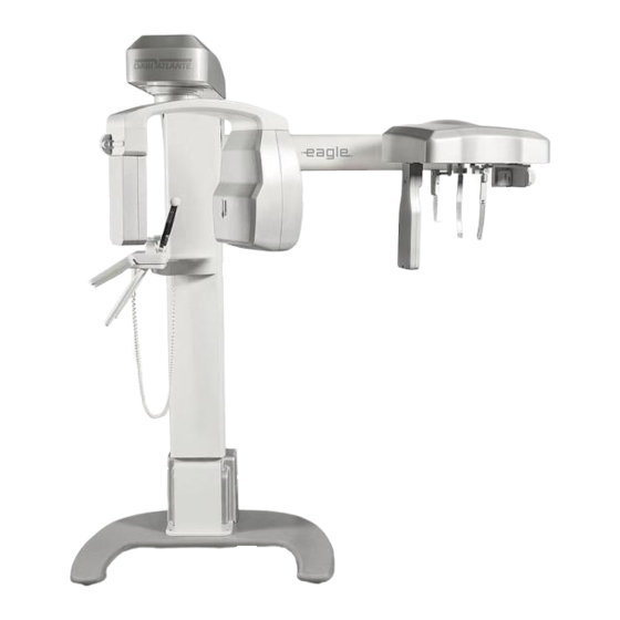
3.7. CAUTION IN CASE OF ABNORMAL EQUIPMENT FUNCTION In case the equipment shows abnormal heating, noise or any other type of abnormality, check if the problem is related to any of the items listed in this manual. If the problem cannot be solved, turn off the equipment and call for Authorized Technical Assistance. - Page 14 4. C COMPUT TERIZE ED TOMO OGRAP PHY SYS STEM O OVERVIE 1. DIGITAL L PAN-CB CT CONF IGURATIO The followin ng image sh hows the wh hole system without opt tional Ceph h arm mount ted. Mecha anism Rotatin ng Arm X-Ray y Tube Head...
- Page 15 2. DIGITAL L PAN-CB CT-CEPH CONFIGU URATION The followin ng image sh hows the wh hole system with option nal Ceph arm m mounted. ving Ceph halostat Mecha anism Rotatin ng Arm X-Ray T Tube Head Pan S Sensor lder Ceph h Sensor Holder...
- Page 16 3. DIGITAL L SNAP-O ON CONFIG GURATION The follo owing image e shows the whole syste em with opt tional Ceph arm mounte Moving Mechanism phalostat (Opt tional) Ceph halostat Arm Rotating Arm X-Ray T Tube Head SNAP-ON N Sensor NAP-ON Sens sor Holder...
- Page 17 4. DIGITAL L FIXED C CONFIGUR RATION The follo owing image e shows the e whole syst t em. No opt tional ceph arm is avail lable in this c configuratio Moving Mechanism Rotating Arm X-Ray Tu Head SNAP-ON N Sensor ead Support Control P Panel...
-
Page 18: Analog Configuration
5. ANALO G CONFIG GURATION The follo owing image e shows the whole syste em with opt tional Ceph arm mounte Moving Cephalostat Ar Mechanism Cephalostat ( (Optional) Rotating Ar X-Ra ay Tube Head Film m Holder Film Holder Ear rod Head Suppo Nose e Support... - Page 19 6. POWER R SUPPLY UNIT OPT TIONS The followin ng image sh hows the P Power Supp ply Unit op ptions that c can be used d in all confi igurations. Standard* Slim *Orde er on request 7. FREE S TANDING BASE (O PTIONAL)
-
Page 20: List Of Accessories
4. 8. LIST OF F ACCESS SORIES Bite G Guide Silicon n chin rest c cover Chin re est for CT Chin re est for patie ent with teet TMJ an nd Sinus no ose support Chin re est for patie ent without t teeth Head H... - Page 21 Nose Sup pport Carpus Su upport ALL PARTS S, ACCESS SORIES A AND OPTIO ONS DESC CRIBED IN N THIS OWNER'S M MANUAL AR RE FOR EX XCLUSIVE U USE. USE OF AN Y PARTS, ACCESSO ORIES OR M MATERIAL NOT SPEC CIFIED OR PROVI...
-
Page 22: Computer System
1. RECOM MMENDED SPECIFIC CATIONS It is imp perative that t this comp puter system m be dedica ated for the e Eagle 3D CBCT Mach hine. 1 – Recomm mended Com mputer Spec cifications Table 1 erating Syst tem Windo ows 7 Profes ssional –... - Page 23 2 - M Make sure th he network adapter is i installed. If f not, install the networ rk card driv ve using the C CD shipped w with the equ uipment. 3 - A After installa ation restart the compute To co onfigure the e network ca...
- Page 24 8 - Initia lly, this sett ting is disab bled. Chang ge the value e to 9014 by ytes and the en click 9 - Go to Settings Power Man nagement ta ab and unch heck all item 10 –...
- Page 25 3. SOFTW WARE INST TALLATIO Insert the e accompan nying media a and execu ute the Setu up.exe. The e following screen shoul ld be display yed. 1 – Selec ct the langua 2 - Press NEXT: 3 – Read carefully th he EULA an nd if you agr...
- Page 26 4 – Click k on the Che eckbox if yo ou want crea ate a desktop p icon and P Press NEXT 5 - Press INSTALL t to start the i installation. 6- The so oftware will install all re equired soft tware, pleas se wait until...
- Page 27 7 - Press FINISH to close the se etup. 8- After installation, , access Wi indows Star rt Menu / A All Programs s / Dental Im maging Softw ware/ Dental l Imaging S Software. Th he main soft tware windo ow should d display as fo ollows:...
- Page 28 A DIGITAL VERSION OF THE S SOFTWARE E USER MA ANUAL WI LL BE AVAILABLE E WITH TEC CHNICAL C CHARACTE ERISTICS A AND GUIDE ELINES ON THE SO FTWARE O OPERATION N THE AC CT OF PU RCHASE Y YOU WILL L RECEIVE E A SOFT...
-
Page 29: Imaging Programs
6. IMAGING PROGRAMS The Eagle 3D CBCT Machine contains a set of profiles. 6.1. PANORAMIC PROFILES: There are eight panoramic profiles available: from P1 to P6, P17 and P23: Program Description LCD Display Touch Screen Display Standard Panoramic: This exposure... - Page 30 beam more orthogonal in respect to the dental arch. Low Dosage Panoramic*: This exposure is the standard panoramic profile with faster execution lower dosage. The patient will receive less exposure, so as a result the overall image quality decreased. Child Panoramic: This exposure has a 15% size reduction...
- Page 31 proved thogonally tewing *: is exposur re is the bite ewing-like image ofile optimiz zed for the more orth hogonal in respect to dental arch 6.2. CEPHAL LOMETRIC C PROFILE ogram Descrip ption LCD Dis splay Touc ch Screen n Display Film C Cephalom metric:...
-
Page 32: Tomography Profile
Low Dosage Digital Cephalometric*: With this profile it is possible to execute a lateral ceph with a small exposure area and thus with a lower dose to the patient. 6.1. TOMOGRAPHY PROFILE Program Description Tomography: With this profile it is possible to select the interesting region and get 3D image and tomography cuts. -
Page 33: Control Panel
7. C CONTRO OL PAN 1. INTROD DUCTION The equi pment has a touch scr een display y with six bu uttons and also has im mportant inform mation of th he current st tatus of the machine to help the use er operate th he unit. - Page 34 Displays the selected patient ADULT / age (ADULT / CHILD ) to CHILD pre-select the kV. No selection Please be aware that the values of kV indicated are for reference only. Child selected Adult selected SMALL / MEDIUM / Displays the selected patient LARGE biotype Size not selected...
- Page 35 The anod dic current i s not user adjustabl le. The valu e indicated is optimu um for imag generatio on in each p rofile. Indication n that curren nt profile us 8mA of a anodic curre ent. TIME In all pro ofiles the val lue is not user adju...
- Page 36 The main n screen for r CBCT mo ode is shown n below. Sw wap the fun ctions by to ouching the sc creen. EXAM INFO SELEC CTION RESTART SELEC TION POSITION LASER MODE COLU ADJU OV ADJUST CHIN RE ADJUST POSURE...
- Page 37 FUNCTION DESCRIPTION EXPLANATION Select X-ray: Equipment is not ready to expose x- rays. If exposure switch is pressed the equipment will operate demonstration mode x-ray exposure). Displays current status of the INFO LINE machine. Ready to Expose! Equipment is ready to expose x-rays. Cooling: 00:30 Equipment is cooling down.
-
Page 38: Control Keys
3. CONTR ROL KEYS ) Membra ane keyboar Plus Key Used to i increase kV V, exposure time (for a analog ceph h), select p atient age (child and d adult), siz ze (small, m medium and large) and r radiography y type (i.e. - Page 39 Key Up C Chin Rest Used to i increase chi in rest heigh ht. The syst tem stops a automaticall ly when it reaches th he upper hei ight limit. Key Dow wn Chin R est: Used to d decrease chi in rest heigh ht.
- Page 40 4. CONTR ROL PANE EL INDICAT TING LIGH Exposur re-Signalin The LED at the cente er of the sym mbol will lig ght up durin ng x-ray exp posure. An audible w warning will also sound. 5. REMOT TE EXPOSU URE SWIT TCH (OPTI ONAL)
- Page 41 8. P PREPAR RING FO OR THE EXPOS SURE This section describes op perations re equired for e exposing im mages. This section describes th he steps requ uired before e positioning g the patien nt on the mac chine. 1.
-
Page 42: Before Positioning The Patient
8.2. BEFORE POSITIONING THE PATIENT Ask the patient to remove any glasses, hearing aids, dentures, and personal jewelry such as earrings, necklaces, and hairpins. If required, place a protective lead apron over the patient’s body, especially for pediatric patients. Always follow local regulation. 8.3. - Page 43 PATIENT AGE AND DENTAL DEVELOPMENTAL STAGE Child with Child with Adolescent with Adult, TYPE OF Primary Transitional Permanent Dentate or Dentition (prior Dentition (after Dentition (prior to ENCOUNTER Adult, Edentulous Partially to eruption of first eruption of first eruption of third Edentulous permanent tooth) permanent tooth)
- Page 44 assess develo oping third mola Patient with h other circumstan nces including, bu ut not imited to, prop posed or xisting implan nts, other Clinical judgme ent as to need for and type o of radiographi c images for e evaluation and d/or monitoring g of...
- Page 45 13. Evidence of foreign objects Factors increasing risk for caries may be assessed using the ADA Caries Risk Assessment forms (0 – 6 years of age and over 6 years of age). U.S. Department of Health and Human Services. Dental Radiographic Examinations: Recommendations for Patient Selection and Limiting Radiation Exposure.
- Page 46 9. P PANORA AMIC EX XPOSUR This section uses opera ation conce pts describe ed on prev ious section ns. Please r refer to those e sections w hen needed This procedu ure will pro oduce a ful l size pano oramic expo osure.
- Page 47 Before po ositioning th he patient, c completely o open the hea ad support. Select the e required p panoramic p rofile (from m P1 to P23) Select t the correct t exposure e paramete ers in acc cordance w with the patient chara...
- Page 48 9.2. P POSITION ING THE P PATIENT Guide the pa atient to the e unit in fron nt of the ch hin rest. If n necessary, a adjust the he eight of the un nit using the e Up and Do own keys of f the contro l panel.
- Page 49 Laser adju usting key If require ed, adjust th e image lay yer position using the pl lus and minu us key whil le in layer r positioning g mode on th he main scre een. HE LASER RS USED ON THE E EQUIPMEN NT ARE CL...
- Page 50 Press and ho old down th he exposure e button. T The machine e will first move to th he start positi ion and the en it will pr roceed with h the exposu ure. During g exposure, a visual LE ED and audib ble beeping...
- Page 51 9.4. E ETTINGS A AND DOSE E INFORM MATION The table e below sh hows the fa actory prog grammed pa arameters su uggested fo or each profil le based on n patient´s s size and ag ge as well a as the Dose Area Prod duct (DAP)
- Page 52 CEPH HALOME ETRIC E EXPOSU This section will occasi ionally use procedures s described in previous s sections. Please refer to those sec ctions when n needed. This procedu ure will prod duce a ceph alometric ex xposure as s selected: Waters PA Lateral...
- Page 53 ll out the fo orm with the e patient info formation, se elect the con nfiguration and profile. ress OK bef fore starting g the exposu ure. The soft ftware will s start a 150-s second coun ntdown. Durin ng the count tdown take an exposure 10.2...
- Page 54 10.3 . TAKING G A CEPHA ALOMETR RIC EXPOS SURE When "Read dy to Expo ose" is show wn on the display the e system is ready to t take an expos sure. Move to a pr rotected area a without lo osing direct eye contact with the pa...
- Page 55 10.4. SETTINGS AND DOSE INFORMATION The table below shows the factory programmed parameters suggested for each profile based on patient´s size and age as well as the Dose Area Product (DAP) for the parameter combinations. The dose area product (DAP) meter is a measure of dose in Gray multiplied by the area irradiated.
- Page 56 Dose Area P Product (mGy. .cm²) ildren Adult Exposure Current Profile Time (s) (mA) Small Medium arge Small Medium Large 75 kV 77.5 kV 0 kV 80 kV V 82.5 kV 85 kV 16.5 8 27.3 28.8 30.4 30.4 32.0 33.6 gital Ceph. 10.0 8 16.5 17.5 18.4 ...
- Page 57 TOMO OGRAPH This section will occasi ionally use procedures s described in previous s sections. Please refer to those sec ctions when n needed. This procedu ure will prod duce tomogr raphic imag ges. To do this us se the chin r rest support and head su upport.
- Page 58 ll out the fo orm with th he patient in nformation, select the F FOV config guration, mo ode and mA. A After that se elect the po sition of the e FOV and p press OK. No a area selected Area selected 11.2 .
- Page 59 Head d positione ead Holder hin rest Before po ositioning th he patient fu ully open he ead position ner. Ask the p patient to re est his chin against the e chin rest. Adjust the height of th he head holde er and secur re firmly usi...
- Page 60 Make e sure the vo olume posit tion is correc ct. If necess sary adjust i its position. 11.3 . TAKING G A TOMO GRAPHIC C EXPOSU When "Read dy to Expo ose" is show wn on the display the e system is ready to t take an...
-
Page 61: Settings And Dose Information
The exposure switch is a dead-man like switch. If released, the x-ray exposure will stop immediately. Otherwise, after the rotation has completed and audible beeping stops you may release the exposure switch. Upon completion of the exposure, the arm will rotate to the patient exit position. At this point, you may guide the patient out of the machine. - Page 62 Dose Ar rea Product (m mGy.cm²) 85 kV @ 8 mA A 5x5 6x8 8x8 ‐ 8 8x12 ‐ 8x16 FOV Mode LD STD HD LD TD HD UHD LD STD HD UHD Time (s s) 16.5 20.5 25.5 32.0 16.5 0.5 25.5 32.0 16.5 20.5 25.5 32.0 DAP (mGy.c cm²) 776.8 ...
-
Page 63: Cleaning
PROC CEDURE ES FOR R REUSE 12.1 . CLEANI Using a cle ean moist c loth produc ct, clean the e equipmen nt’s surface such as th he head positioner, p patient hand dles, nose s support, sili icon chin re est cover, c chin rest, ea ar rods,... -
Page 64: Troubleshooting Guide
13. TROUBLESHOOTING GUIDE 13.1. UNIT OPERATION PROBLEM Symptom Possible Cause Action required Wait for mains voltage to be Mains voltage not available available. Power supply cable is unplugged from back of Plug it into the equipment equipment Power supply cable is Plug it into the wall socket Equipment does not turn on unplugged from wall socket... - Page 65 13.2 . PATIEN NT POSITIO ONING PR ROBLEM The stand dard panora amic image i is showed b below. A error in n the patient t positioning g may gener rate several failures in the image. Sympt Possible Cau Acti ion require Head til lted patient.
- Page 66 Sympt Possible Cau Acti ion require The pati ient's head r rotated. teeth ppear Check the e position of the Patient position for r posterior ampl ified on on ne side an sagittal pla ane of the patient teeth in n relation to o the focal narro...
- Page 67 Sympt Possible Cau Acti ion require Adjust the e focal plane e of the Inciso ors and cani ines wide Position n of the arch is equipment t by posi itioning posterio or of the foc al plane. the Canine e red laser on the and u...
- Page 68 Sympt Possible Cau Acti ion require Reposition patient A row w of flat te eeth. Unabl relying o on the Fr rankfurt to see e the roots of the uppe er Patient's s head is tilt ted back plane laser teeth Sympt Possible Cau...
- Page 69 Sympt Possible Cau Acti ion require Anterior r teeth be ehind the Adjust the e focal pla ane by focal pla Inciso ors and ca anines teet positioning g the Cani ine red blurre Anterior r teeth ahe ead of the laser on Ca anine tooth.
- Page 70 Sympt Possible Cau Acti ion require Reverse th he patient's h hands The p patient's sho oulders touc Patient i is too large for the on the pati ient handles : Left the X X-ray head o or digital unit on the righ ht side and v vice-...
- Page 71 QUAL LITY AS SSURAN This section will occasi ionally use procedures s described in previous s sections. Please refer to those sec ctions when n needed. n order to a assure imag e quality of f the equipm ment, Quali ity Assuranc ce (QA) Ph hantoms...
- Page 72 The Q QA phantom ms are show w below. QA Pha antom for Sm all FOV* QA Ph hantom for La arge FOV* *Not included d. Order on r equest Theses QA p phantoms c ontain two s sections des sign to meas surement of f all paramet...
- Page 73 The follow s screen will b be opened Fill the fiel lds with the e informatio on required d and select t the desire ed diagnosi s to be perfo ormed. You can select m more than on ne diagnosis s.
-
Page 74: Beam Position
14.2 . QA DIAG GNOSIS F FOR PANO ORAMIC This procedu ure will pro oduce panor amic image 14.2. 1. BEAM P POSITION The softwar re will indic ate that the beam positi ion will be c checked. Remove the e chin rest su upport. - Page 75 14.2. 2. CALIBR RATION The softwar re will indic ate that the calibration will be chec cked. Place the QA A Phantom for Panoram mic on chin rest suppor rt and level i Phantom for r Panoramic When it´s re eady press O OK, the soft ftware will s...
- Page 76 14.2. 3. MAXIM MUM CONT TRAST RE ESOLUTIO The softwar re will indic ate that the maximum c contrast reso olution will be checked Remove the e Top part of f the QA Ph hantom for P Panoramic f from the sup pport and pl lace the Reso...
- Page 77 14.3 . QA DIAG GNOSIS F FOR CEPH HALOMETR This procedu ure will pro oduce cepha alometric im mages. 14.3. 1. BEAM P POSITION The softwar re will indic ate that the beam positi ion will be c checked. Remove the e chin rest s support, ope en the head...
- Page 78 Calibrati ion Check for r Cephalomet tric 14.3. 3. MAXIM MUM CONT TRAST RE ESOLUTIO The softwar re will indic ate that the maximum c contrast reso olution will be checked Remove the e chin rest s support, ope en the head holder.
- Page 79 Carpal suppor rt position solution Test P Phantom When it´s re eady press O OK, the soft ftware will s start a 150-s second coun ntdown. Dur ring the count tdown take an exposure e. The softw ware will sho ow a picture e below.
- Page 80 Verify if the e lines of the e contrast el lement are v visible. 14.4 . QA DIAG GNOSIS F FOR TOMO OGRAPHY 14.4. 1. PREPAR RING X-RA AY UNIT This procedu dure will pro oduce tomog graphic ima ges. It will b be necessar ry take an ex xposure...
- Page 81 Water Repe eat the proce edure above 14.4. 2. CONTR RAST SCAL CT numb bers, also ca alled (HU) H Hounsfield Units, repre esent the att tenuation va alues of X-Ra ay passing th hrough a va ariety of mat terial densit ties.
- Page 82 ise and Unifo ormity Section After the calculation n of the unifo formity, and using same e flat-field im mage (slice) ), the softw ware evaluat tes the noise e power spec ctrum (NPS S). The NPS is defined a 〈| 〉...
- Page 83 For calcu ulation of th he MTF the software w will use the Slanted-Ed ge MTF tec chnique that i is an edge g gradient MT TF method specifically y suited to M MTF calcula ations for sp patially samp pled capture devices.
- Page 84 Access Tools Dose measurement Insert all values into the software to generate a report that can be saved to compare the results to previous or optimum values.
- Page 85 14.6 . QA REP PORT After dia agnosis the software wi ill create a QA report that can be saved to co ompare the re esults to pre evious or op timum valu ues. An exam mple of this report is sh hown below...
- Page 86 15. INSTALLATION, INSPECTION AND MAINTENANCE 15.1. INSTALLATION This equipment must be installed by authorized service technicians from Alliage because only he/she has the tools, information, and training needed to perform this task. 15.2. PERIODIC INSPECTION It is imperative that this equipment be inspected regularly to ensure the operational safety and functional reliability.
- Page 87 Membrane k keyboard Operatio on/Damage Annu Laser Operatio on/ Intensity Annu Accesso ries Gener ral damages s that may ca ause risk Annu Dose measur rements Perfo ormance Annu Recommen ndation acco ording ICRP P Publicatio on 129 Refer to pro ocedures de scribed in it tem 14.
- Page 88 16. DISPOSAL OF THE UNIT 16.1. ENVIRONMENTAL CONTAMINATION In order to prevent environmental contamination or improper disposal of the Eagle 3D Computerized Tomography Machine, the equipment must be disposed of (according to local, state, or federal regulations) at an appropriate site. The equipment contains materials and solutions listed below which, upon completion of its useful life, must be disposed of at the appropriate sites.
- Page 89 – Address Ribeirão o Preto/SP – – Brazil CEP P 14097-500 ference typ Compute erized Tom mography Model Eagle 3D Equip pment class ification acc cording to F Class sification cla ass (risk clas CLAS S II Equip pment class...
- Page 90 17.3. RADIOLOGICAL INFORMATION General Information Exposure time accuracy ±10 % Maximum operation factor 1 : 25s Tube voltage (kVp) Adjustable from 60 to 85 kVp, 2.5 steps. Accuracy at the kVp value ± 10 % Accuracy at the anodic current value ±...
- Page 91 X-Ray y machine w with radiolog gic protectio on according g to NBR IE EC 60601-1- -3:2001. X-Ray y generator r Eagle 3D NBR IEC 60 0601-2-7:19 X-Rad diation-emit tting set EA GLE 3D NB BR IEC 6060 01-2-28:200 Radio...
- Page 92 17.5 X-RAY TUBE 17.5. 1. SPECIFI ICATIONS Manu ufacturer TOSH HIBA Mode D-054 Focus s size 0.5 – – IEC 60336 Equiv valent filtrati 0.003 3 ft Al equiv Anod e angle 5º Anod e material Tung gsten Maxim mum voltage 100 k Therm mal capacity...
- Page 94 17.6. EQUIPMENT TESTED ACCORDING STANDARDS EN 60601-1 (1990); Amendment 1 EN 60601-1 (1992); Amendment 2 EN 60601-1 (1995); Amendment13 EN 60601-1 (1995); UL 60601- 60601-1-4-2004 EN 60601-1-3 (2001); EN 60601-2-7 (2001); EN 60601-2-28 (2001); EN 60601-2-32 (2001); IEC 60601-1; Emenda 1 IEC 601-1; IEC 60601-1-2;...
- Page 98 17.7 . MAXIMU UM SYMM ETRICAL RADIATIO ON FIELD 17.7. 1. IRRADI IATED FIE ELD SIZE – – ANALOG G AND DIG GITAL PAN NORAMIC AM (PAN: A ADULT AN ND CHILD D – TMJ – M MAXILLAR RY SINUS 17.7.
- Page 99 17.7. 3. IRRADI IATED FIE ELD SIZE – – ANALOG G CEPH - L LATERAL EXAM 17.7. 4. IRRADI IATED FIE ELD SIZE – – ANALOG G CEPH - F FRONTAL L EXAM...
- Page 100 17.7. 5. IRRADI I ATED FIE E LD SIZE – – TOMOGR R APHIC E E XAM:...
- Page 101 17.8. ELECTROMAGNETIC EMISSIONS Manufacturer’s guidelines and declaration - electromagnetic emissions The EAGLE 3D Computerized Tomography Machine is intended for use in the electromagnetic environment specified below. Should the buyer or user of the EAGLE 3D Computerized Tomography Machine ensure that it is used in such an environment.
- Page 102 Note: Ut is the mains supply AC voltage prior to the application of the assay level. Manufacturer’s guidelines and declaration - electromagnetic immunity The EAGLE 3D Computerized Tomography Machine has been designed for use in electromagnetic environments according to the specifications below. The client or X-Ray Machine operator must ensure that the equipment is used in such type of environment.
- Page 103 I If the meas surement o of the field intensity on n the site w where the EAGLE 3D Comp puterized T Tomography y Machine is used ex xceeds the applicable RF comp liance leve...
- Page 104 recom mmended separation n distance d in mete ers (m) ca n be deter rmined by using the equat tion applic cable for the trans smitter’s fr requency, where P is the tra ansmitter’s maxim mum nom minal outp put power r in watts s (W) ac ccording t...
- Page 105 IDENT TIFICAT TION LA ABELS 18.1 PACKA...
- Page 106 18.2 . PRODU U CT...
- Page 107 EQUIP PMENT DIMENS SIONS * Pow wer supply u unit slim...
- Page 108 20. WARRANTY The Warranty Certificate should be completed by the Authorized Technical Alliage and one copy must be left with owner to prove the equipment warranty. The remaining copies will be send to the Distributor and to the factory. The warranty is limited to repair or replacement of parts with manufacturing defects, not including the repair of defects originating in: - Failure to observe the operating and maintenance instructions;...
Need help?
Do you have a question about the Eagle 3D and is the answer not in the manual?
Questions and answers