Table of Contents
Advertisement
Quick Links
Advertisement
Table of Contents

Related Manuals for Dabi Atlante EAGLE 3D


Summary of Contents for Dabi Atlante EAGLE 3D
-
Page 2: Table Of Contents
TABLE OF CONTENTS INTRODUCTION ..........................5 SYMBOLS ............................6 WARNINGS AND PRECAUTIONS ....................8 3.1. WARNINGS AND/OR CAUTION DURING TRANSPORTATION AND STORAGE ......8 3.2. TRANSPORTATION OR STORAGE ENVIRONMENTAL CONDITIONS ..........8 3.3. OPERATIONAL ENVIRONMENTAL CONDITIONS ................ 8 3.4. INSTALLED EQUIPMENT CONDITIONS BETWEEN OPERATIONS ..........8 3.5. - Page 3 7.3. CONTROL KEYS......................... 36 7.4. CONTROL PANEL INDICATING LIGHTS ..................38 7.5. REMOTE EXPOSURE SWITCH (OPTIONAL) ................38 PREPARING FOR THE EXPOSURE ....................39 8.1. TURNING THE EQUIPMENT ON ....................39 8.2. BEFORE POSITIONING THE PATIENT ..................40 8.3. RECOMMENDATIONS FOR PEDIATRIC EXAMINATIONS ............40 PANORAMIC EXPOSURES ......................
- Page 4 14.4. QA DIAGNOSIS FOR TOMOGRAPHY ..................77 14.4.1. PREPARING X-RAY UNIT ....................... 77 14.4.2. CONTRAST SCALE ......................... 78 14.4.3. NOISE AND UNIFORMITY ..................... 79 14.4.4. SLICE THICKNESS ........................80 14.4.5. HIGH CONTRAST SPATIAL RESOLUTION ................80 14.4.6. LOW CONTRAST DETECTABILITY ..................80 14.5.
- Page 5 Attention For greater safety: Read and understand all instructions written in this manual before installation or use of the equipment. This instruction manual should be read by all operators of the equipment. This instruction manual was originally written in Portuguese. Intended Use Intended for dental radiographic examination and diagnosis of diseases of the teeth, jaw and oral structures.
-
Page 6: Introduction
1. INTRODUCTION The Eagle 3D Machine is a complete 3-in-1 system for dental imaging capable of: Analog Panoramic Profiles Analog Cephalometric Profiles Digital Panoramic Profiles Digital Cephalometric Profiles CBCT Profiles The digital machines use a digital sensor and auto image processing that allow a speed up the diagnostic and improve the clinic workflow. -
Page 7: Symbols
2. SYMBOLS Use the icons below to identify the symbols on your equipment. Fragile, handle with Stacking limit by number care Keep away from rain Temperature limit This way up Humidity limitation Keep away from Center of gravity sunlight Do not walk or stand Electrostatic Sensitive here Devices (ESD) - Page 8 (power: disconnect from (power: connect to the the main switch) main switch) Emission of ionizing Caution radiation Warning; General warning High voltage Warning; Warning; Crushing of hands Ionizing radiation Warning; Action required Laser diode...
-
Page 9: Warnings And Precautions
3. WARNINGS AND PRECAUTIONS 3.1. WARNINGS AND/OR CAUTION DURING TRANSPORTATION AND STORAGE The equipment must be transported and stored by observing the following: Care should be taken to prevent falls and impact. The arrows must be pointing upwards. ... -
Page 10: Additional Procedures Prior To Equipment Use
3.5. ADDITIONAL PROCEDURES PRIOR TO EQUIPMENT USE Even prior to its first use, the equipment must be cleaned and disinfected; the same additional procedures must be followed for reuse, as described in Chapter 0. 3.6. WARNINGS AND/OR CAUTION TO BE ADOPTED 3.6.1. -
Page 11: Warning And/Or Caution After Equipment Use/Operation
Do not replace any equipment parts. Do not disconnect the cable or other connections unnecessarily. The Eagle 3D CT Scanner must be off when other equipment such as an electric scalpel or other similar devices are being used. ... -
Page 12: Precautions To Reduce Environmental Impact
3.7. PRECAUTIONS TO REDUCE ENVIRONMENTAL IMPACT Alliage S/A aims to achieve an environmental policy to promote supply of environmentally conscious medical and dental products that continuously minimize environmental impact and that are friendlier to the environment and human health. maintain minimal impact environment,... -
Page 13: Computerized Tomography System Overview
4. COMPUTERIZED TOMOGRAPHY SYSTEM OVERVIEW 4.1. DIGITAL PAN-CBCT CONFIGURATION The following image shows the whole system without optional Ceph arm mounted. Moving Mechanism Rotating Arm X-Ray Tube Head Pan Sensor Sensor Holder CBCT Sensor Sensor Holder Control Panel Head Holder Patient Handles Column Base (optional) -
Page 14: Digital Pan-Cbct-Ceph Configuration
4.2. DIGITAL PAN-CBCT-CEPH CONFIGURATION The following image shows the whole system with optional Ceph arm mounted. Moving Cephalostat Mechanism Rotating Arm X-Ray Tube Head Pan Sensor Holder Ceph Sensor Holder Control Panel CBCT Sensor Patient Handles Holder Ear Rods Head Support Nose Support Secondary Collimator... -
Page 15: Digital Snap-On Configuration
4.3. DIGITAL SNAP-ON CONFIGURATION The following image shows the whole system with optional Ceph arm mounted. Moving Mechanism Cephalostat (Optional) Cephalostat Arm Rotating Arm X-Ray Tube Head SNAP-ON Sensor SNAP-ON Sensor Holder Ear rods Head Support Nose Support Control Panel Secondary Collimator Patient Handles... -
Page 16: Digital Fixed Configuration
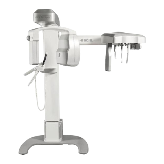
4.4. DIGITAL FIXED CONFIGURATION The following image shows the whole system. No optional ceph arm is available in this configuration. Moving Mechanism Rotating Arm X-Ray Tube Head SNAP-ON Sensor Head Support Control Panel Patient Handles Column Base (optional) -
Page 17: Analog Configuration
4.5. ANALOG CONFIGURATION The following image shows the whole system with optional Ceph arm mounted. Moving Cephalostat Arm Mechanism Cephalostat (Optional) Rotating Arm X-Ray Tube Head Film Holder Film Holder Ear rods Head Support Nose Support Control Panel Patient Handles Column Base (optional) Packages of the Panoramic X-Ray Eagle are made of wood, cardboard,... -
Page 18: Power Supply Unit Options
4.6. POWER SUPPLY UNIT OPTIONS The following image shows the Power Supply Unit options that can be used in all configurations. Standard* Slim *Order on request 4.7. FREE STANDING BASE (OPTIONAL) The following image shows the optional Free Standing Base. The equipment will be fixed to the base and wall by an authorized technician during installation. -
Page 19: List Of Accessories
4.8. LIST OF ACCESSORIES Bite Guide Silicon chin rest cover Chin rest for CT Chin rest for patient with teeth TMJ and Sinus nose support Chin rest for patient without teeth Head Holder acrylic bars Head Holder... - Page 20 Nose Support Carpus Support ALL PARTS, ACCESSORIES AND OPTIONS DESCRIBED IN THIS OWNER'S MANUAL ARE FOR EXCLUSIVE USE. USE OF ANY PARTS, ACCESSORIES OR MATERIAL NOT SPECIFIED OR PROVIDED IN THIS OWNER'S MANUAL IS USER'S FULL RESPONSIBILITY.
-
Page 21: Computer System
5. COMPUTER SYSTEM 5.1. RECOMMENDED SPECIFICATIONS It is imperative that this computer system be dedicated for the Eagle 3D CBCT Machine. Table 1 – Recommended Computer Specifications Windows 7 Professional – 64-bit Operating System Windows 8 Professional Windows 8.1 Professional Windows 10 Professional Intel ®... - Page 22 2 - Make sure the network adapter is installed. If not, install the network card drive using the CD shipped with the equipment. 3 - After installation restart the computer. To configure the network card, follow the procedure: 1 - Go to Control Panel Network Internet and Network Connections 2 - Click the right mouse button on the connection DESKTOP Intel Gigabit CT, and visit the properties.
-
Page 23: Software Installation
9 - Go to Settings Power Management tab and uncheck all items. 10 – Select Internet Protocol TCP/IP Version Proprieties 11 – Define the IP address 192.168.5.10 and Subnet Mask 255.255.255.0 5.3. SOFTWARE INSTALLATION Insert the accompanying media and execute the Setup.exe. The following screen should be displayed. - Page 24 1 – Select the language 2 - Press NEXT: 3 – Read carefully the EULA and if you agree select “ I accept the agreement” and press NEXT 4 – Click on the Checkbox if you want create a desktop icon and Press NEXT...
- Page 25 5 - Press INSTALL to start the installation. 6- The software will install all required software, please wait until if finish.
- Page 26 7 - Press FINISH to close the setup. 8- After installation, access Windows Start Menu / All Programs / Dental Imaging Software/ Dental Imaging Software. The main software window should display as follows:...
- Page 27 A DIGITAL VERSION OF THE SOFTWARE USER MANUAL WILL BE AVAILABLE WITH TECHNICAL CHARACTERISTICS AND GUIDELINES ON THE SOFTWARE OPERATION. IN THE ACT OF PURCHASE YOU WILL RECEIVE A SOFTWARE MANUAL, WHERE TO FIND ALL INFORMATION AND TECHNICAL FEATURES.
-
Page 28: Imaging Programs
6. IMAGING PROGRAMS The Eagle 3D CT Scanner contains a set of profiles. 6.1. PANORAMIC PROFILES: There are eight panoramic profiles available: from P1 to P6, P17 and P23: Program Description LCD Display Touch Screen Display Standard Panoramic: This exposure... - Page 29 Low Dosage Panoramic*: This exposure is the standard panoramic profile with faster execution and lower dosage. The patient will receive less exposure, so as a result overall image quality decreased. Child Panoramic: This exposure has a size reduction with respect to the standard panoramic profile.
-
Page 30: Cephalometric Profiles
Improved Orthogonally Bitewing *: This exposure is the bitewing-like image profile optimized for the beam to be more orthogonal in respect to the dental arch. 6.2. CEPHALOMETRIC PROFILES Program Description LCD Display Touch Screen Display Film Cephalometric: With this profile possible to execute the following images: ... -
Page 31: Tomography Profile
with a lower dose to the patient. 6.1. TOMOGRAPHY PROFILE Program Description Tomography: With this profile it is possible to select the interesting region and get 3D image and tomography cuts. Fast Scout: With this profile it is possible to make a fast lateral image to position the patient before the tomography image. -
Page 32: Control Panel
7. CONTROL PANEL 7.1. INTRODUCTION The equipment has a touch screen display with six buttons and also has important information of the current status of the machine to help the user operate the unit. 7.2. MAIN SCREEN The main screen for panoramic and ceph mode is shown below. Swap the functions by touching the screen. - Page 33 ADULT / Displays the selected CHILD patient age (ADULT / CHILD ) to pre-select the No selection Please be aware that the values of kV indicated are for reference only. Child selected Adult selected SMALL / MEDIUM / LARGE Displays the selected patient biotype Size not selected (SMALL/MEDIUM/LARGE)
- Page 34 The anodic current is not user adjustable. The value indicated is optimum for image generation in each Indication that current profile uses profile. 8mA of anodic current. TIME In all profiles the value is not user adjustable. Value indicating that current profile has 14 seconds of x-ray exposure.
- Page 35 The main screen for CBCT mode is shown below. Swap the functions by touching the screen. EXAM INFO SELECTION RESTART POSITION SELECTION LASER MODE COLUMN ADJUST CHIN REST FOV ADJUST ADJUST EXPOSURE TIME...
- Page 36 FUNCTION DESCRIPTION EXPLANATION Select X-ray: Equipment is not ready to expose x-rays. exposure switch pressed the equipment will operate in demonstration mode (no x-ray exposure). Displays current status of INFO LINE the machine. Ready to Expose! Equipment is ready to expose x- rays.
-
Page 37: Control Keys
7.3. CONTROL KEYS a) Membrane keyboard Plus Key: Used to increase kV, exposure time (for analog ceph), select patient age (child and adult), size (small, medium and large) and radiography type (i.e. standard panoramic and low dosage). Minus Key: Used to decrease kV, exposure time (for analog ceph), select the patient age (child and adult), size (small, medium and large) and radiography type. - Page 38 Key Up Chin Rest: Used to increase chin rest height. The system stops automatically when it reaches the upper height limit. Key Down Chin Rest: Used to decrease chin rest height. The system stops automatically when it reaches the lower height limit. Laser key: Used to turn on/off positioning lasers: Mid-Sagittal, Frankfurt and Image layer Position (Canine).
-
Page 39: Control Panel Indicating Lights
7.4. CONTROL PANEL INDICATING LIGHTS Exposure-Signaling: The LED at the center of the symbol will light up during x-ray exposure. An audible warning will also sound. 7.5. REMOTE EXPOSURE SWITCH (OPTIONAL) A remote exposure switch installed outside of the radiation exposure room is available upon request or as required by state or country. -
Page 40: Preparing For The Exposure
8. PREPARING FOR THE EXPOSURE This section describes operations required for exposing images. This section describes the steps required before positioning the patient on the machine. 8.1. TURNING THE EQUIPMENT ON THE UNIT IS CONFIGURED FOR A LINE VOLTAGE DURING INSTALLATION BY THE TECHNICIAN ONLY. -
Page 41: Before Positioning The Patient
8.2. BEFORE POSITIONING THE PATIENT Ask the patient to remove any glasses, hearing aids, dentures, and personal jewelry such as earrings, necklaces, and hairpins. If required, place a protective lead apron over the patient’s body, especially for pediatric patients. Always follow local regulation. 8.3. - Page 42 PATIENT AGE AND DENTAL DEVELOPMENTAL STAGE Adolescent Child with Child with with Transitional Adult, TYPE OF Primary Permanent Dentition (after Dentate or Adult, ENCOUNTER Dentition (prior to Dentition Partially Edentulous eruption of first eruption of first (prior to permanent Edentulous permanent tooth) eruption of tooth)
- Page 43 exam to assess developing third molars Patient with other circumstances including, but not limited to, proposed or existing implants, other dental and Clinical judgment as to need for and type of radiographic images for evaluation and/or craniofacial pathoses, monitoring of these conditions restorative/endodontic needs, treated periodontal disease...
- Page 44 head and neck 13. Evidence of foreign objects Factors increasing risk for caries may be assessed using the ADA Caries Risk Assessment forms (0 – 6 years of age and over 6 years of age). U.S. Department of Health and Human Services. Dental Radiographic Examinations: Recommendations for Patient Selection and Limiting Radiation Exposure.
-
Page 45: Panoramic Exposures
9. PANORAMIC EXPOSURES This section uses operation concepts described on previous sections. Please refer to those sections when needed. This procedure will produce a full size panoramic exposure. If the child program is selected, the width and height of the exposed area will be slightly reduced. -
Page 46: Getting The Software Ready
Before positioning the patient, completely open the head support. Select the required panoramic profile (from P1 to P23). Select the correct exposure parameters in accordance with the patient characteristics. 9.1. GETTING THE SOFTWARE READY Open the Imaging software and make sure the green light is on before start. Press New Pan. -
Page 47: Positioning The Patient
9.2. POSITIONING THE PATIENT Guide the patient to the unit in front of the chin rest. If necessary, adjust the height of the unit using the Up and Down keys of the control panel. For a patient with teeth, ask them to step forward, grasp the patient handles, stretch up and bite the bite guide. -
Page 48: Taking A Panoramic Exposure
Laser adjusting key If required, adjust the image layer position using the plus and minus key while in layer positioning mode on the main screen. THE LASERS USED ON THE EQUIPMENT ARE CLASS I LASERS INDICATING THAT THE POWER OUTPUT IS MINIMAL. HOWEVER, AS GOOD PRACTICE, AVOID INTENTIONALLY EXPOSING USER AND PATIENT EYES TO THE LASER BEAM. - Page 49 Press and hold down the exposure button. The machine will first move to the start position and then it will proceed with the exposure. During exposure, a visual LED and audible beeping will indicate the presence of x-ray emission. The exposure switch is a dead-man like switch. If released, the x-ray exposure will stop immediately.
-
Page 50: Ettings And Dose Information
9.4. ETTINGS AND DOSE INFORMATION The table below shows the factory programmed parameters suggested for each profile based on patient´s size and age as well as the Dose Area Product (DAP) for the parameter combinations. The dose area product (DAP) meter is a measure of dose in Gray multiplied by the area irradiated. -
Page 51: Cephalometric Exposure
10. CEPHALOMETRIC EXPOSURE This section will occasionally use procedures described in previous sections. Please refer to those sections when needed. This procedure will produce a cephalometric exposure as selected: Waters PA Lateral Basal-Hirtz axial 45 degrees Carpal BEFORE START, OPEN THE HEAD POSITIONER AND REMOVE THE CHIN REST AND BITE GUIDE FROM THE PATIENT SUPPORT. -
Page 52: Positioning The Patient
Fill out the form with the patient information, select the configuration and profile. Press OK before starting the exposure. The software will start a 150-second countdown. During the countdown take an exposure. 10.2. POSITIONING THE PATIENT Guide the patient to the unit in front of the ceph arm rest. Adjust the height of the unit using the UP and DOWN keys on the control panel or ceph head as necessary. - Page 53 The exposure switch is a dead-man like switch. If released, the x-ray exposure will stop immediately. Otherwise, after the rotation has completed and audible beeping stops you may release the exposure switch. Upon completion of the exposure, the arm will rotate to the patient exit position.
-
Page 54: Settings And Dose Information
10.4. SETTINGS AND DOSE INFORMATION The table below shows the factory programmed parameters suggested for each profile based on patient´s size and age as well as the Dose Area Product (DAP) for the parameter combinations. The dose area product (DAP) meter is a measure of dose in Gray multiplied by the area irradiated. - Page 55 Dose Area Product (mGy.cm²) Children Adult Exposure Current Profile Time (s) (mA) Small Medium Large Small Medium Large 75 kV 77.5 kV 80 kV 80 kV 82.5 kV 85 kV 16.5 27.3 28.8 30.4 30.4 32.0 33.6 Digital Ceph. 10.0 16.5 17.5 18.4...
-
Page 56: Tomography
11. TOMOGRAPHY This section will occasionally use procedures described in previous sections. Please refer to those sections when needed. This procedure will produce tomographic images. To do this use the chin rest support and head support. Chin rest for tomography exposure 11.1. -
Page 57: Positioning The Patient
Fill out the form with the patient information, select the FOV configuration, mode and mA. After that select the position of the FOV and press OK. No area selected Area selected 11.2. POSITIONING THE PATIENT Guide the patient to the unit in front of the chin rest. If necessary, adjust the height of the unit using the Up and Down keys of the display. - Page 58 Head positioner Head Holder Chin rest Before positioning the patient fully open head positioner. Ask the patient to rest his chin against the chin rest. Adjust the height of the head holder and secure firmly using the tape. Make sure that the patient is immobilized.
-
Page 59: Taking A Tomographic Exposure
Make sure the volume position is correct. If necessary adjust its position. 11.3. TAKING A TOMOGRAPHIC EXPOSURE When "Ready to Expose" is shown on the display the system is ready to take an exposure. Move to a protected area without losing direct eye contact with the patient. KEEP CONSTANT EYE CONTACT WITH THE PATIENT AND ASSURE HE/SHE HAS BOTH HANDS DOWN DURING THE PROCESS. -
Page 60: Settings And Dose Information
Upon completion of the exposure, the arm will rotate to the patient exit position. At this point, you may guide the patient out of the machine. After a fell seconds the rotating arm will rotate to the start position for the next patient. - Page 61 Dose Area Product (mGy.cm²) 85 kV @ 8 mA 8x8 - 8x12 - 8x16 Mode Time (s) 16.5 20.5 25.5 32.0 16.5 20.5 25.5 32.0 16.5 20.5 25.5 32.0 1258. 1562. 1486. 1846. (mGy.cm²) 776.8 965.1 *Due to measurement errors and variation of equipment, consider a tolerance of DAP VALUES VARY FROM UNIT TO UNIT IN RELATION TO THE X- RAY TUBE OUTPUT.
-
Page 62: Procedures For Reuse
12. PROCEDURES FOR REUSE 12.1. CLEANING Using a clean moist cloth product, clean the equipment’s surface such as the head positioner, patient handles, nose support, silicon chin rest cover, chin rest, ear rods, temple stabilizers on a regular basis. ... -
Page 63: Troubleshooting Guide
13. TROUBLESHOOTING GUIDE 13.1. UNIT OPERATION PROBLEM Symptom Possible Cause Action required Mains voltage not Wait for mains voltage to available be available. Power supply cable is unplugged from back of Plug it into the equipment equipment Power supply cable is Equipment does not turn unplugged from wall Plug it into the wall socket... -
Page 64: Patient Positioning Problem
13.2. PATIENT POSITIONING PROBLEM The standard panoramic image is showed below. A error in the patient positioning may generate several failures in the image. Symptom Possible Cause Action required Head tilted patient. The teeth appear more Check the position of the Patient position to tune in amplified on one side and sagittal... - Page 65 narrower on the other. Patient position patient with the laser line posterior teeth in relation to the focal plane Head turned to the right Head turned to the left Symptom Possible Cause Action required Adjust the focal plane of Incisors canines equipment Position of the arch is...
- Page 66 Adjust the focal plane of Position of the arch is equipment Incisors and canines wide posterior focal positioning the Canine red and unsharp. plane. laser on the tooth Canine tooth. Symptom Possible Cause Action required A row of teeth is bent upwards.
- Page 67 Reposition patient A row of flat teeth. Unable Patient's head is tilted relying on the Frankfurt to see the roots of the back plane laser upper teeth. Symptom Possible Cause Action required Ask the patient to take a Patient neck step forward and stretch Central area of the image stretched...
- Page 68 Symptom Possible Cause Action required Anterior teeth behind the Adjust the focal plane by focal plane Incisors and canines teeth positioning the Canine red blurred. Anterior teeth ahead of laser on Canine tooth. the focal plane Anterior teeth behind the focal plane Anterior teeth ahead of the focal plane Symptom Possible Cause...
- Page 69 Symptom Possible Cause Action required The patient's shoulders Reverse the patient's touch the X-ray head or Patient is too large for the hands on the patient digital sensor / cassette unit handles: Left on the right holder. side and vice-versa The inclination of the Check the positioning of patient's head is not...
-
Page 70: Quality Assurance
QUALITY ASSURANCE This section will occasionally use procedures described in previous sections. Please refer to those sections when needed. In order to assure image quality of the equipment, Quality Assurance (QA) Phantoms will be provided (Reference 21CFR 1020.33 (d)(1)) to test of the system performance and quality. -
Page 71: Initial Procedure
QA Phantom for Small FOV* QA Phantom for Large FOV* *Not included. Order on request Theses QA phantoms contain two sections design to measurement of all parameters with a single scan. The projection image of the phantom with these sections is showed below. 14.1. - Page 72 The follow screen will be opened Fill the fields with the information required and select the desired diagnosis to be performed. You can select more than one diagnosis. Press Start to start the procedures. After finish press Report to generate a QA Report. THE SOFTWARE WILL INDICATE THE DATE AND REPORT OF THE LAST DIAGNOSIS PERFORMED...
-
Page 73: Qa Diagnosis For Panoramic
14.2. QA DIAGNOSIS FOR PANORAMIC This procedure will produce panoramic images. 14.2.1. BEAM POSITION The software will indicate that the beam position will be checked. Remove the chin rest support. When it´s ready press OK, the software will start a 9-second countdown. During the countdown take an exposure. -
Page 74: Calibration
14.2.2. CALIBRATION The software will indicate that the calibration will be checked. Place the QA Phantom for Panoramic on chin rest support and level it. QA Phantom for Panoramic When it´s ready press OK, the software will start a 150-second countdown. During the countdown take an exposure. - Page 75 Remove the Top part of the QA Phantom for Panoramic from the support and place the Resolution Test Phantom as shown below. Resolution Test Phantom When it´s ready press OK, the software will start a 150-second countdown. During the countdown take an exposure. The software will display the following image.
-
Page 76: Qa Diagnosis For Cephalometric
14.3. QA DIAGNOSIS FOR CEPHALOMETRIC This procedure will produce cephalometric images. 14.3.1. BEAM POSITION The software will indicate that the beam position will be checked. Remove the chin rest support, open the head holder. Rotate the cephalostat to lock at PA/AP position and open the ear rods. When it´s ready press OK, the software will start a 9-second countdown. -
Page 77: Maximum Contrast Resolution
Calibration Check for Cephalometric 14.3.3. MAXIMUM CONTRAST RESOLUTION The software will indicate that the maximum contrast resolution will be checked. Remove the chin rest support, open the head holder. Rotate the cephalostat to lock at PA/AP position and open the ear rods. Place the Resolution Test Phantom at carpal support and place it at the cephalostat as shown below. -
Page 78: Qa Diagnosis For Tomography
Carpal support position Resolution Test Phantom When it´s ready press OK, the software will start a 150-second countdown. During the countdown take an exposure. The software will show a picture below. Maximum Contrast Resolution Verify if the lines of the contrast element are visible. 14.4. -
Page 79: Contrast Scale
Water After positioning, it will indicate to take an exposure. Wait until the software is ready to expose and take the exposure. The software will finish the reconstruction, automatically save the data, scan the layers from the image and measure six aspects of image quality. After that, it will create a full report. -
Page 80: Noise And Uniformity
Hounsfield validation The CT values of water and air in the phantom will be used to evaluate contrast scale over time. 14.4.3. NOISE AND UNIFORMITY The Section B of the phantom is an area with acrylic only, the software select 5 ROIs and measure the pixels values within the ROIs. After that, it calculates the mean value and SDs for them. -
Page 81: Slice Thickness
2�� ( �� ) = ∫ ������ ������ ���� 1�� (��,��) 14.4.4. SLICE THICKNESS For this evaluation the software will use the Section A area. The software will make a scan in the slices and identify the start and end for the through hole. Once the length of this area is known it is possible to measure the number of slices and calculate their thickness. -
Page 82: Dose Measurement
As the size of these objects decreases, it turns more difficult to recognize them for the same contrast level. In order to determine the LCD, the software will use a homogeneous slice from section B of the phantom. The center region of this slice is divided in a number of circular ROIs with same diameter. -
Page 83: Qa Report
14.6. QA REPORT After diagnosis the software will create a QA report that can be saved to compare the results to previous or optimum values. An example of this report is shown below. -
Page 84: Installation, Inspection And Maintenance
15. INSTALLATION, INSPECTION AND MAINTENANCE 15.1. INSTALLATION This equipment must be installed by authorized service technicians from Alliage because only he/she has the tools, information, and training needed to perform this task. 15.2. PERIODIC INSPECTION It is imperative that this equipment be inspected regularly to ensure the operational safety and functional reliability. -
Page 85: Preventive Maintenance
Display Operation, Fading or Too Bright, Annual Membrane Operation/Damage Annual keyboard Laser Operation/ Intensity Annual Accessories General damages that may cause risk Annual Dose Performance Annual measurements * Recommendation according ICRP Publication 129 Refer to procedures described in item 14. If during the inspection problems are detected, contact the Alliage Service Department 15.3. -
Page 86: Disposal Of The Unit
15.5. DISPOSAL OF THE UNIT In order to prevent environmental contamination or improper disposal of the Eagle 3D CT Scanner, the equipment must be disposed of (according to local, state, or federal regulations) at an appropriate site. The equipment contains materials and solutions listed below which, upon completion of its useful life, must be disposed of at the appropriate sites. -
Page 87: Technical Specifications
Rodovia Abrão Assed, Km 53 - CEP 14097-500 Ribeirão Preto - SP - Brazil Phone: +55 (16) 3512-1212 Name CT Dental Scanner Model Eagle 3D Equipment classification according to FDA Classification class (risk class) CLASS II Equipment classification according to standard NBR IEC 60601-1 “Type-B”... -
Page 88: Radiological Information
16.3. RADIOLOGICAL INFORMATION General Information Exposure time accuracy ±10 % Maximum operation factor 1 : 25s Tube voltage (kVp) Adjustable from 60 to 85 kVp, 2.5 steps. Accuracy at the kVp value ± 10 % Accuracy at the anodic current value ±... -
Page 89: X-Ray Generator
Intermittent The X-Ray Generator is mounted by the manufacturer. X-Ray machine with radiologic protection according to NBR IEC 60601-1-3:2001. X-Ray generator Eagle 3D NBR IEC 60601-2-7:1998 X-Radiation-emitting set EAGLE 3D NBR IEC 60601-2-28:2001 Radiological equipment associated EAGLE 3D NBRIEC60601-2-32:2001 16.4.2. CHARACTERIZATION... -
Page 90: X-Ray Tube
Maximum continuous thermal dissipation 2.2 kW ATTENTION: The X-ray tube Canon D-054 model , is the EXCLUSIVE USE of the EAGLE 3D CT scanner Note: If the temperature inside the tubehead reaches 55°C, exposure to X-rays will be interrupted and a message will be displayed. The exposure will be enabled again after... -
Page 91: Tube Characterization
16.5.1. TUBE CHARACTERIZATION... - Page 92 Reference axis between the target angle and the focal point of the X-ray tube: 90º With axis of anode and cathode, respective Target angle with reference axis: Reference axis angle between the target and the focal point of the x-ray 5º...
-
Page 95: Maximum Symmetrical Radiation Field
16.6. MAXIMUM SYMMETRICAL RADIATION FIELD 16.6.1. ANALOG AND DIGITAL PANORAMIC EXAM (PAN: ADULT AND CHILD – TMJ – MAXILLARY SINUS) 16.6.2. DIGITAL CEPH EXAM:... -
Page 96: Analog Ceph - Lateral Exam
16.6.3. ANALOG CEPH - LATERAL EXAM 16.6.4. ANALOG CEPH - FRONTAL EXAM 16.6.5. TOMOGRAPHIC EXAM:... -
Page 98: Tested Standards
16.7. TESTED STANDARDS EN 60601-1 (1990); Amendment 1 EN 60601-1 (1992); Amendment 2 EN 60601-1 (1995); Amendment13 EN 60601-1 (1995); UL 60601- 60601-1-4-2004 EN 60601-1-3 (2001); EN 60601-2-7 (2001); EN 60601-2-28 (2001); EN 60601-2-32 (2001); IEC 60601-1; Emenda 1 IEC 601-1; IEC 60601-1-2;... -
Page 99: Electromagnetic Compatibility
Manufacturer’s guidelines and declaration - electromagnetic emissions The EAGLE 3D CT Scanner is intended for use in the electromagnetic environment specified below. Should the buyer or user of the EAGLE 3D CT Scanner ensure that it is used in such an environment. - Page 100 Note: Ut is the mains supply AC voltage prior to the application of the assay level. Manufacturer’s guidelines and declaration - electromagnetic immunity The EAGLE 3D CT Scanner has been designed for use in electromagnetic environments according to the specifications below. The client or X-Ray Machine operator must ensure that the equipment is used in such type of environment.
- Page 101 RF transmitters, an electromagnetic inspection of the site is recommended. If the measurement of the field intensity on the site where the EAGLE 3D CT Scanner is used exceeds the applicable RF compliance level described above, the equipment’s operation should be checked in order to ensure it is within normal standards.
- Page 102 THE EQUIPMENT SHOULD NOT BE USED ADJACENT TO OR STACKED ON OTHER EQUIPMENT, RECOMMENDATIONS OF THIS MANUAL MUST BE FOLLOWED. TO ENSURE SAFE OPERATION, THE OPERATOR MUST TURN AWAY FROM EQUIPMENT FOR SAFETY TO AVOID COLLISION WITH MOVING PARTS. THE PATIENT SHOULD BE INFORMED OF ALL MOVEMENTS THAT THE EQUIPMENT WILL PERFORM.
Need help?
Do you have a question about the EAGLE 3D and is the answer not in the manual?
Questions and answers