Table of Contents
Advertisement
Quick Links
Advertisement
Table of Contents

Related Manuals for Dabi Atlante EAGLE


Summary of Contents for Dabi Atlante EAGLE
- Page 1 USER’S MANUAL...
- Page 2 THIS PAGE WAS INTENTIONALLY LEFT BLANK...
-
Page 3: Table Of Contents
3.6.3. WARNING AND/OR CAUTION AFTER EQUIPMENT USE/OPERATION ....... 9 3.7. CAUTION IN CASE OF ABNORMAL EQUIPMENT FUNCTION ..........10 4. EAGLE PANORAMIC X-RAY SYSTEM OVERVIEW ............... 11 4.1. DIGITAL SNAP-ON CONFIGURATION ..................11 4.2. DIGITAL FIXED CONFIGURATION .................... 12 4.3. ... - Page 4 10.3. TAKING A PANORAMIC EXPOSURE ..................45 11. CEPHALOMETRIC EXPOSURE ....................47 11.1. GETTING THE SOFTWARE READY ..................47 11.2. POSITIONING THE PATIENT ....................48 11.3. TAKING A CEPHALOMETRIC EXPOSURE ................48 12. PROCEDURES FOR REUSE ......................50 12.1. CLEANING ..........................50 12.2. ...
- Page 5 OR ON THE ORDER OF A DENTIST OR PHYSICIAN. CAUTION Warning Statement Only personnel authorized by Dabi Atlante are qualified to install and service this equipment. Any attempt to install or service this equipment by anyone not so authorized will void the warranty.
-
Page 6: Introduction
1. INTRODUCTION The EAGLE Panoramic X-Ray Machine is a complete system for dental imaging capable of: Analog Panoramic Profiles Analog Cephalometric Profiles Digital Panoramic Profiles Digital Cephalometric Profiles The digital machines use a CCD sensor with the traditional scintillator technologies and auto image processing that allow a speed up the diagnostic and improve the clinic workflow. -
Page 7: Symbols
2. SYMBOLS Use the icons below to identify the symbols on your equipment. -
Page 8: Warnings And Precautions
3. WARNINGS AND PRECAUTIONS 3.1. WARNINGS AND/OR CAUTION DURING TRANSPORTATION AND STORAGE The equipment must be transported and stored by observing the following: Care should be taken to prevent falls and impact. The arrows must be pointing upwards. ... -
Page 9: Operational Environmental Conditions
Mobile and portable RF communication equipment can affect the EAGLE Panoramic X-Ray Machine. -
Page 10: Warning And/Or Caution During Equipment Use
Do not replace any equipment parts. Do not disconnect the cable or other connections unnecessarily. The EAGLE Panoramic X-Ray Machine must be off when other equipment such as an electric scalpel or other similar devices are being used. -
Page 11: Caution In Case Of Abnormal Equipment Function
After using the equipment, clean and disinfect all parts that may have been in contact with the patient. 3.7. CAUTION IN CASE OF ABNORMAL EQUIPMENT FUNCTION In case the equipment shows abnormal heating or noise or any other type of abnormality, check if the problem is related to any of the items listed in chapter 12. -
Page 12: Eagle Panoramic X-Ray System Overview
4. EAGLE PANORAMIC X-RAY SYSTEM OVERVIEW 4.1. DIGITAL SNAP-ON CONFIGURATION The following image shows the whole system with optional Ceph arm mounted. Moving Mechanism Cephalostat (Optional) Cephalostat Arm Rotating Arm X-Ray Tube Head SNAP-ON Sensor SNAP-ON Sensor Holder Ear rods... -
Page 13: Digital Fixed Configuration
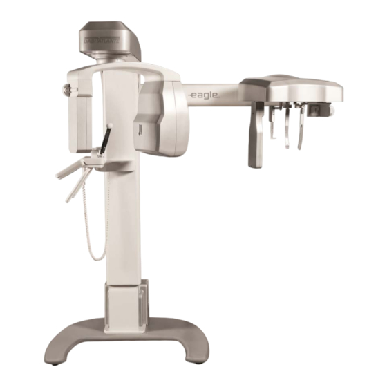
4.2. DIGITAL FIXED CONFIGURATION The following image shows the whole system. No optional ceph arm is available in this configuration. Moving Mechanism Rotating Arm X-Ray Tube Head SNAP-ON Sensor Head Support Control Panel Patient Handles Column Base (optional) -
Page 14: Analog Configuration
4.3. ANALOG CONFIGURATION The following image shows the whole system with optional Ceph arm mounted. Moving Cephalostat Arm Mechanism Cephalostat (Optional) Rotating Arm X-Ray Tube Head Film Holder Film Holder Ear rods Head Support Nose Support Control Panel Patient Handles Column Base (optional) -
Page 15: Power Supply Unit Options
4.1. POWER SUPPLY UNIT OPTIONS The following image shows the Power Supply Unit options that can be used in all configurations. Standard* Slim *Order on request 4.2. FREE STANDING BASE (OPTIONAL) The following image shows the optional Free Standing Base. The equipment will be fixed to the base and wall by an authorized technician during installation. -
Page 16: List Of Accessories
4.3. LIST OF ACCESSORIES Bite Guide Silicon chin rest cover Chin rest for patient with teeth TMJ and Sinus nose support Chin rest for patient without teeth... - Page 17 Nose Support Carpus Support ALL PARTS, ACCESSORIES AND OPTIONS DESCRIBED IN THIS OWNER'S MANUAL ARE FOR EXCLUSIVE USE. USE OF ANY PARTS, ACCESSORIES OR MATERIAL NOT SPECIFIED OR PROVIDED IN THIS OWNER'S MANUAL IS USER'S ATTENTION FULL RESPONSIBILITY.
-
Page 18: Recommended Computer System Specifications
5. RECOMMENDED COMPUTER SYSTEM SPECIFICATIONS It is imperative that this computer system be dedicated for the EAGLE Panoramic X-Ray Machine. Table 1 – Recommended Computer Specifications Operating System Windows 7 Professional – 64-bit Windows 8 Professional Windows 8.1 Professional Windows 10 Professional Intel ®... - Page 19 2 - Make sure the network adapter is installed. If not, install the network card drive using the CD shipped with the equipment. 3 - After installation restart the computer. To configure the network card, follow the procedure: 1 - Go to Control Panel Network Internet and Network Connections 2 - Click the right mouse button on the connection DESKTOP Intel Gigabit CT, and visit the properties.
- Page 20 8 - Initially, this setting is disabled. Change the value to 9014 bytes and then click 9 - Go to Settings Power Management tab and uncheck all items. 10 – Select Internet Protocol TCP/IP Version Proprieties 11 – Define the IP address 192.168.5.10 and Subnet Mask 255.255.255.0...
-
Page 21: Software Installation
6.2. SOFTWARE INSTALLATION Insert the accompanying media and execute the Setup.exe. The following screen should be displayed. 1 – Select the language 2 - Press NEXT: 3 – Read carefully the EULA and if you agree select “ I accept the agreement” and press NEXT... - Page 22 4 – Click on the Checkbox if you want create a desktop icon and Press NEXT 5 - Press INSTALL to start the installation.
- Page 23 6- The software will install all required software, please wait until if finish. 7 - Press FINISH to close the setup.
- Page 24 8- After installation, access Windows Start Menu / All Programs / Dental Imaging Software/ Dental Imaging Software. The main software window should display as follows: A DIGITAL VERSION OF THE SOFTWARE USER MANUAL WILL BE AVAILABLE WITH TECHNICAL CHARACTERISTICS GUIDELINES ON THE SOFTWARE OPERATION. ATTENTION...
-
Page 25: Imaging Programs
7. IMAGING PROGRAMS The EAGLE Panoramic X-Ray Machine contains a set of profiles. 7.1. PANORAMIC PROFILES: There are eight panoramic profiles available: from P1 to P6, P17 and P23: Program Description Standard Panoramic: This exposure constant vertical magnification of the dental arch region,... - Page 26 Child Panoramic Exposure: This exposure has a 15% size reduction with respect to the standard panoramic profile. Bitewing Exposure: This exposure is a bitewing-like image profile from premolar and molar area including parts of maxilla, mandible and rami. Improved Orthogonally Bitewing: This exposure is the bitewing-like image profile optimized for the beam to be more orthogonal in respect to the dental arch.
-
Page 27: Cephalometric Profiles
7.2. CEPHALOMETRIC PROFILES: Digital Cephalometric profile: With this profile it is possible to execute the following digital images: PA: Posterior-Anterior AP: Anterior-Posterior 45º Degrees Lateral Carpal Low Dosage Digital Cephalometric profile: With this profile it is possible to execute a lateral ceph with a smaller exposure area resulting in a lower dose to the patient. -
Page 28: Control Panel
8. CONTROL PANEL 8.1. INTRODUCTION The equipment has a control panel with six buttons and an LCD display as follows: The LCD display is graphical and has important information of the current status of the machine to help the user operate the unit. The keys have multiple functionality depending on the current state of the machine. -
Page 29: Control Panel Keys
8.2. CONTROL PANEL KEYS The controls are shown and their functions on the main screen are shown below: Plus Key: Used to increase kV, select patient age (child and adult), size (small, medium and large) and radiography type (i.e. standard panoramic and low dosage). -
Page 30: Control Panel Indicating Lights
8.3. CONTROL PANEL INDICATING LIGHTS Exposure-Signaling LED: The LED at the center of the symbol will light up during x-ray exposure. An audible warning will also sound. 8.4. REMOTE EXPOSURE SWITCH (OPTIONAL) A remote exposure switch installed outside of the radiation exposure room is available upon request or as required by state or country. -
Page 31: Turning The Equipment On
8.5. TURNING THE EQUIPMENT ON THE UNIT IS CONFIGURED FOR A LINE VOLTAGE DURING INSTALLATION BY THE TECHNICIAN ONLY. THIS IS A TECHNICAL PROCEDURE AND CANNOT BE DONE BY THE USER. ATTENTION BEFORE TURNING ON THE UNIT MAKE SURE THE UNIT IS CONNECTED TO THE CORRECT VOLTAGE. -
Page 32: Main Screen
8.6. MAIN SCREEN The main screen is shown below. To switch between functions use the SELECT key. Notice that only one item on the screen is selected each time. In the case shown below, the size is selected. INFO → LINE ADULT / →... - Page 33 FUNCTION DESCRIPTION DISPLAY INFORMATION AND EXPLANATION INFO LINE Displays current status of the machine. Equipment is not ready to expose x- rays. If exposure switch is pressed the equipment will operate in demonstration mode (no x-ray exposure). Equipment is ready to expose x-rays. Equipment is cooling down.
- Page 34 Medium patient selected Large patient selected This function is used to fine tune the kV after selecting the patient age and size or to directly select the kV. No kV selected: Demonstration mode. The range of kV is from 60kV to 85kV in increments of 2.5kV.
- Page 35 towards front of dental arch. PROFILE The image and text indicate the SELECTION selected profile. Example with standard panoramic selected.
-
Page 36: Preparing For The Exposure
9. PREPARING FOR THE EXPOSURE This section describes operations required for exposing images. The type of radiography depends on machine type and the media (sensor snap or sensor fixed) position. This section describes the steps required before positioning the patient on the machine. 9.1. - Page 37 To use it, follow the procedure below. Pass the first strap loop inside the sensor handle. Pass the second strap loop inside the first one. Pull the strap until the sensor is tightly secured.
- Page 38 Insert your hand into the strap loop. Adjust the safety strap to your wrist. THE SENSOR IS FRAGILE. WHILE REMOVING, HANDLING OR INSERTING SENSOR HOLD TIGHTLY WITH APPROPRIATE CARE. WARRANTY WILL BE VOIDED IF THE SENSOR IS DROPPED. ATTENTION...
- Page 39 In order to remove the SNAP-ON Sensor from the Holder (cephalostat or C-arm) proceed as indicated in the instructions below. 2. Rotate the knob 180 degrees until you 1. Hold the sensor tightly with your left hand release the sensor. and push the locking button with your right hand.
- Page 40 In order to insert the sensor follow the steps below. 2. Rotate the knob 180 degrees until you 1. Insert the sensor carefully. lock the sensor 3. Hold the sensor tightly with your left hand and push the locking button with your right hand...
-
Page 41: Digital Fixed Sensor Configuration
9.2. DIGITAL FIXED SENSOR CONFIGURATION CHANGING FOR PANORAMIC OR CEPHALOMETRIC MODE In order to change from Panoramic to Cephalometric mode, pull the locking button close to the panoramic sensor in C-arm. The equipment will automatically change the configuration to Cephalometric mode. In order to change from Cephalometric to Panoramic mode, push the locking button close to the panoramic sensor in C-arm. -
Page 42: Before Positioning The Patient
9.3. BEFORE POSITIONING THE PATIENT Ask the patient to remove any glasses, hearing aids, dentures, and personal jewelry such as earrings, necklaces, and hairpins. If required, place a protective lead apron over the patient’s body. Always follow local regulation. 9.4. GETTING THE SOFTWARE READY Open the Imaging software and press New Exposure. -
Page 43: Panoramic Exposures
10. PANORAMIC EXPOSURES This section uses operation concepts described on previous sections. Please refer to those sections when needed. This procedure will produce a full size panoramic exposure. If the child program is selected, the width and height of the exposed area will be slightly reduced. For this procedure it is necessary to use a chin rest. -
Page 44: Getting The Software Ready
Before positioning the patient, completely open the head support. Select the required panoramic profile (from P1 to P23). Select the correct exposure parameters in accordance with the patient characteristics. The table below gives the suggested parameters. Please use these values as a reference only. - Page 45 For a patient without teeth use the specific chin rest that doesn´t have a bite guide. Ask patient to lean his/her chin against it. Press the laser key to operate the patient positioning laser lights in order to assist with proper patient positioning. The laser diodes will automatically switch off after a period of time, or if the exposure button has been pressed.
-
Page 46: Taking A Panoramic Exposure
10.3. TAKING A PANORAMIC EXPOSURE When "Ready to Expose" is shown on the display the system is ready to take an exposure. Ask the patient to close their lips on the bite guide, swallow, place their tongue flat against the roof of their mouth, breathe normally, and stand as still as possible. Move to a protected area without losing direct eye contact to the patient. - Page 47 FOR TMJ TMJ PROFILE, P2, IS A DOUBLE EXPOSURE. AFTER THE FIRST EXPOSURE, POSITION THE PATIENT WITH OPEN MOUTH AND PROFILE (P2) PROCEED WITH THE SECOND EXPOSURE. ONLY The machine will enter a cool down process to setup for the next exposure. The display will indicate the status of the machine.
-
Page 48: Cephalometric Exposure
11. CEPHALOMETRIC EXPOSURE This section will occasionally use procedures described in previous sections. Please refer to those sections when needed. This procedure will produce a cephalometric exposure as selected: Waters PA Lateral Basal-Hirtz axial 45 degrees Carpal BEFORE START, OPEN THE HEAD POSITIONER AND REMOVE THE CHIN REST AND BITE GUIDE FROM THE PATIENT SUPPORT. -
Page 49: Positioning The Patient
11.2. POSITIONING THE PATIENT Guide the patient to the unit in front of the ceph arm rest. Adjust the height of the unit using the UP and DOWN keys on the control panel or ceph head as necessary. Ask the patient to step forward and hold still while you prepare the ceph head. Rotate the ceph head into the desired position (PA,AP, WATERS PA, CARPAL, BASAL-HIRTZ AXIAL, LATERAL OR 45 DEGREE). - Page 50 The machine will enter a cool down process to setup for the next exposure. The display will indicate the status of the machine. Cool down time will vary based on the type of exposure taken last. For digital machines you may save the image as required using the File/Save menu in the software.
-
Page 51: Procedures For Reuse
PROCEDURES FOR REUSE 12.1. CLEANING Using a clean moist cloth product, clean the equipment’s surface such as the head positioner, patient handles, nose support, silicon chin rest cover, chin rest, ear rods, temple stabilizers on a regular basis. It is recommended to use a moist cloth product with the following chemical properties: corrosion inhibitor, humectant effect, flotator;... -
Page 52: Troubleshooting Guide
13. TROUBLESHOOTING GUIDE 13.1. UNIT OPERATION PROBLEM Symptom Possible Cause Action required Wait for mains voltage to be Mains voltage not available available. Power supply cable is unplugged from back of Plug it into the equipment equipment Power supply cable is Equipment does not turn on Plug it into the wall socket unplugged from wall socket... -
Page 53: Patient Positioning Problem
13.2. PATIENT POSITIONING PROBLEM The standard panoramic image is showed below. A error in the patient positioning may generate several failures in the image. Symptom Possible Cause Action required Head tilted patient. teeth appear more Check the position of the Patient position to tune in amplified on one side and sagittal plane of the patient... - Page 54 Symptom Possible Cause Action required The patient's head rotated. teeth appear more Check the position of the Patient position for posterior amplified on one side and sagittal plane of the patient teeth in relation to the focal narrower on the other. with the laser line plane Head turned to the right...
- Page 55 Symptom Possible Cause Action required Adjust the focal plane of the Incisors and canines wide Position of the arch is equipment by positioning posterior of the focal plane. the Canine red laser on the and unsharp. tooth Canine tooth. Symptom Possible Cause Action required A row of teeth is bent...
- Page 56 Symptom Possible Cause Action required Reposition patient A row of flat teeth. Unable relying on the Frankfurt to see the roots of the upper Patient's head is tilted back plane laser teeth. Symptom Possible Cause Action required Ask the patient to take a step forward and stretch your Patient neck is not stretched Central area of the image is...
- Page 57 Symptom Possible Cause Action required Anterior teeth behind the Adjust the focal plane by focal plane Incisors and canines teeth positioning the Canine red blurred. Anterior teeth ahead of the laser on Canine tooth. focal plane Anterior teeth behind the focal plane Anterior teeth ahead of the focal plane Symptom Possible Cause...
- Page 58 Symptom Possible Cause Action required Reverse the patient's hands The patient's shoulders touch Patient is too large for the on the patient handles: Left the X-ray head or digital unit on the right side and vice- sensor / cassette holder. versa Check the positioning of the The inclination of the...
-
Page 59: Disposal Of The Unit
14.1. ENVIRONMENTAL CONTAMINATION In order to prevent environmental contamination or improper disposal of the EAGLE Panoramic X-Ray Machine, the equipment must be disposed of (according to local, state, or federal regulations) at an appropriate site. The equipment contains materials and solutions listed below which, upon completion of its useful life, must be disposed of at the appropriate sites. -
Page 60: Equipment Installation, Corrective Maintenance And Calibration
Atlante be liable to you or any other third party for any direct, indirect, punitive, incidental, consequential or special damages or lost profits arising from, relating to or connected with, the installation of or repair of a Dabi Atlante product by someone other than an our authorized service network. -
Page 61: Calibration
15.5. NETWORK OF AUTHORIZED SERVICE TECHNICIANS The installation and all services performed on DABI ATLANTE equipment/products should be done by technicians authorized by DABI ATLANTE, otherwise, warranty will be voided. To request electrical schematics, or component specifications not found in this manual, call the authorized service network DABI ATLANTE. -
Page 62: General Information
Model EAGLE Equipment classification according to FDA Classification class (risk class) CLASS II Equipment classification according to standard NBR IEC 60601-1 Protection against electric shock “Type-B” applied parts“ CLASS I (NBR IEC 60601-1) Protection against harmful water Ordinary equipment - IPX0... -
Page 63: X-Ray Generator
Intermittent The X-Ray Generator is mounted by the manufacturer. X-Ray machine with radiologic protection according to NBR IEC 60601-1-3:2001. X-Ray generator EAGLE NBR IEC 60601-2-7:1998 X-Radiation-emitting set EAGLE NBR IEC 60601-2-28:2001 Radiological equipment associated EAGLE NBRIEC60601-2-32:2001 16.5. TESTED EQUIPMENT LAW NORM... - Page 64 Amendment 1 EN 60601-1 (1992); Amendment 2 EN 60601-1 (1995); Amendment13 EN 60601-1 (1995); UL 60601- 60601-1-4-2004 EN 60601-1-3 (2001); EN 60601-2-7 (2001); EN 60601-2-28 (2001); EN 60601-2-32 (2001); IEC 60601-1; Emenda 1 IEC 601-1; IEC 60601-1-2; CISPR 11, edição 3.1 (1999); IEC 61000-4-2 (1999);...
-
Page 68: Irradiated Field Size - Digital Panoramic Exam (Pan: Adult And Child - Tmj - Maxillary Sinus)
16.6. IRRADIATED FIELD SIZE - DIGITAL PANORAMIC EXAM (PAN: ADULT AND CHILD – TMJ – MAXILLARY SINUS) 16.7. IRRADIATED FIELD SIZE – DIGITAL CEPH EXAM:... -
Page 69: Tube Specifications
ELECTROMAGNETIC EMISSIONS Manufacturer’s guidelines and declaration - electromagnetic emissions The EAGLE Panoramic X-Ray Machine has been designed for use in electromagnetic environments, according to the specifications below. The client or X-Ray Machine operator must ensure that the equipment is used in such type of environment. -
Page 70: Electromagnetic Immunity
16.10. ELECTROMAGNETIC IMMUNITY Manufacturer’s guidelines and declaration - electromagnetic immunity The EAGLE Panoramic X-Ray Machine has been designed for use in electromagnetic environments, according to the specifications below. The client or X-Ray Machine operator must ensure that the equipment is used in such type of environment. - Page 71 In order to evaluate the electromagnetic environment due to fixed RF transmitters, an electromagnetic inspection of the site is recommended. If the measurement of the field intensity on the site where the EAGLE Panoramic X-Ray Machine is used exceeds the applicable RF compliance level described...
- Page 72 EAGLE Panoramic X-Ray Machine The EAGLE Panoramic X-Ray Machine has been designed for use in electromagnetic environments where RF radiated perturbations are controlled. The client or user of the EAGLE Panoramic X-Ray Machine can help prevent electromagnetic interference by keeping a...
-
Page 73: Characteristic Cooling Of The X-Ray Generator
TO ENSURE SAFE OPERATION, THE OPERATOR MUST TURN AWAY FROM EQUIPMENT FOR SAFETY TO AVOID COLLISION WITH MOVING PARTS. THE PATIENT SHOULD INFORMED MOVEMENTS THAT EQUIPMENT WILL PERFORM. THE PATIENT SHOULD ALSO BE TOLD NOT TO MOVE DURING THE EXPOSURE. IT IS THE WARNING RESPONSIBILITY OF THE OPERATOR TO WATCH THE PATIENT AND INTERRUPT THE EXPOSURE IN SUCH... -
Page 74: Characteristic Curves Of The X-Ray Tube
16.12. CHARACTERISTIC CURVES OF THE X-RAY TUBE. Exposition Time... -
Page 75: Labels Of Identification
17. LABELS OF IDENTIFICATION 17.1. PACKAGE... -
Page 76: Product
17.2. PRODUCT... -
Page 77: Equipment Dimensions
18. EQUIPMENT DIMENSIONS... -
Page 78: Warranty
- Improper storage; - Action of nature agents; - Installation and service performed by persons not authorized by Dabi Atlante; - Damage to the painted parts and plastic painted or not, caused by misuse; The warranty period is 1 (one) years from the date of installation, provided that the equipment has not been stored for more than 1 (one) years from the date of issue of the invoice customer billing, first owner, until the date of installation.
Need help?
Do you have a question about the EAGLE and is the answer not in the manual?
Questions and answers