
Related Manuals for Electrolux Professional thermaline M L EO/DAO Series


Summary of Contents for Electrolux Professional thermaline M L EO/DAO Series
- Page 1 Electric Solid Top Eco top Installation and operating manual * 599A0UZ00 - 82.8120.01- 2021.06 *Original instructions...
- Page 2 Foreword Read the following instructions, including the warranty terms before installing and using the machine. Visit our website www.electroluxprofessional.com and open the Support section to: Register your product Get hints & tips of your product, service and repair information The installation, use and maintenance manual (hereinafter Manual) provides the user with information necessary for correct and safe use of the machine (or “appliance“).
-
Page 3: Table Of Contents
Contents A WARNING AND SAFETY INFORMATION....................5 General information ........................5 Personal protection equipment ......................6 General safety ..........................6 General safety rules ........................7 Safety signs to be placed near the machine area ................. 8 Transport, handling and storage ...................... 9 Installation and assembly ....................... - Page 4 OPERATING INSTRUCTIONS ....................... 30 Use ............................30 Features ........................... 31 Glass display ..........................31 Steel display..........................31 Main switch (optional) ........................31 First use ........................... 31 Heating control........................... 31 Switching on-off ......................... 31 Stand-by mode .......................... 31 I.10 Handrail (optional) ........................32 CLEANING ............................
-
Page 5: Awarning And Safety Information
WARNING AND SAFETY INFORMATION General information To ensure safe use of the machine and a proper understanding of the manual it is necessary to be familiar with the terms and typographical conventions used in the documentation. The following symbols are used in the manual to indicate and identify the various types of hazards: WARNING Danger for the health and safety of operators. -
Page 6: Personal Protection Equipment
Personal protection equipment Summary table of the Personal Protection Equipment (PPE) to be used during the various stages of the machine's service life. Stage Protective Safety Gloves Glasses Safety garments footwear helmet ● ○ ○ — — Transport ● ● —... -
Page 7: General Safety Rules
• Do not use products (even if diluted) containing chlorine (sodium hypochlorite, hydrochloric or muriatic acid, etc.) to clean the appliance or the floor under it. • Do not use metal tools to clean steel parts (wire brushes or Scotch Brite type scouring pads). -
Page 8: Safety Signs To Be Placed Near The Machine Area
– well lit. For the Customer's complete information, the residual risks remaining on the machine are indicated below: such situations are deemed improper and therefore strictly forbidden. Residual risk Description of hazardous situation Slipping or falling The operator can slip due to water or dirt on the floor Burns/abrasions (e.g. -
Page 9: Transport, Handling And Storage
Danger Meaning caution, hot surface danger of electrocution (shown on electrical parts with indication of voltage) End of use • When the appliance is no longer to be used, make it unusable by removing the mains power supply wiring. Transport, handling and storage •... -
Page 10: Machine Space Limits
• Verify that a safety circuit breaker is installed between the power cable of the appliance and the mains electric line. The contact opening max. distance and leakage current must comply with the local safety regulations. • Be sure to power the equipment with systems that are protected against overvoltage; the manufacturer declines all responsibility for effects due to anomalies induced by the electrical supply system. -
Page 11: Additional Safety Information
Preventive maintenance • In order to ensure the safety and performance of your equipment, it is recommended that service is undertaken by Electrolux Professional authorised engineers every 12 months, in accordance with Electrolux Professional Service Manuals. Please contact your local Electrolux Professional Service Centre for further details. -
Page 12: Machine Disposal
(current/voltage/frequency, including spikes and/ subject to local terms and conditions. or outages); Check on Electrolux Professional website the list of authorized – inadequate or interrupted water supply, steam, air, gas customer care. (including impurities and/or other that does not comply with the technical requirements for each machine);... -
Page 13: Appliance And Manufacturer's Identification Data
See the data plate located in the lower right corner to identify the appliance (see fig. below). Electrolux Professional AG - Allmendstrasse 28, CH - 6210 Sursee MW freq IMPORTANT When installing the appliance, make sure the electrical connection is carried out in compliance with that specified on the data plate. -
Page 14: How To Interpret The Factory Description
How to interpret the factory description 4 - Zones (cont'd.) The factory description on the data plate has the following 2 zones, base H3 meaning: 2 zones with Ecotop coating, base H3 4 zones, base H3 4 zones with Ecotop coating, base H3 5 - Module type (height) 250 mm, glass front panel 250 mm, steel front panel... -
Page 15: Copyright
Disposal of packing Manufacturer Electrolux Professional SpA or any other The packing must be disposed of in compliance with the service centre authorised by Electrolux current regulations in the country where the appliance is used. -
Page 16: Characteristics Of Personnel Enabled To Operate On The Machine
D.10 Characteristics of personnel enabled to • adequate general basic education and technical knowledge for reading and understanding the contents of the manual, operate on the machine including correct interpretation of the drawings, signs and The Customer is responsible for ensuring that persons pictograms;... - Page 17 Floor installation options: 3. Against the wall on steel plinth or 1. On steel plinth or adjustable feet 2. On concrete plinth adjustable feet 800 / 850 / 900 800 / 850 / 900 800 / 850 / 900 660 / 710 / 760 660 / 710 / 760 730 / 780 / 840 4.
-
Page 18: Installation And Connection Diagram
Installation and connection diagram EI = Electrical connection EQ = Potential equalisation (x)* = Protective panel 1000... - Page 19 Wall mounted appliances drilling: ø18, depth 145mm 1 0 0 1 0 0 1 3 0 2 2 2 EI = Electrical connection EQ = Potential equalisation (x)* = Protective panel 1000...
- Page 20 Solid top on open base +100/+200 1 5 0 1 3 0 +100/+200 EI = Electrical connection EQ = Potential equalisation (x)* = Protective panel 1000...
- Page 21 Solid top on warming cabinet +100/ +200 +100/ +200 EI = Electrical connection EQ = Potential equalisation (x)* = Protective panel 1000...
- Page 22 Solid top on oven +100/+200 +100/ +200 EI = Electrical connection EQ = Potential equalisation (x)* = Protective panel 1000...
-
Page 23: Accessing The Appliance's Internal Components
Accessing the appliance’s internal components Access to the main power supply INSTALLATION AND ASSEMBLY Appliance type Installation options: 1. Wall mounted (not available for all appliances) 2. Standing against the wall • on adjustable feet • on steel plinth • on concrete plinth 3. -
Page 24: Distances / Walls
Distances / walls Before installation The appliance must not be installed on flammable walls. If an Depending on your model, prepare the following before the appliance is set up next to or against temperature-sensitive appliance is installed and positioned correctly: furniture or similar, keep a safety-distance of approximately 50 •... -
Page 25: Securing Or Adjusting To The Floor (Optional)
3. Shift the appliance onto the transport pallet such that all of the installation connections lie within the appliance. 4. Tip the appliance until it is standing on the floor. Then lift at the front and remove the transport pallet. 5. -
Page 26: Positioning
G.5.3 Positioning We recommend using a lifting truck with a stable shelf to take the unit down from the transport pallet and position it into place. Lifting the unit onto the hand truck has to be done by hand, with two or more men required depending on the unit size. 1. -
Page 27: Side Panels And Base Models
Using a solid tool, break nuts C from connecting rail D. Seal the whole length of the joint with long lasting Insert connecting rail D into the gap between the top, silicone. Attach the rail D using the supplied screws making sure marking E is pointing forwards. -
Page 28: Fixing The Side Panels
Fixing the side panels G.8.1 Panels with a 12,5 mm overhang Attach connecting rails B and C with the supplied Bring the side panel D into position. screws A. Make sure marking on part B on the rail is Put the 5 hooks of the panel F into the slots E. pointing forwards. -
Page 29: Side Cover Without Overhang
G.8.2 Side cover without overhang The side cover should only be used as a closing off against the wall, against a niche and in between appliances (provided that these have the same dimensions). Standard cover has pre-cuts that you can adapt to the appliances according to the left/right side. Fit the 4 cage nuts A into the dedicated slots on the Attach connecting rails C and D with the supplied frame. -
Page 30: Helectrical Installation
ELECTRICAL INSTALLATION Gas, electricity, water and other The Installation and Connection Diagram (F Installation DIAGRAMS) shows the position of the main terminal board. connections (if present, depending on To get access to the connection terminal inside the appliance, the appliance and/or model) follow the instructions in F.3 Accessing the appliance’s internal •... -
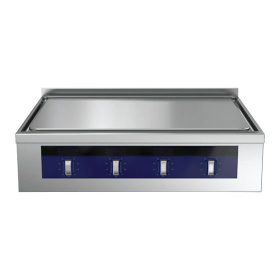
Page 31: Features
IMPORTANT Features Models with Eco top coating: before first use, run all cooking zones at maximum power for at least one hour, without cookware, in order to harden the coating. Heating control 1. Splashback (optional) 2. Cooking surface 3. Controls 4. -
Page 32: Handrail (Optional)
I.10 Handrail (optional) For prolonged downtimes, switch off the appliance to avoid unnecessary energy consumption. For correct assembly/disassembly of the handrail, refer to the dedicated installation instructions. WARNING CAUTION The appliance's heat surfaces If the handrail is present, do not place on it and cooking pan can be very hot more than 25 kg per meter of structure. -
Page 33: Gaps And Joints
• You can remove oxidised spots with glass-content sand- 2. Carefully lift the collecting tray out of its fixation. Use both paper (no metal-content sandpaper). hands to keep it in an horizontal position. • Finally, oil the entire cooking area with a thin layer of cooking oil and turn on the appliance to its minimum power level until the oil is completely evaporated/absorbed. -
Page 34: Air Filter (Optional)
J.12 Air filter (optional) If present, remove the air filter at least once a month from under the lower front panel and clean with water and detergent used for manual dishes cleaning. IMPORTANT Non-compliance with the above instruction will result in filter inefficiency and may lead to malfunc- tioning of the appliance. -
Page 35: Ltroubleshooting
Should none of the measures listed below resolve the fault or if an error occurs that is not described here, disconnect the appliance from the mains supply (gas, water, electricity) and immediately contact the Electrolux Professional Customer Care Service. What to do if... - Page 38 Electrolux Professional AG Allmendstrasse 28 CH - 6210 Sursee www.electroluxprofessional.com...
Need help?
Do you have a question about the thermaline M L EO/DAO Series and is the answer not in the manual?
Questions and answers