Table of Contents
Advertisement
Quick Links
PD4-6624 & PD4-6628 Loop-Powered Flow Rate/Totalizers
Instruction Manual
•
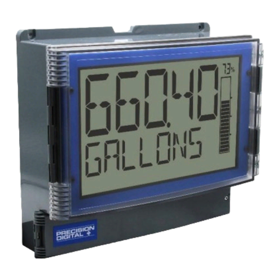
Large Display NEMA 4X, IP65 Loop-Powered Wall & Pipe Mounted Flow Rate/Totalizers
•
4-20 mA Input Displayed with ±0.02% Accuracy
•
2.1 Volt Drop Maximum
•
2.8" (71 mm) 5 Alphanumeric 14-Segment Characters Top Display
•
1.5" (39 mm) 8 Alphanumeric 14-Segment Characters Bottom Display
•
20-Segment Bargraph with Numeric Percent Indication
•
8-Digit Total & Grand Total Display, Up to 13 Digits Using Both Lines
•
Display Rate & Total Simultaneously
•
Automatic or Manual Batch Control
•
Display Open Channel Flow with Programmable Exponent Feature
•
32-Point Linearization & Square Root Extraction
•
(2) Open Collector Outputs Standard; Assignable to Pulse, Alarm, Timer, or Stopwatch
•
(2) Optional Loop-Powered Solid-State Relays; Assignable to Alarm, Sample, Timer, Batch, or Stopwatch
•
Stopwatch & Timer Functions to Drive Relays & Open Collectors
•
Optional Isolated 4-20 mA Analog Output
•
Display Relay Runtime & Cycle Count via Relay Info Menu
•
Free PC-Based MeterView XL USB Programming Software
•
®
HART
Protocol Transparent
•
Externally DC Powered Backlight with Red Backlight for Alarm Conditions
•
Safe Area Operating Temperature Range: -40 to 75°C (-40 to 167°F)
•
Conformal Coated PCBs for Dust & Humidity Protection
•
Password Protection
•
ATEX and IECEx Certified as Intrinsically Safe (PD4-6628 Only)
•
Pipe Mounting Kit Available
•
Light / Horn & Reset Button Accessory
•
Control Station Accessory for Remote Operation of Instrument
•
3-Year Warranty
PRECISION DIGITAL CORPORATION
233 South Street • Hopkinton MA 01748 USA
Tel (800) 343-1001 • Fax (508) 655-8990
www.predig.com
All Models
PD4-6628 Only
IECEx
Advertisement
Table of Contents

Subscribe to Our Youtube Channel
Related Manuals for Precision Digital Corporation Loop Leader+ Series


Summary of Contents for Precision Digital Corporation Loop Leader+ Series
- Page 1 Pipe Mounting Kit Available • Light / Horn & Reset Button Accessory • Control Station Accessory for Remote Operation of Instrument • 3-Year Warranty PRECISION DIGITAL CORPORATION 233 South Street • Hopkinton MA 01748 USA Tel (800) 343-1001 • Fax (508) 655-8990 www.predig.com...
- Page 2 PD4-6624 & PD4-6628 Loop-Powered Flow Rate/Totalizers Instruction Manual The Complete PD4-6600 Series General Purpose PD4-6603 PD4-6604 PD4-6624 Feet & Inches Meter Process Meter Flow Rate/Totalizer Hazardous Area PD4-6607 PD4-6608 PD4-6628 Feet & Inches Meter Process Meter Flow Rate/Totalizer...
-
Page 3: Table Of Contents
PD4-6624 & PD4-6628 Loop-Powered Flow Rate/Totalizers Instruction Manual Table of Contents Introduction ......................6 Key Features ....................... 7 Ordering Information ..................11 Accessories ....................11 Specifications ....................14 Display ......................14 General ......................14 Input ......................15 Rate/Totalizer ....................15 Batch Control .................... - Page 4 PD4-6624 & PD4-6628 Loop-Powered Flow Rate/Totalizers Instruction Manual Setting the Display Features (DISPLAY) ............ 38 Changing the Engineering Units (UNITS) ..........38 Changing the Decimal Point (DEC. P T) ............38 Enabling or Disabling the Commas on the Bottom Display (COMMA) ..39 Display Capabilities Optimization (TOP and BOTTOM)........
- Page 5 PD4-6624 & PD4-6628 Loop-Powered Flow Rate/Totalizers Instruction Manual Table of Figures Figure 1. Meter Mounting Holes Location ............20 Figure 2. Meter Mounting Holes Dimensions ............. 20 Figure 3. Meter Dimensions – Side View ............20 Figure 4. Meter Dimensions - Front View ............20 Figure 5.
-
Page 6: Introduction
Limited Warranty sunlight or dimly lit areas. The PD4-6628 model is an intrinsically safe and nonincendive version of the Loop Precision Digital Corporation warrants this Leader+ that is agency approved for installation in product against defects in material or hazardous areas. It also carries electrical safety workmanship for the specified period under “Specifications”... -
Page 7: Key Features
Instruction Manual PD4-6624 & PD4-6628 Loop-Powered Flow Rate/Totalizers Key Features 1. Available on PD4-6624 only. Requires external 24 VDC power. 2. Backlight requires external 24 VDC power. Large Informative Display Commas on 8-Digit Totalizer for Easy Reading One of the most convenient features of the PD4 Loop Leader+ Series is its large, dual-line display. - Page 8 PD4-6624 & PD4-6628 Loop-Powered Flow Rate/Totalizers Instruction Manual Predefined and Custom Units Input Signal Conditioning Functions (FUNCTION) The PD4-6624/28 flow rate/totalizers have the most common predefined rate and volume units. If the The Function menu is used to select the input signal desired unit is not available, the user can program a conditioner applied to the input: linear, square root, custom unit.
- Page 9 PD4-6624 & PD4-6628 Loop-Powered Flow Rate/Totalizers Instruction Manual Total Stored in Non-Volatile Rate/Totalizer Features Memory Display Flow Rate & Total at the Total and grand total values, and all programmed Same Time settings are stored in non-volatile memory for a The PD4-6624 can display flow rate and total at the minimum of ten years if power is lost.
- Page 10 PD4-6624 & PD4-6628 Loop-Powered Flow Rate/Totalizers Instruction Manual Total Reset via Digital Input Batch Control Capabilities The PD4-6624’s digital input may also be used to reset the total or grand total using a PDA2361-R control station. The meter can be equipped with two solid-state relays that may be set up for batch control.
-
Page 11: Ordering Information
Instruction Manual PD4-6624 & PD4-6628 Loop-Powered Flow Rate/Totalizers Ordering Information PDA2360 Plastic Control Stations General Purpose Instruments Loop Leader+ PD4-6624 • General Purpose Model Description PD4-6624–LNN Large Display Loop-Powered Rate/Totalizer, General Purpose, No Options PD4-6624–L5N Large Display Loop-Powered Rate/Totalizer, General Purpose, Two Solid-State Relays and Model Description... - Page 12 PD4-6624 & PD4-6628 Loop-Powered Flow Rate/Totalizers Instruction Manual Light / Horn & Button Accessories Pipe Mounting Kit PD4-6624 Meter Shown mounted to pipe using PD4-6624 meter shown with MOD-PD2LHRB1 Red Light / PDA6260 pipe mounting kit. See Pipe Mounting Horn and Button. Meter sold separately. Instructions on page 21 for details.
- Page 13 PD4-6624 & PD4-6628 Loop-Powered Flow Rate/Totalizers Instruction Manual PDA1024-01 24 VDC Power Supply Useful Tools PD9501 Multi-Function Calibrator The PDA1024-01 is a DIN rail mounted 1.5 A, 24 VDC power supply that can be used to power the 4-20 mA transmitter. This PD9501 Multi-Function Calibrator has a variety...
-
Page 14: Specifications
Instruction Manual PD4-6624 & PD4-6628 Loop-Powered Flow Rate/Totalizers Specifications General Except where noted all specifications apply to operation at +25°C. Programming Buttons behind lower panel door & Free Method PC-based USB programming software Display Enclosure & Material: High impact Polycarbonate with Materials UV stabilizer enclosure, UL 94V-0 Display... -
Page 15: Input
PD4-6624 & PD4-6628 Loop-Powered Flow Rate/Totalizers Instruction Manual Input Rate/Totalizer Input 4-20 mA Rate Display Top display: -9999 to 99999; Accuracy ±0.02% of span ±1 count, Bottom display: -9,999,999 to 99,999,999 Square root and (with commas) programmable exponent: 10-100% FS Total &... -
Page 16: Common Open Collector & Relay Specifications
PD4-6624 & PD4-6628 Loop-Powered Flow Rate/Totalizers Instruction Manual Common Open Collector & Solid-State Relays Relay Specifications Rating 250 VAC/VDC @ 1A resistive 75VA; 250VAC; 0.6A pilot duty Number Two open collectors & two relays (inductive) 25VA; 250VDC; 0.6A pilot duty High or Low User programmable for high or low alarm (inductive) -
Page 17: Remote Contacts
PD4-6624 & PD4-6628 Loop-Powered Flow Rate/Totalizers Instruction Manual General Compliance Remote Contacts Information Function Terminals provided for remote operation of all four programming / operation buttons (use PDA2364-MRUE control station). Electromagnetic Compatibility Remote Menu, Right, Up, Enter Buttons EMC Emissions • CFR 47 FCC Part 15 Subpart B Class A emissions requirements (USA) Remote... -
Page 18: Pd4-6628 Compliance Information
PD4-6624 & PD4-6628 Loop-Powered Flow Rate/Totalizers Instruction Manual PD4-6628 Compliance For European Community: The PD4-6628 must be installed in accordance with Information the ATEX directive 2014/34/EU, the product certificates CML 18ATEX2091X, IECEx CML Hazardous Area Approvals 18.0051X and the product manual. There is no need to remove the meter from its case to ATEX II 1 G D... -
Page 19: Eu Declaration Of Conformity
PD4-6624 & PD4-6628 Loop-Powered Flow Rate/Totalizers Instruction Manual EU Declaration of Conformity Installation For shipments to the EU and UK, a Declaration of There is no need to open the clear plastic front cover Conformity was printed and included with the product. in order to complete the installation, wiring, and setup For reference, a Declaration of Conformity is also of the meter. -
Page 20: Wall Mounting Instructions
PD4-6624 & PD4-6628 Loop-Powered Flow Rate/Totalizers Instruction Manual Mounting Dimensions Wall Mounting Instructions The meter can be mounted to any wall using the four provided mounting holes. Note that the bottom mounting holes are located underneath the lower door panel. To mount the meter to a wall, follow these instructions •... -
Page 21: Pipe Mounting Instructions
PD4-6624 & PD4-6628 Loop-Powered Flow Rate/Totalizers Instruction Manual Pipe Mounting Instructions The meter can also be mounted to a pipe using the optional pipe mounting kit (PDA6260). This kit includes two mounting plates, two U-bolts, and the necessary nuts and bolts. To mount the meter to a pipe using the pipe mounting kit accessory, follow these instructions. -
Page 22: Meterview Xl Programming Software
PD4-6624 & PD4-6628 Loop-Powered Flow Rate/Totalizers Instruction Manual 4. Double-click MeterView XL Windows Installer MeterView XL Programming Package file to open: Software Free, PC-based, MeterView XL software that connects to the meter via a USB cable is available for programming and setup of the meters. This software 5. -
Page 23: Connecting To The Computer
PD4-6624 & PD4-6628 Loop-Powered Flow Rate/Totalizers Instruction Manual 7. Choose the folder location where you would 10. Finally, the Installation Complete window will appear. Click “Close” to exit: like the software to be installed to and select options for use. Then click “Next” to continue: Now you are ready to open the MeterView XL software 8. -
Page 24: Connections
Instruction Manual PD4-6624 & PD4-6628 Loop-Powered Flow Rate/Totalizers Connections All connections are made to screw terminal connectors located behind the lower panel door. Remove the single securing screw in order to access the wiring terminals. This section is only intended for PD4-6624 safe area installations. •... -
Page 25: Wiring Diagrams
Instruction Manual PD4-6624 & PD4-6628 Loop-Powered Flow Rate/Totalizers Wiring Diagrams Safe Area Current Loop (4-20 mA) Connections Signal connections are made to a four-terminal • PD4-6628 installation must be performed in connector labeled INPUTS. See Connectors Labeling accordance with Control Drawing LIM4-6600-2 on page 24. -
Page 26: Safe Area 4-20 Ma Output Connections
PD4-6624 & PD4-6628 Loop-Powered Flow Rate/Totalizers Instruction Manual Safe Area 4-20 mA Output Remote Operation of Meter Connections The meter can be operated remotely by connecting a PDA2364-MRUE control station to the Remote Contacts Connections for the 4-20 mA transmitter output are located behind the lower panel door of the meter as made to the connector terminals labeled mA OUT. -
Page 27: Wiring Connections For Mod-Pd2Lh Models
Instruction Manual PD4-6624 & PD4-6628 Loop-Powered Flow Rate/Totalizers Wiring Connections for MOD-PD2LH Models The following diagram is for MOD-PD2LH models with a single color light. The Light / Horn cannot be powered by the 4-20 mA loop. To use the Light / Horn an external power supply must be used such as the PDA1024-01 as the following diagram illustrates. -
Page 28: Setup And Programming
PD4-6624 & PD4-6628 Loop-Powered Flow Rate/Totalizers Instruction Manual Setup and Programming The meter is factory calibrated prior to shipment to display 0.00 to 100.00, which corresponds to the 4-20 mA input. The calibration equipment is traceable to NIST standards. Overview There are no jumpers to set;... -
Page 29: Programming Buttons
Instruction Manual PD4-6624 & PD4-6628 Loop-Powered Flow Rate/Totalizers Programming Buttons Button Description Button Description Bargraph with Percentage Indication Menu Up Arrow/F2 Right Acknowledge Arrow/F1 (Enter)/F3 • Press the Menu button to enter or exit the Programming Mode at any time. •... -
Page 30: Display Functions & Messages
Instruction Manual PD4-6624 & PD4-6628 Loop-Powered Flow Rate/Totalizers Display Functions & Messages Parameter Action/Setting Description PULSE Program the open collector for The meter displays various functions and messages during pulse output setup, programming, and operation. The following table shows the main menu functions and messages in the order ALARM Program the open collector for they appear in the menu. - Page 31 PD4-6624 & PD4-6628 Loop-Powered Flow Rate/Totalizers Instruction Manual Parameter Action/Setting Description Parameter Action/Setting Description FUNCTION FILTER Select linear, square root, or Set noise filter value programmable exponent function 1. 0 SEC 1 second LINEAR Set meter for linear function and 2.
- Page 32 PD4-6624 & PD4-6628 Loop-Powered Flow Rate/Totalizers Instruction Manual Parameter Action/Setting Description Parameter Action/Setting Description TIMER R2 RST FN Relay 2 timer Set the function key or digital input to reset a value TIMER. F N Set the function key or digital input RESET to start or stop a timer Reset min, max, or max/min rate...
- Page 33 PD4-6624 & PD4-6628 Loop-Powered Flow Rate/Totalizers Instruction Manual Parameter Action/Setting Description Parameter Action/Setting Description Display the rate and the total’s RATE PCT RATE+TU Set the bargraph to display the rate percentage of full scale units alternating RATE RATE+U Set the bargraph to display the Display the rate and its units rate percentage of a user-selected alternating...
-
Page 34: Main Menu
Instruction Manual PD4-6624 & PD4-6628 Loop-Powered Flow Rate/Totalizers Main Menu The main menu consists of all the meter’s programmable functions: Input, Output, Advanced, and Display. • Press Menu button to enter Programming Mode then press the Right-Arrow button to move forward through the menu and the Up-Arrow button to move back. -
Page 35: Setting Numeric Values
PD4-6624 & PD4-6628 Loop-Powered Flow Rate/Totalizers Instruction Manual Setting Numeric Values The numeric values are set using the Right and Up-Arrow buttons. Press Right-Arrow to select next digit and Up-Arrow to increment digit value. The selected digit will flash. Press and hold Up-Arrow to auto-increment the display value. If you have made a mistake or would like to enter a new value, select the left-most digit and press and hold the Right-Arrow button until all digits reset to zero. -
Page 36: Scaling The 4-20 Ma Input (Input)
PD4-6624 & PD4-6628 Loop-Powered Flow Rate/Totalizers Instruction Manual Scaling the 4-20 mA Input (INPUT) It is very important to read the following information before proceeding to program the meter: • The meter is factory calibrated prior to shipment to display 0.00 to 100.00 gal/s, which corresponds to the 4-20 mA input. -
Page 37: Available Engineering Units
Instruction Manual PD4-6624 & PD4-6628 Loop-Powered Flow Rate/Totalizers Available Engineering Units Rate Units (RATE) The meter has preprogrammed rate and time base GAL/(T) Gallons per time unit (T) units. The following are the available units to choose L/(T) Liters per time unit (T) from: IGAL/(T) Imperial gallons per time unit (T) -
Page 38: Scaling Example
Instruction Manual PD4-6624 & PD4-6628 Loop-Powered Flow Rate/Totalizers Scaling Example The 4-20 mA input can be scaled to the appropriate values for a given application. The 4 mA input (input 1) should have a corresponding display value (display 1) which represents the low end of the process value range being measured by the transmitter. -
Page 39: Enabling Or Disabling The Commas On The Bottom Display (Comma)
Instruction Manual PD4-6624 & PD4-6628 Loop-Powered Flow Rate/Totalizers Dual-Scale Mode: Enabling or Disabling the Commas on Top Display: Toggle Rate and GPM Units the Bottom Display (COMMA) Bottom Display: Toggle Rate and CFM Units The bottom display is set to show a comma separating the thousands and millions place by default if a numeric value is being displayed. -
Page 40: Configuring The Display (Top And Bottom)
PD4-6624 & PD4-6628 Loop-Powered Flow Rate/Totalizers Instruction Manual The bottom display (BOTTOM) can display: Configuring the Display • Total (with units or tag alternating) (TOp and BOTTOM) • Total, its units, and the rate units alternating The two display lines (Top and Bottom) can be •... -
Page 41: Programming The Outputs (Output)
PD4-6624 & PD4-6628 Loop-Powered Flow Rate/Totalizers Instruction Manual Programming the Outputs (OUTPUT) All models come with two open collectors. Depending on the model purchased, the meter may include two solid-state relays, and one 4-20 mA output. The Output menu will only show options for the available outputs. See Ordering Information on page 11 for details. -
Page 42: Open Collector Outputs (Open Collectr)
PD4-6624 & PD4-6628 Loop-Powered Flow Rate/Totalizers Instruction Manual Open Collector Outputs (OPEN COLLECTR) The meter is equipped with two NPN open collector outputs that may be set up for pulse outputs, alarms, timed pulses, total reset, or disabled. Pulse outputs can be set to transmit the rate, total, or grand total. Output 2 may be used to generate a quadrature output based on the other open collector output. - Page 43 PD4-6624 & PD4-6628 Loop-Powered Flow Rate/Totalizers Instruction Manual Pulse Output (PULSE) Pulse outputs may be assigned to output the rate, total, or grand total at a programmable factor. If the output is assigned to rate, the factor is a multiplier that determines the number of pulses generated based on the rate. For example, if the meter display shows 100 gallons/second and the factor is set to 2, the number of pulses generated per second would be 200.
- Page 44 PD4-6624 & PD4-6628 Loop-Powered Flow Rate/Totalizers Instruction Manual Alarm (ALARM) Alarm outputs may be assigned to the rate, total, grand total, or the digital input. When assigned to the rate, the alarm may be set as either a high alarm or a low alarm. Alarm actions (AUTO, AUTO. M AN, LATCH, L-CLEAR) determine how and when the alarm should be reset.
- Page 45 PD4-6624 & PD4-6628 Loop-Powered Flow Rate/Totalizers Instruction Manual Flashing Red Alarm (RED) The last two lines in the preceding menu flow chart show how to program the display to turn red, flash, and display a message when an alarm occurs. Alarm 1 is High Alarm: Alarm 2 is Low Alarm: Timer (TIMER)
- Page 46 PD4-6624 & PD4-6628 Loop-Powered Flow Rate/Totalizers Instruction Manual Stopwatch (STPWATCH) The stopwatch function may be used to manually run and control a process for a specific time interval up to 99 hrs, 59 min, and 59 seconds. The stopwatch function may be assigned to any open collector. There are three settings needed to use the function effectively.
-
Page 47: Solid-State Relay Outputs (Relay)
PD4-6624 & PD4-6628 Loop-Powered Flow Rate/Totalizers Instruction Manual Solid-State Relay Outputs (RELAY) The meter is optionally equipped with two solid-state relays that may be set up for alarms, sample, timer, batch control, or stopwatch. Alternatively, they may be disabled. Alarms are available based on the rate, total, grand total, or the digital input. The alarm status will show on the display even if the output is not wired. - Page 48 PD4-6624 & PD4-6628 Loop-Powered Flow Rate/Totalizers Instruction Manual Alarm (ALARM) Alarm outputs may be assigned to the rate, total, grand total, or the digital input. When assigned to the rate, the alarm may be set as either a high alarm or a low alarm. Alarm actions (AUTO, AUTO. M AN, LATCH, L-CLEAR) determine how and when the alarm should be reset.
- Page 49 PD4-6624 & PD4-6628 Loop-Powered Flow Rate/Totalizers Instruction Manual Sample (SAMPLE) A relay set to sample will trigger when the total or grand total value has incremented by a programmed amount. The relay can be programmed to stay on for a specified amount of time. For example: if a relay is set to sample the total with a COUNT of 1,000 and a TIME of 10 seconds, the relay will engage for 10 seconds whenever the total has incremented by 1,000 (e.g.
- Page 50 PD4-6624 & PD4-6628 Loop-Powered Flow Rate/Totalizers Instruction Manual Batch Control (BATCH) Selecting batch control for relay 1 enables the batching features on the meter. The top display is changed to show the total and the bottom display is changed to display the preset batch amount. The function keys are changed so that F1 starts a batch, F2 opens the preset menu to allow the preset value to be changed, and F3 stops the currently running batch.
- Page 51 PD4-6624 & PD4-6628 Loop-Powered Flow Rate/Totalizers Instruction Manual Batch Control Relay 2 The BATCH option only appears under relay 2 if relay 1 has also been set to batch control. The second relay may be programmed as a preclose relay or as another batching relay with its own preset amount. Flashes ENTER ENTER...
-
Page 52: Isolated 4-20 Ma Output (4-20 Ma)
PD4-6624 & PD4-6628 Loop-Powered Flow Rate/Totalizers Instruction Manual Isolated 4-20 mA Output (4-20 mA) The 4-20 mA menu is used to scale the 4-20 mA output based on display values. This menu is not present on models without a 4-20 mA output option. The 4-20 mA analog output (if equipped) can be scaled to provide a 4-20 mA signal for the rate or total display range or to simply retransmit the 4-20 mA input. -
Page 53: Advanced Features Menu (Advanced)
PD4-6624 & PD4-6628 Loop-Powered Flow Rate/Totalizers Instruction Manual Advanced Features Menu (ADVANCED) To simplify the setup process, functions not needed for most applications are located in the Advanced Features menu. The options under advanced features include advanced rate, total, and grand total setup, cutoff, filter, password, function key programming, and system settings. -
Page 54: Input Signal Conditioning Functions (Function)
PD4-6624 & PD4-6628 Loop-Powered Flow Rate/Totalizers Instruction Manual Input Signal Conditioning Functions (FUNCTION) The Function menu is used to select the input signal conditioner applied to the input: linear, square root, programmable exponent, or round horizontal tank volume calculation. Multi-point linearization is part of the linear function selection. Meters are set up at the factory for linear function with 2-point linearization. - Page 55 PD4-6624 & PD4-6628 Loop-Powered Flow Rate/Totalizers Instruction Manual Square Root Linearization (SQROOT) The square root function can be used to linearize the signal from a differential pressure transmitter and display flow rate in engineering units. PD4-6624 Displaying Flow Rate by Applying the Square Root Function to the Output of a DP Transmitter.
- Page 56 PD4-6624 & PD4-6628 Loop-Powered Flow Rate/Totalizers Instruction Manual Programmable Exponent Linearization (EXPONENT) The programmable exponent can be used to linearize the signal from level transmitters in open-channel flow applications using weirs and flumes. The PD4-6624, in combination with an ultrasonic level transmitter, makes for an economical way to measure and display open channel flow rate and total in most weirs and flumes.
- Page 57 PD4-6624 & PD4-6628 Loop-Powered Flow Rate/Totalizers Instruction Manual The Programmable Exponent function is programmed in the following manner: ENTER ENTER RATE 1. 5 000 RATE EXPONENT EXPONENT SCALE. C AL ENTER ENTER ENTER SCALE SCALE UNITS RATE UNITS RATE ENTER Rate Time Bases Rate Units...
- Page 58 PD4-6624 & PD4-6628 Loop-Powered Flow Rate/Totalizers Instruction Manual Multi-Point Linearization (LINEAR) Up to 32 linearization points can be selected for rate under the LINEAR function. Multi-point linearization can be used to linearize the input for non-linear signals to convert level to flow using weirs and flumes with complex equations. These points are established via direct entry (SCALE) or with a live calibration signal source (CAL).
- Page 59 PD4-6624 & PD4-6628 Loop-Powered Flow Rate/Totalizers Instruction Manual Advanced Total and Grand Total Setup (ADV TOTAL & ADV GTOTAL) The advanced total and grand total menu contain the count (COUNT) and reset (RESET) menus. The count menu allows the digit limit to be selected between 8-digit (bottom display only) and 13-digit (uses top and bottom display to display full number) and the initial value at which the total or grand total should start counting.
- Page 60 PD4-6624 & PD4-6628 Loop-Powered Flow Rate/Totalizers Instruction Manual Advanced Scaling and Calibration (SCALE. C AL) This menu offers options to scale or calibrate the meter. Scaling the Input (SCALE) The scale menu in the Advanced menu is the same as the scale menu in the Input menu. See Scaling the 4-20 mA Input (INPUT) on page 36 for details about scaling the meter.
-
Page 61: Additional Engineering Units
PD4-6624 & PD4-6628 Loop-Powered Flow Rate/Totalizers Instruction Manual Additional Engineering Units • If the total is disabled and the dual-scale level feature has been selected, the menus for PV1 & PV2 are enabled. • Additional engineering units become available as shown below. ENTER ENTER ENTER... -
Page 62: Low-Flow Cutoff (Cutoff)
PD4-6624 & PD4-6628 Loop-Powered Flow Rate/Totalizers Instruction Manual Low-Flow Cutoff (CUTOFF) The low-flow cutoff feature allows the meter to be programmed so that the often-unsteady output from a differential pressure transmitter at low flow rates always displays zero on the meter. The cutoff value may be programmed from 0.1 to 99999. -
Page 63: Programmable Function Keys User Menu (User)
PD4-6624 & PD4-6628 Loop-Powered Flow Rate/Totalizers Instruction Manual Making Changes to a Password Protected Meter If the Main password is enabled, the meter will display the message LOCKED when the Menu button is pressed. If the Total or Grand Total passwords are enabled, the meter will display the message LOCKED when trying to reset or change the total or grand total. - Page 64 Instruction Manual PD4-6624 & PD4-6628 Loop-Powered Flow Rate/Totalizers Function Keys & Digital Input Display Description SETPT. R 1 Available Settings Set relay 1 set point SETPT. R 2 Set relay 2 set point Refer to the following table for descriptions of each SWATCH.
-
Page 65: Changing System Settings (System)
PD4-6624 & PD4-6628 Loop-Powered Flow Rate/Totalizers Instruction Manual Enabling the Function Key Hint 4-20 mA Output Calibration Procedure Feature (HINT) 1. Go to the Advanced Features menu and navigate to the SYSTEM menu and press Enabling the function key hint feature will cause a hint Enter. - Page 66 PD4-6624 & PD4-6628 Loop-Powered Flow Rate/Totalizers Instruction Manual The Internal Calibration menu is part of the Advanced Calibrating the Internal mA menu. Internal Calibration is performed as follows: Reference (ICAL) Press the Menu button to enter The meter is factory calibrated prior to shipment to Programming Mode.
-
Page 67: Meter Operation
PD4-6624 & PD4-6628 Loop-Powered Flow Rate/Totalizers Instruction Manual Meter Operation Function Keys Operation The meter is equipped with four buttons behind the During operation, the programmable function keys lower panel door used for operation of the meter. operate according to the way they have been programmed in the Advanced Features –... -
Page 68: Total Reset Capabilities
PD4-6624 & PD4-6628 Loop-Powered Flow Rate/Totalizers Instruction Manual Total Reset Capabilities Runtime & Cycle Count (INFO) The total and grand total can be reset using a button The relay information menu shows runtime and cycle behind the lower panel door (F2 default), the remote count for each relay. -
Page 69: Batch Controller Operation
PD4-6624 & PD4-6628 Loop-Powered Flow Rate/Totalizers Instruction Manual Batch Controller Operation Batch Control Operation Example Selecting batch control for relay 1 enables the batching features on the meter. The top display is The following example shows how two stage batch changed to show the total and the bottom display is control functions with a Loop Leader+. - Page 70 Instruction Manual PD4-6624 & PD4-6628 Loop-Powered Flow Rate/Totalizers Batch Control Relay 1 The batch total can be set to count UP or DOWN. The batch MAXIMUM is the max preset amount that can be batched. Batching can be set to either manual or automatic operation (MANUAL or AUTO). If setting batching to automatic, a delay before the next batch is started must be programmed.
-
Page 71: Manual Batch Control
PD4-6624 & PD4-6628 Loop-Powered Flow Rate/Totalizers Instruction Manual Manual Batch Control The manual batch control feature is used for batch processes that the operator wants to start manually. It can also be used where the batch size needs to be manually adjusted for each batch. The batch can be controlled using a PDA2364-MSBS control station connected to the remote contacts. -
Page 72: Automatic Batch Control
PD4-6624 & PD4-6628 Loop-Powered Flow Rate/Totalizers Instruction Manual Automatic Batch Control The automatic batch control feature is used for batches that start automatically once the previous batch is completed. There is no opportunity for the operator to change the batch size between batches. The batch can be controlled using PDA2364-MSBS control station connected to the remote contacts. -
Page 73: Troubleshooting
Instruction Manual PD4-6624 & PD4-6628 Loop-Powered Flow Rate/Totalizers Troubleshooting Determining Software Version This product is a highly sophisticated instrument with To determine the software (firmware) version of a an extensive list of features and capabilities. If the meter: front panel buttons are used to program the meter, it Press the Menu button to enter can be a difficult task to keep everything straight. -
Page 74: Factory Default Settings
PD4-6624 & PD4-6628 Loop-Powered Flow Rate/Totalizers Instruction Manual Factory Default Settings Parameter Display Default Setting TOTAL TIME The following table shows the factory setting for most Sample Time 10 seconds of the programmable parameters on the meter. BATCH COUNT Batch Count BATCH MAXIMUM Batch Max 10,000... -
Page 75: Troubleshooting Tips
Instruction Manual PD4-6624 & PD4-6628 Loop-Powered Flow Rate/Totalizers Troubleshooting Tips Certain sequences of events can cause unexpected results. To solve these issues, it is best to start fresh from factory defaults and use the manual as a step by step programming guide, rather than a random approach to programming. See Reset Meter to Factory Defaults on page 73 for details on resetting the meter to factory defaults. - Page 76 PD4-6624 & PD4-6628 Loop-Powered Flow Rate/Totalizers Instruction Manual Notes...
- Page 77 PD4-6624 & PD4-6628 Loop-Powered Flow Rate/Totalizers Instruction Manual...
- Page 78 Email: sales@predig.com Place Orders Email: orders@predig.com For the latest version of this manual please visit www.predig.com PRECISION DIGITAL CORPORATION 233 South Street • Hopkinton MA 01748 USA Tel (800) 343-1001 • Fax (508) 655-8990 www.predig.com LIM4-6624_A SFT124 Ver 2.000 & up...
Need help?
Do you have a question about the Loop Leader+ Series and is the answer not in the manual?
Questions and answers