
Related Manuals for ADLINK Technology PCI-8254


Summary of Contents for ADLINK Technology PCI-8254
- Page 1 PCI-8254 / PCI-8258 DSP-Based 4/8 Advanced Motion Control Card User manual Version: 2.00 Updated: August 13, 2014 P/N: 50-15085-1000 Advance Technologies; Automate the World.
- Page 2 Revision History Revision Date Description 2.00 2014-08-13 First release...
-
Page 3: Preface
PCI-8254 / PCI-8258 Preface Copyright 2014 ADLINK Technology, Inc. This document contains proprietary information protected by copyright. All rights are reserved. No part of this manual may be reproduced by any mechanical, electronic, or other means in any form without prior written permission of the manufacturer. - Page 4 Conventions Take note of the following conventions used throughout this reference to make sure that users perform certain tasks and instructions properly. Additional information, aids, and tips that help users perform tasks. NOTE NOTE Information to prevent minor physical injury, component damage, data loss, and/or program corruption when trying to complete a task.
-
Page 5: Table Of Contents
MotionCreatorPro 2 ............8 Terminal Board ..............8 2 Getting Start with The Installation ........11 Package Contents ............. 11 PCI-8254/PCI-8258 Exterior Profile Diagram ....12 Hardware Installation ............14 Hardware Configuration ..........14 Installation Procedures ..........14 Troubleshooting ............15 Software Installation Procedure......... - Page 6 IDE 44p – DSUB 37p Bus..........26 Exclusive Board - DIN-825-GP4 ........27 Definitions to Connector ..........28 Connector: For Connecting to PCI-8254/PCI-8258/AMP-204C/AMP-208C ....30 S1, S2: EDO/ALM_RST Selection Switch ....39 3 Signal Connection ............41 Analog Control Command Signal........42 3.1.1...
- Page 7 PCI-8254 / PCI-8258 Motion Control Operations..........98 4.3.1 Coordinated System ..........98 4.3.2 Unit Factor ..............99 4.3.3 Acc/Deceleration Profile ......... 102 Home Move ..............108 4.4.1 OGR Signal Homing - Home Mode = 0 ....111 4.4.2 EL Signal Homing - Home Mode 1 ......118 4.4.3...
- Page 8 Important Safety Instructions..........209 Getting Service ..............211 viii Table of Contents...
-
Page 9: List Of Figures
PCI-8254/PCI-8258 close loop control structure diagram Figure 4-5: Gain and Gain shiftrelationship diagram ....78 Figure 4-6: The auto fine tuning setup page in MCP2 ....83 Figure 4-7: Structure of PCI-8254/8 biquad filters in serial connection List of Figures... - Page 10 Figure 4-8: Ideal low pass filter ........... 87 Figure 4-9: Simulation results of low pass filter with 1000Hz cutoff frequency88 Figure 4-10: MCP2 low pass filter setup page ......89 Figure 4-11: MCP2 notch filter setup page ........89 Figure 4-12: An ideal notch filter (a) 50 Hz ........
- Page 11 PCI-8254 / PCI-8258 Figure 4-39: Two-dimension straight line interpolation ....137 Figure 4-40: Three-dimension arc interpolation (method 1)..139 Figure 4-41: Defining spatial normal vector ........ 140 Figure 4-42: Determining arc direction in space ......140 Figure 4-43: Three dimension arc interpolation (method 2)..141 Figure 4-44: Three dimension arc interpolation example....
- Page 12 List of Figures...
-
Page 13: List Of Tables
Table 4-1: Encoder input format ............. 69 Table 4-2: Encoder input format ............. 70 Table 4-3: PCI-8254/8 Auto-Tuning setup ........83 Table 4-4: Board parameter table ..........176 Table 4-5: Motion kernel signal table ..........179 Table 4-6: Closed circuit control signal table ........ 180... - Page 14 List of Tables...
-
Page 15: Introduction
PID parameter adjustments can be made for individual applications. The PCI-8254/58, see Figure 1 below for its system functions, uses one digital signal processor (DSP) from Texas Instrument (TI) as its main computing unit and integrates high speed large... -
Page 16: Figure 1-1: Pci-8254/58 System Block Diagram
Motion TTL I/Os GPIO I/Os Figure 1-1: PCI-8254/58 system block diagram Graphical motion control interface – MotionCreatorPro 2 is a Windows-based motion control software development tool for motion control and I/O status monitoring. You may employ this development tool for axis, PID, and feed-forward gain setup as well as analysis on motion variation curve and data. -
Page 17: Figure 1-2: System Installation Flow Chart
PCI-8254 / PCI-8258 The flow chart below will guide you in using this manual as well as help you to locate any required information effectively. Hardware installation Chapter II and III Wiring and jumper setup Set up card and adjust axis parameters... -
Page 18: Product Specifications
Assigned by PCI controller Model TI 375MHz floating DSP Memory DDR2 SDRAM: 64Mx16bit (for program and data) Flash ROM: 16M-bit 1x SCSI-II 100P for PCI-8254 Board-to-board Connector 1x Dual SCSI VHDCI 100P interface for PCI-8258 Number of axes supported 4/8 axes for PCI-8254/8 Analog command output ±10 volts, resolution: 16 bit... - Page 19 PCI-8254 / PCI-8258 Item Description Plus/Minus end limitsignal Motion control relevant I/O Zero-position for each axis Servo ON I/O interface In-position signal / Drive relevant I/O Zero-Speed detection Alarm Max. input channel 4/8, single ended input Input voltage range ±10 V...
- Page 20 Supports pause/resume function Supports DO function Motion control relevant I/O monitoring Motion Monitoring Motion monitoring 4/8 axes corresponding Synchronous move PCI-8254/PCI-8258 Up to 4/8 axis (including Master-client axes control ganty control) Industrial Motion speed profile/ application Data sampling motion status/motion...
- Page 21 PCI-8254 / PCI-8258 Item Description Maximum number of 2/4 CH correspondence channels PCI-8254/PCI-8258 ● Fixed frequency, variable duty cycle ratio PWM control ● Variable frequency, Control modes fixed duty cycle ratio ● Variable frequency, variable duty cycle ratio Resolution 16 bit Max.
-
Page 22: Software Support
1.2 Software Support 1.2.1 Software Support Library PCI-8254/PCI-8258 supports Windows XP/7 32/64 bit operating system and provides a complete function library and DLL files for easy application development by users. 1.2.2 MotionCreatorPro 2 MotionCreatorPro 2 is a user interface exclusively developed for... -
Page 23: Table 1-1: Cross-Reference Table Of Exclusive Cables For Pulse Servo
PCI-8254 / PCI-8258 Pulse command: Cable Supported brands HSL-4XMO-DM Mitsubishi J2S series 4XMO-DM-J3 Mitsubishi J3A series HSL-4XMO-DP Panasonic A4 and A5 series HSL-4XMO-DY Yaskawa Sigma V series 4XMO-DA Delta A2 series 4XMO-OPEN General purpose Table 1-1: Cross-reference table of exclusive cables for pulse servo drive... - Page 24 Introduction...
-
Page 25: Getting Start With The Installation
PCI-8254 / PCI-8258 Getting Start with The Installation This chapter teaches you how to install PCI-8254/PCI-8258 hardware and software as well as its I/O wiring. • Package Contents • Hardware Installation • Software Installation • I/O Wiring 2.1 Package Contents... -
Page 26: Pci-8254/Pci-8258 Exterior Profile Diagram
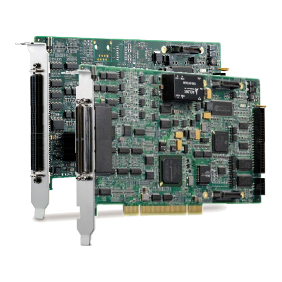
Dimension in unit of millimeter (mm). NOTE NOTE Figure 2-1: Exterior of your PCI-8254 P1: for Motion control command, Position feedback, and Servo I/O feedback. (with SCSI 100-PINS connector) P2: for 16 channel digital TTL input and 16 channel digital TTL output. -
Page 27: Figure 2-2: Exterior Of Your Pci-8258
PCI-8254 / PCI-8258 Figure 2-2: Exterior of your PCI-8258 P1: for Motion control command, Position feedback, and Servo I/O feedback. (with SCSI-VHDCI 200-PINS connector) P2: for 16 channel digital TTL I/O. (with DSUB 37-PINS connector) SW2: Card ID setup (0-15) -
Page 28: Hardware Installation
2.3 Hardware Installation 2.3.1 Hardware Configuration PCI-8254/58 employs PCI Rev. 2.2 bus. System BIOS can auto configure memory and IRQ channel. Exclusive terminal board DIN-825-GP4 provides isolation circuit and indicator lights for easy connection to varieties of servo drive and stepper drive. -
Page 29: Troubleshooting
PCI-8254 / PCI-8258 2.3.3 Troubleshooting If the computer cannot power on normally or the motion control system operates abnormally after system installation, please follow steps described below for troubleshooting. If the problem persists after you have taken steps described, please consult the dealer where your product is purchased for technical services. -
Page 30: Software Installation Procedure
2.4 Software Installation Procedure Windows driver installation procedure: Step 1. Execute PCI-8254/PCI-8258 WDM file and run installation procedure automatically. Step 2. Click "Next" as prompted to complete the installation process. Getting Start with The Installation... - Page 31 PCI-8254 / PCI-8258 Step 3. Restart your computer after installation is completed. Step 4. Ensure the Windows Device Manager identify your PCI-8254/PCI-8258 correctly. Note: Recommendations: Please download latest installation software from ADLINK official website to maintain the optimum operation environment.
-
Page 32: Definitions To Key Connector Signal
2.5 Definitions to Key Connector Signal 2.5.1 PCI-8254: Connector • P1 Name I/O Function of Axis Name I/O Function of Axis DGND Digital ground IEMG Emergency stop input DGND Digital ground Rsv. Reserved AGND Analog ground AGND Analog ground AGND... - Page 33 PCI-8254 / PCI-8258 Name I/O Function of Axis Name I/O Function of Axis EZ1+ Encoder Z-phase (+),(1) EZ3+ Encoder Z-phase (+),(3) EZ1- Encoder Z-phase (-),(1) EZ3- Encoder Z-phase (-),(3) EA2+ Encoder A-phase (+),(2) EA4+ Encoder A-phase (+),(4) EA2- Encoder A-phase (-),(2)
-
Page 34: Pci-8258: P1-A/B Connector
2.5.2 PCI-8258: P1-A/B Connector • P1-A Name I/O Function of Axis Name I/O Function of Axis DGND Digital ground IEMG Emergency stop input DGND Digital ground Rsv. Reserved AGND Analog ground AGND Analog ground AGND Analog ground AGND Analog ground AOUT1+ Analog output (+),(1) AOUT3+... - Page 35 PCI-8254 / PCI-8258 Name I/O Function of Axis Name I/O Function of Axis EA2+ Encoder A-phase (+),(2) EA4+ Encoder A-phase (+),(4) EA2- Encoder A-phase (-),(2) EA4- Encoder A-phase (-),(4) EB2+ Encoder B-phase (+),(2) EB4+ Encoder B-phase (+),(4) EB2- Encoder B-phase (-),(2)
- Page 36 Name Function of Axis Name Function of Axis AOUT5- Analog output (-),(5) AOUT7- Analog output (-),(7) AOUT6+ Analog output (+),(6) AOUT8+ Analog output (+),(8) AOUT6- Analog output (-),(6) AOUT8- Analog output (-),(8) AIN5 Analog input, (5) AIN7 Analog input, (7) AIN6 Analog input, (6) AIN8...
-
Page 37: Pci-8254/58: P2 Connector
PCI-8254 / PCI-8258 Name Function of Axis Name Function of Axis SVON5 Servo-ON, (5) SVON7 Servo-ON, (7) PEL5 Positive limit, (5) PEL7 Positive limit, (7) ZSP5 / Zero Speed (5) / ZSP7 / Zero Speed (7) / INP5 In-Position (5) -
Page 38: Dip Switch
2.6.1 S1: Analog Output Mode Settings This switch is used for switching analog command output modes with default settings at differential type output. In general, you adjust according to individual servo drive interface. The PCI-8254 model uses switches 1-4 only. differential mode... -
Page 39: Sw2: Card Id Switch
PCI-8254 / PCI-8258 2.6.2 SW2: Card ID Switch This switch is used for adjusting card ID for easy identification in user application programs. Take example. If you set card ID to ”0-0-0-1” (OFF-OFF-OFF-ON) then the card ID is ”1” and the ID... -
Page 40: Ide 44P - Dsub 37P Bus
2.7 IDE 44p – DSUB 37p Bus This card include one IDE cable from IDE 44 pin to DSUB 37 pin. It is used for PCI-8254 / PCI-8258 P2 extension 16 channel digital input and 16 channel digital output. Getting Start with The Installation... -
Page 41: Exclusive Board - Din-825-Gp4
Mitsubishi's J3A and the Yaskawa Sigma V series or other servo or stepper drives with single end open cables. The DIN-825-GP4 board supports both PCI-8254/PCI-8258 and AMP-204C/AMP-208C. DO NOT connect it to other ADLINK's motion controller or it may be damaged. -
Page 42: Definitions To Connector
2.8.1 Definitions to Connector 1. P1: This is one SCSI 100-PINS connector for motion control signals. CMA1 2. CMA1–4: These are four 26-PINS connector for CMA2 connecting to servo CMA3 drive to do S/T mode control and analog CMA4 control commands output. - Page 43 PCI-8254 / PCI-8258 7. J6: This is one 5-PINS connector for connecting to four isolation digital output channel. 8. P2: This is one DSUB 37-PINS connector for connecting to 16 channel digital input signal and 16 channel digital output signal in the controller (TTL).
-
Page 44: Connector: For Connecting To
2.8.2 Connector: For Connecting to PCI-8254/PCI-8258/AMP-204C/AMP-208C • P1: No. Name I/O Function of Axis No. Name I/O Function of Axis DGND Digital ground IEMG Emergency stop input DGND Digital ground Rsv. Reserved AGND Analog ground AGND Analog ground AGND Analog ground... - Page 45 PCI-8254 / PCI-8258 No. Name I/O Function of Axis No. Name I/O Function of Axis EZ1+ Encoder Z-phase (+),(1) EZ3+ Encoder Z-phase (+),(3) EZ1- Encoder Z-phase (-),(1) EZ3- Encoder Z-phase (-),(3) EA2+ Encoder A-phase (+),(2) EA4+ Encoder A-phase (+),(4) EA2-...
- Page 46 Name I/O Function of Axis Name I/O Function of Axis TDI2 TTL input, (2) TDO2 TTL output, (2) TDI3 TTL input, (3) TDO3 TTL output, (3) TDI4 TTL input, (4) TDO4 TTL output, (4) TDI5 TTL input, (5) TDO5 TTL output, (5) TDI6 TTL input, (6) TDO6...
- Page 47 PCI-8254 / PCI-8258 • J2: Name I/O Function of Axis Name I/O Function of Axis DICOM Digital input common EDI2 Isolated digital input, (2) EDI1 Isolated digital input, (1) PEL2 Positive limit, (2) PEL1 Positive limit, (1) ORG2 Origin Signal, (2)
- Page 48 • J5 Name I/O Function of Axis Name I/O Function of Axis I24V Ext. power supply, +24V DOCOM Digital output common IGND Ext. power ground EEMG Ext. Emergency signal DICOM Digital input common 1. Please connect DICOM to external power supply (24VDC in general) if possible.
- Page 49 PCI-8254 / PCI-8258 • IOIF2: Name I/O Function of Axis Name I/O Function of Axis Additional isolated digital Additional isolated digital DI14 input, (9) input, (14) Additional isolated digital Additional isolated digital DI10 DI15 input, (10) input, (15) Additional isolated digital...
- Page 50 • IOIF4: Name I/O Function of Axis Name I/O Function of Axis Additional isolated digital Additional isolated digital DO14 output, (9) output, (14) Additional isolated digital Additional isolated digital DO10 DO15 output, (10) output, (15) Additional isolated digital Additional isolated digital DO11 DO16 output, (11)
- Page 51 PCI-8254 / PCI-8258 • CMA1~CMA4: ALM_RST / DO: This signal may be selected as general purpose digital output signal (EDO) or alarm clearance function (ALM_RST) by switch S1 or S2. NOTE NOTE Getting Start with The Installation...
- Page 52 • CMP1~CMP4: ALM_RST / DO: You may set this signal to general purpose digital output signal (EDO) or alarm clearance function (ALM_RST) by switch S1 or S2. NOTE NOTE Getting Start with The Installation...
-
Page 53: S1, S2: Edo/Alm_Rst Selection Switch
PCI-8254 / PCI-8258 2.8.3 S1, S2: EDO/ALM_RST Selection Switch DIN-825-GP4 is equipped with 4 servo drive reset signals. You may set up CMA1~CMA4 PIN 10 and CMP1~CMP4 PIN 10 for servo drive rest or J6 connector DO.1~DO.4 by switch S1 and S2. - Page 54 Getting Start with The Installation...
-
Page 55: Signal Connection
PCI-8254 / PCI-8258 Signal Connection PCI-8254/PCI-8258 must connect to servo or stepper motor drive with exclusive terminal board DIN-825-GP4. All optical isolation circuit of mechanical relevant I/O and servo relevant I/O are set to DIN-825-GP4 prevent damages primary controller PCI-8254/PCI-8258 from any invalid signal connection to it. This... -
Page 56: Analog Control Command Signal
When servo drive is set to P mode, then pulse command of PCI-8254/PCI-8258 will be used for open-loop control (see Section 3.2). This analog channel is then defined as general purpose output one. -
Page 57: Figure 3-1: Connection Example Of Differential Analog Output Signal
PCI-8254 / PCI-8258 CMAx Pin No Description Signal Name Axis # (x=1~4) (n=1~8) AOUT+ Analog Out Signal, (+) (n) AOUT- Analog Out Signal, (-) (n) PCI-8258 need two DIN-825-GP4 for eight axes motion control functions # 1 controls axes 1 ~ 4 and #2 controls axes 5 ~ 8... -
Page 58: Pulse Command
In general, a servo drive can be set to P/S/T (position/speed/ torque) mode. When control mode is set to P mode, then the pulse command control of PCI-8254/PCI-8258 will be used for open-loop control. In addition to servo drive, the Stepper drive also employs pulse command interface as the primary control input commands. -
Page 59: Figure 3-2: Line Driver Type Pulse Control Command Signal Connec
PCI-8254 / PCI-8258 Either servo motor drive or stepper motor drive employs one of the two input interfaces described below: 1. Line Driver input interface provides better anti noise-resistant and longer wiring length. • Signal connection diagram: Figure 3-2: Line Driver type pulse control command signal connection example 2. -
Page 60: Figure 3-3: Open-Collector Type Pulse Control Command Signal Con
• Signal connection diagram: Figure 3-3: Open-Collector type pulse control command signal connection example To avoid damages to Line Driver components on controller caused by invalid wiring please connect the OUT-, DIR- pins of controller to OUT, DIR pins of motor drive. CAUTION The controller employs Line Driver component -26LS31 with maximum Sink Current at 20mA. -
Page 61: Encoder Input, Ea & Eb & Ez
PCI-8254 / PCI-8258 3.3 Encoder Input, EA & EB & EZ PCI-8254/PCI-8258 provides encoder input channels respectively which accept single end input frequency up to 5MHz with each channel containing EA, EB, and EZ signal. Each group of EA, EB, and EZ signal contains a pair of differential signal, e.g. -
Page 62: Figure 3-4: Line Driver Type Encoder Input Signal Connection Example
• Signal connection diagram: Figure 3-4: Line driver type encoder input signal connection example Signal Connection... -
Page 63: Emergency Stop Input
PCI-8254 / PCI-8258 3.4 Emergency Stop Input PCI-8254/PCI-8258 provides one hardware input emergency stop signal (EMG). If the external emergency stop signal is triggered, all motion control commands will be stopped immediately. In addition, the DIN-825-GP4 is designed to transmit external emergency stop signal to servo/stepper motor drive to stop operation of every motor immediately. -
Page 64: Pel/Mel Input
The Plus Limited Switch (PEL) is used as the mechanical protection switch for movement in the positive direction. When this switch is triggered, the PCI-8254/PCI-8258 stops its positive direction movement immediately. The Minus Limited Switch (MEL) is used as the mechanical protection switch for movement in the negative direction. -
Page 65: Figure 3-6: Mechanical Limit Switch Signal Connection Example
PCI-8254 / PCI-8258 • Signal connection diagram: Figure 3-6: Mechanical limit switch signal connection example Signal Connection... -
Page 66: Org Input
3.6 ORG Input PCI-8254/PCI-8258 provides 4/8 original position switch input channels. Working together with the home movement described in Section 4.3, this function returns the body to its original position (also known as the zero position). See below for corresponding... -
Page 67: Inp / Zsp Input
PCI-8254 / PCI-8258 3.7 INP / ZSP Input PCI-8254/PCI-8258 provides 4/8 In-position (INP) or zero speed detection (Zero-speed (ZSP)) input channel. Working with function described in Section 4.8, it can be used as the trigger source for in-position events of individual motion. In general, when servo drive is set to position mode (P mode), the servo issues a (INP) pulse signal to controller when movement get into position. -
Page 68: Alm Input
3.8 ALM Input PCI-8254/PCI-8258 provides 4/8 servo alarm input channels. Working with function described in Section 4.11 it can be used as the trigger source for motion interrupt event. In general, when abnormality is encountered during servo drive movement, it issues an (ALM) pulse signal to controller for abnormality occurrence. -
Page 69: Svon Output
PCI-8254 / PCI-8258 3.9 SVON Output PCI-8254/PCI-8258 provides 4/8 servo-on output channels and utilize the servo-on signal to enable servo drive for pulse or analog commands input. If there is abnormality encountered during movement, PCI-8254/PCI-8258 turns this signal automatically and stops all motion control commands. See below... -
Page 70: Analog Input Signals
3.10 Analog Input Signals PCI-8254/PCI-8258 provides 4/8 analog input channels with 12-bit resolution and 100KHz sampling rate. You may use these analog input channels to get values from voltage sensor. See below for corresponding pins of analog input signals on DIN-825-GP4:... -
Page 71: Compare & Trigger Output
PCI-8254 / PCI-8258 3.11 Compare & Trigger Output PCI-8254/PCI-8258 provides 2/4 comparing trigger pulse output channels. Each comparing trigger channel can output pulse commands up to 1 MHZ. See Section 4.9.2 for its detail and how to use it. See below for corresponding pins of pulse command... -
Page 72: Figure 3-13: Open-Collector Type Compare Trigger Signal Connection
2. Open-Collector interface: Figure 3-13: Open-Collector type compare trigger signal connection example Signal Connection... -
Page 73: Digital Output/Input
PCI-8254 / PCI-8258 3.12 Digital Output/Input PCI-8254/PCI-8258 provides 20/24 digital output/input channels. See below for corresponding pins of general purpose digital input and output signals on DIN-825-GP4: J1/J2 Pin No. Signal Name Description EDI(3) / EDI (1) General purpose digital input signal (3), (1) -
Page 74: Figure 3-14: General Purpose Digital I/O Signal Connection Example
• Signal connection diagram: Figure 3-14: General purpose digital I/O signal connection example Signal Connection... - Page 75 PCI-8254 / PCI-8258 IOIF1 Pin No. Signal Name Description DI(1)~(8) General purpose IOIF2 digital input signal (1)~(8) IOIF2 Pin No. Signal Name Description DI(9)~(16) General purpose digital input signal (9)~(16) IOIF3 Pin No. Signal Name Description Axis # DO(1)~(5) General purpose digital output signal (1)~(5) ※1~5...
- Page 76 • Signal connection diagram: DIN-825-GP4 Switch Type DICOM2 IOIF1 IOIF2 Type PS2805 PCI-8254/PCI-8258 DOCOM DIN-825-GP4 IOIF3 IOIF4 DICOM2 TDO 1~5 DO 1~5 PS2802 PCI-8254/PCI-8258 DOCOM2 DOCOM2 Signal Connection...
-
Page 77: Figure 3-15: General Purpose Digital I/O Signal Connection Example
PCI-8254 / PCI-8258 DIN-825-GP4 IOIF3 IOIF4 DICOM2 TDO 6~16 DO 6~16 PS2802 PCI-8254/PCI-8258 DOCOM2 Figure 3-15: General purpose digital I/O signal connection example Signal Connection... - Page 78 Signal Connection...
-
Page 79: Motion Control Theory
PCI-8254 / PCI-8258 Motion Control Theory This chapter introduces you the motion control function of PCI-8254 / PCI-8258 as well as relevant precautions in using them. Contents: Section 4.1: Motion Control Mode and Interface Overview Section 4.2: Closed-loop Control Section 4.3: Motion Control Operations Section 4.4:... -
Page 80: Motion Control Mode And Interface Overview
4.1 Motion Control Mode and Interface Overview This section describes basic setups of "PCI-8254" and "PCI-8258" before doing motion control and fundamental concepts of its core operations. 4.1.1 Motion Control Interface 4.1.1.1 Control Mode and Output Interface You may use the MotionCreatorPro2 application program to set... -
Page 81: Figure 4-1: Format Of Pulse Signal
PCI-8254 / PCI-8258 In this mode users must pay special attention to pulse signal format acceptable to the motor to be driven. The motor works normally only when being driven by correct pulse format signal, otherwise the motor may fail to work in erroneous direction or with abnormal shaking. -
Page 82: Figure 4-2: Illustration Of Analog Command Output
4.1.1.3 Analog Type The analog control mode is used to control servo motor in velocity mode or torque mode that accepts signals in analog voltage. In this mode the closed-loop function will be initiated automatically. See figure below for closed-loop illustration. See Chapter 2: Close loop control for relevant PID close loop function. -
Page 83: Table 4-1: Encoder Input Format
PCI-8254 / PCI-8258 4.1.1.4 Encoder The position encoder of this controller supports 9 kinds of digital signal input formats as described below. Please set up the position encoder before doing motion control. This is especially true for analog output type closed-loop control as invalid setup may lead to motor burst. -
Page 84: Table 4-2: Encoder Input Format
• Axis parameter setup: Param. No. Define symbol Description 80h (128) PRA_ENCODER_MODE Encoder input signal format 85h (133) PRA_ENCODER_DIR Encoder counting direction setup Table 4-2: Encoder input format • Axis parameter setup API: APS_set_axis_param (); // write in axis parameter APS_set_axis_param ();... - Page 85 PCI-8254 / PCI-8258 4.1.1.5 Motion Control I/O Some motion control I/O signal of this controller definition are summarized in table below: Defined Param. Type Description Symbol Input Servo alarm Input Plus end limit Input Minus end limit Input Home input...
- Page 86 • Signal direction These signal logic may be inverted by software. Relevant axis parameters are listed below: • Board parameter Param. No. Define symbol Description 00h (0) PRA_EL_LOGIC PEL/MEL input logic 01h (1) PRA_ORG_LOGIC ORG input logic 04h (4) PRA_ALM_LOGIC Set ALM logic PRA_ZSP_LOGIC / 05h (5)
-
Page 87: Control Cycle
PCI-8254 / PCI-8258 4.1.2 Control Cycle The controller features three control cycle for different works. They are: 1. Servo control cycle 2. Motion control cycle 3. Host control cycle 4.1.2.1 Servo Control Cycle The servo control cycle is the time required to complete one close loop control. -
Page 88: Figure 4-3: Control Cycle
XXXX 運動控制占用時間 XXXX 系統工作占用時間 Motion control cycle 運動控制週期 Time 時間 Host Control Cycle 系統工作週期 Figure 4-3: Control cycle The motion program is executed in motion control cycle to control jobs to be executed in each motion control cycle directly for more precise completion of realtime jobs. -
Page 89: Closed-Loop Control
PCI-8254 / PCI-8258 4.2 Closed-loop Control 4.2.1 Close-loop Control Overview The close-loop control system works like this: after a command is sent, a group of sensors get system output signals during motion process and returned to the controller, a error signal then can derived by comparing the original command against the feedback signal which is then returned to controller. - Page 90 b Integral Control Integral control can reduce Steady-state error and suppress noise at the expense of system Response time. c Derivative Control The derivative control improves Temporary response time and relative steadiness but helps little in reducing noise and steady state error.
- Page 91 PCI-8254 / PCI-8258 Here represents a position command, CmdPos FbkPos represents position feedback, represents speed CmdVel command and CmdAcc represents acceleration command. The PID control plus velocity / acceleration command feedforward control are added here to reduce tracking error of position command and improve control performance.
-
Page 92: Figure 4-4: Pci-8254/Pci-8258 Close Loop Control Structure Diagram
Figure 4-4: PCI-8254/PCI-8258 close loop control structure diagram Figure 4-5: Gain and Gain shiftrelationship diagram Motion Control Theory... - Page 93 PCI-8254 / PCI-8258 Control circuit relevant axis parameter table: Param. Setup Axis parameter name Descriptions Default range PRA_KP_GAIN PID controller proportional gain 0~65535 PRA_KI_GAIN PID controller integral gain 0~65535 PRA_KD_GAIN PID controller derivative gain 0~65535 PRA_KVFF_GAIN Velocity feedforward gain 0~65535...
-
Page 94: Auto Servo Tuning
4.2.2 Auto Servo Tuning The auto tuning function is aimed at designing stable and of good performance PID controller in fast pace to provide for common users. For advanced users, extra Manual tuning can be applied by referencing to the auto tuning results to come out controllers more specifically meeting special needs. - Page 95 PCI-8254 / PCI-8258 (1) Data length :You may set up data length to determine number of PID controller's gain value to be calculated by the program. Gain values come out of PID controllers differ from each other as a result of varied measurements and errors cause by other factors despite they are of the same system and algorithm.
- Page 96 In case the auto regulation failed we may try to increase Hysteresis range for better success rate at the expense of overall system band. System band and phase margin can be measured with the Bode plot provided by this control card. See later chapters for detail.
-
Page 97: Figure 4-6: The Auto Fine Tuning Setup Page In Mcp2
PCI-8254 / PCI-8258 Figure 4-6: The auto fine tuning setup page in MCP2 Table 4-3: PCI-8254/8 Auto-Tuning setup Setup Descriptions Setup range Default Offset limit The maximum difference Deviation Limit between position command and feedback. The program stops when this value is >=0... -
Page 98: Manual Servo Tuning
4.2.3 Manual Servo Tuning Manual fine tuning is still necessary for satisfying different needs. change three controller parameters manually: Proportional gain, KP, Integral gain, KI and Derivative gain, KD. You may change velocity or acceleration feedforward gain as required. The manual fine tuning procedure can be executed in setup page signal... -
Page 99: Filter
PCI-8254 / PCI-8258 4.2.4 Filter A filter is designed to pass signal of certain band and attenuate all signals outside of this band. This controller supports two general purpose Biquad filter for each axis as shown in Figure 4-6 while the table below indicates corresponding axis parameters against biquad filter. -
Page 100: Figure 4-7: Structure Of Pci-8254/8 Biquad Filters In Serial Connection
Figure 4-7: Structure of PCI-8254/8 biquad filters in serial connection Relevant axis parameters can be found in table below: Param. Define symbol Description Value Default 132h PRA_BIQUAD0_A1 Biquad filter 0 coefficient -32768~32767 133h PRA_BIQUAD0_A2 Biquad filter 0 coefficient -32768~32767 134h... -
Page 101: Figure 4-8: Ideal Low Pass Filter
PCI-8254 / PCI-8258 Param. Define symbol Description Value Default 13Bh PRA_BIQUAD1_B1 Biquad filter 1 coefficient -32768~32767 13Ch PRA_BIQUAD1_B2 Biquad filter 1 coefficient -32768~32767 13Dh PRA_BIQUAD1_DIV Biquad filter 1 coefficient -32768~32767 4.2.4.1 Low Pass Filter Increase control gains (KP and KD) is commonly adopted approach in improving response speed and accuracy. -
Page 102: Figure 4-9: Simulation Results Of Low Pass Filter With 1000Hz Cutoff
Original Signal Filtered Signal -100 0.01 0.02 0.03 0.04 0.05 0.06 0.07 0.08 0.09 Time(second) (a) 30Hz sine wave Original Signal Filtered Signal -100 0.001 0.002 0.003 0.004 0.005 0.006 0.007 0.008 0.009 0.01 Time(second) (b) 1200Hz sine wave Figure 4-9: Simulation results of low pass filter with 1000Hz cutoff frequency Motion Control Theory... -
Page 103: Figure 4-10: Mcp2 Low Pass Filter Setup Page
PCI-8254 / PCI-8258 Adjustment can be made through the MotionCreatorPro 2 function as shown in figure below. Enter the cutoff frequency and the MotionCreatorPro starts calculation filter parameters automatically for you. You can adjust cutoff frequency from high to low and stop the adjustment process once high frequency noise disappears. -
Page 104: Figure 4-12: An Ideal Notch Filter (A) 50 Hz
4.2.4.2 Notch Filter Notch filter is aimed at eliminating specific resonance frequency. The later occurs when frequency of servo response is close to the Natural frequency of the mechanic system. Take example. Resonance is usually found in servo motor mechanism with two or more coupling motors. - Page 105 PCI-8254 / PCI-8258 Original Signal Filtered Signal -100 0.01 0.02 0.03 0.04 0.05 0.06 0.07 0.08 0.09 Time (second) (a) 50Hz sine wave Original Signal Filtered Signal -100 0.02 0.04 0.06 0.08 0.12 0.14 0.16 0.18 Time(second) (b) 100Hz sine wave...
-
Page 106: Figure 4-13: Simulation Results Of Notch Filter With 100Hz Cutoff Fre
Original Signal Filtered Signal -100 0.01 0.02 0.03 0.04 0.05 0.06 0.07 0.08 0.09 Time(second) (c) 200 Hz sine wave Figure 4-13: Simulation results of notch filter with 100Hz cutoff frequency See figure below for MCP2's notch filter setup page where you can workout relevant filter coefficients according to your specifications. -
Page 107: Bode Plot
Bode Plot 4.2.5.1 Structure Overview The Bode Plot tool provided by your PCI-8254/8258 may display transfer function's frequency responses of Linear Time-Invariant (LTI)system. In general the X-axis of a Bode plot indicates frequency in Log scale while its Y-axis Gain and Phase. - Page 108 Frequency response structure diagram Signal description table Name Symbol Unit Description Sine wave pulse The input of closed-loop system. Error position pulse The input of open-loop system. Controller output pulse The input of plant. Encoder pulse The output of closed-loop system, open-loop system, and plant.
- Page 109 PCI-8254 / PCI-8258 a Set up initial and closing frequency and data points of Bode plot: The frequency range of a Bode plot is determined by its initial and closing frequency. As too small a initial value may boost calculation time, please try to start at around 10Hz.
- Page 110 e Set up protection mechanism: Set up a protection mechanism to power off the motor automatically when the error position is exceeding this deviation limit. Set the limit to zero to close this mechanism. In addition, the motor automatically turns off when a warning or emergency signal is encountered.
- Page 111 PCI-8254 / PCI-8258 MCP2 Bode plot page Motion Control Theory...
-
Page 112: Motion Control Operations
4.3 Motion Control Operations This section describes motion control modes provided by the controller and their operation principle. The objective is to help users make most of the motion control capacity of your controller to accomplish desired applications. 4.3.1 Coordinated System This controller employs Cartesian coordinate system where one or more axes motion can be executed by one-to-one mapping each axis to a motor. -
Page 113: Unit Factor
PCI-8254 / PCI-8258 I32 APS_get_command( I32 Axis_ID, I32 *Command ); I32 APS_set_command(I32 Axis_ID, I32 Command); I32 APS_get_position( I32 Axis_ID, I32 *Position ); I32 APS_set_position (I32 Axis_ID, I32 Position); API listed below can read motor coordinates I32 APS_get_encoder( I32 Axis_ID, I32 *Encoder );... - Page 114 Unit factor can be calculated as described below: 10000 × μ × 1000 Example 2: Conveyor system Assume number of pulses generated by one spin of the motor is 8192, the conveyor belt shift 5cm by one spin of the belt pulley, the gear ratio is 1:2, and the user desired distance unit of measure is Millimeter then the Unit factor can be calculated as: Picth= 5 cm...
- Page 115 PCI-8254 / PCI-8258 Unit factor can be set up in axis parameter: Param. No. Define symbol Description Value Default 86h (134) Unit factor F64 value In general, you should define unit of measure at first and set up other position relevant parameter before designing any motion control application.
-
Page 116: Acc/Deceleration Profile
4.3.3 Acc/Deceleration Profile Basic motion command usually contains: 1. distance; 2. velocity; and 3. acceleration data. This controller plans and calculates Acceleration & deceleration profile based on these motion command parameters to make motion operation completed as desired by users. This controller provides following acceleration profiles 1. -
Page 117: Figure 4-18: Maximum Speed By Auto-Planning
PCI-8254 / PCI-8258 In a V-T chart the area under the trapezoidal curve equals motion distance. If the user does not set up sufficient motion distance, the controller shall increase (decrease) the maximum speed while maintain the acceleration, as shown in figure below:... - Page 118 4.3.3.2 S-curve An S-curve is a curve where the speed profile in the jerk area can be represented by second-order profile. This helps to reduce motor vibration at start up and stop time as indicated by points (t1, t3, t5, t7) in figure below. To shorten acceleration and deceleration time the linear section (t2, t6) is inserted in these area to maintain the maximum acceleration and so get an acceleration-time (A-T) chart in Trapezoidal.
- Page 119 PCI-8254 / PCI-8258 This controller employs S-factor (S) to control jerk ratio. Its equation is described below Value of S is between 0 and 1, when S = 0, the speed profile becomes a T-curve S >0 and S<=1: S - curve When S = 1, the profile comes to a Pure S–...
-
Page 120: Figure 4-20: Maximum Speed By Auto-Velocity
Velocity MaxVel MaxVel’ Start velocity Time Acce. Acceleration Time Jerk Time Figure 4-20: Maximum speed by auto-velocity Acceleration profile and its rule described above applies with single axis point-to-point movement (PTP), velocity movement, home movement, and interpolation among multiple axis. Motion Control Theory... - Page 121 PCI-8254 / PCI-8258 • Relevant axis parameters Param. No. Define symbol Description 12h (18) PRA_HOME_CURVE Home move S-factor 20h (32) PRA_SF Move S-factor 42h (66) PRA_JG_SF Jog S-factor You may set up S-factor directly in some API, please refer to Function library manual for detail.
-
Page 122: Home Move
4.4 Home Move After power on and before executing any motion control, a motion control system executes home movement to set up the zero position of the coordinate system. Commonly available stepper motor, servo drive or linear motor mechanism accompanied by optical scale employs incremental type encoder which requires some mechanical signal to set up the original position during home operation. - Page 123 PCI-8254 / PCI-8258 Param. No. Define symbol Description Home position and shift distance of positioning 17h (23) PRA_HOME_SHIFT signal 18h (24) PRA_HOME_EZA EZ alignment enable 19h (25) PRA_HOME_VO Homing velocity away from ORG signal 1Bh (27) PRA_HOME_POS Position command setup after homing completion •...
- Page 124 // 2. Start home move return_code = APS_home_move( axis_id ); //Start homing if( return_code != ERR_NoError ) /* Error handling */ // 3. Wait for home move done, Sleep( msts = APS_motion_status( axis_id );// Get motion status msts = ( msts >> MTS_NSTP ) & 1; // Get motion done bit }while( msts == // 4.
-
Page 125: Ogr Signal Homing - Home Mode = 0
PCI-8254 / PCI-8258 This controller provides multiple auto-home searching process for different hardware platform which may refer to three mechanical signals: ORG, EL, and EZ. You may define three homing mode with these reference signal. User may design required homing process by any combination of these three signals. -
Page 126: Figure 4-21: Home Mode 0 (Case: Org)
• Relevant axis parameters setup Axis Axis parameters parameter Description to axis parameter value values PRA_HOME_MODE Employing home mode 0 (homing by ORG signal) PRA_HOME_DIR Homing by moving forward in positive direction PRA_HOME_EZA Further align with signal EZ, 0: No, 1: Yes PRA_HOME_S S-curve factor Acceleration and deceleration in unit of (distance unit... - Page 127 PCI-8254 / PCI-8258 ORG signal of most mechanical device has two directional edges (the two ends of signal fender). Figure above indicates that when the homing direction parameter in axis parameters is set to positive direction (PRA_HOME_DIR), the control axis starts searching from positive direction (the ascending direction of position command).
-
Page 128: Figure 4-22: Home Mode 0 (Case: Org)
Condition A Home Position Condition B Initial position Condition C Initial position Home position VM: Home searching speed VO: Home approaching speed Figure 4-22: Home mode 0 (Case: ORG) When axis parameter PRA_HOME_EZA is set to 1 it means to align with EZ, move forward to homing direction, until the first EZ is detected and place control axis at the edge of EZ, then the home movement is completed. -
Page 129: Figure 4-23: Home Mode 0 (Case: Org+Ez)
PCI-8254 / PCI-8258 Axis Axis parameters parameter Description to axis parameter value values Speed of original position searching in unit of PRA_HOME_VM (distance unit of measure/sec.) Homing speed in unit of (distance unit of PRA_HOME_VO measure/sec.) Shift amount of homing position (distance unit of... -
Page 130: Figure 4-24: Home Mode 0 Adverse (Case: Org+Ez)
Axis Axis parameters parameter Description to axis parameter value values Acceleration and deceleration in unit of (distance unit PRA_HOME_ACC of measure/sec. PRA_HOME_VS Initial speed in unit of (distance unit of measure/sec.) Speed of original position searching in unit of PRA_HOME_VM (distance unit of measure/sec.) Homing speed in unit of (distance unit of PRA_HOME_VO... -
Page 131: Figure 4-25: Home Mode 0 Decelerate To Stop (Case: Org)
PCI-8254 / PCI-8258 • Relevant axis parameters setup Axis Axis parameters parameter Description to axis parameter value values PRA_HOME_MODE Employing home mode 0 (homing by ORG signal) PRA_HOME_DIR Employing positive direction forward homing PRA_HOME_EZA Further align with signal EZ, 0: No, 1: Yes... -
Page 132: El Signal Homing - Home Mode 1
4.4.2 EL Signal Homing - Home Mode 1 This is a home movement based on PEL or MEL mechanical signal. After the homing command is received, the control axis searches PEL or MEL signal position and stops at edge of the signal. You may set up to align with EZ signal and to set up shift amount. - Page 133 PCI-8254 / PCI-8258 EL homing mode: Positive direction home movement with control axis stops at edge of PEL signal For EL signal homing mode with negative direction homing and without EZ alignment, the control axis stops at MEL signal edge after home movement is completed as shown in figure below.
-
Page 134: Figure 4-27: Home Mode 1 (Case: El+Ez)
Condition A Initial position Home position Initial position Condition B VM: Home searching speed VO: Home approaching speed Figure 4-27: Home mode 1 (Case: EL+EZ) For EL signal homing mode with negative direction homing and EZ alignment, the control axis stops at EZ signal edge after home movement is completed as shown in figure below: Condition A Initial position... -
Page 135: Single Ez Signal Homing
PCI-8254 / PCI-8258 4.4.3 Single EZ Signal Homing Most linear motor mechanism set up only one position mark signal. This mode is used in the said mechanism. Figure below illustrates how to set up Home mode 2 (single EZ signal) with positive direction homing. After home movement is completed the control axis stops at the edge of EZ signal. -
Page 136: Figure 4-28: Home Mode 2 (Case: Ez)
Condition A Home position Condition B Initial position Home position VM: Home searching speed VO: Home approaching speed Figure 4-28: Home mode 2 (Case: EZ) Figure below set up "Home mode 2 (single EZ signal)" with negative direction homing. After home movement is completed the control axis stops at the edge of EZ signal. -
Page 137: Figure 4-29: Home Mode 2 Adverse (Case: Ez)
PCI-8254 / PCI-8258 Condition A Initial position Condition B Home position Initial position VM: Home searching speed VO: Home approaching speed Figure 4-29: Home mode 2 adverse (Case: EZ) In this mode parameter PRA_HOME_EZA is functionless NOTE NOTE Motion Control Theory... -
Page 138: Velocity Move
4.5 Velocity Move In this motion mode, the motion axis move along specified speed profile after proper command is received. Movement continues untill a stop movement command is received. In velocity movement mode functions listed below are supported: • Dynamic changing maximum speed: You may change to any maximum speed during movement. - Page 139 PCI-8254 / PCI-8258 • Example 1: Set up parameters and start up velocity movement. See below for example process: 1. Change maximum speed after 2 seconds 2. Change maximum speed after 2 seconds 3. Stop by deceleration after 2 seconds #include "APS168.h"...
- Page 140 Motion control input signal EMG, ALM, PEL, and MEL may lead to termination of movement, please refer to sections about safety protection CAUTION In velocity movement mode the target position may be updated from time to time as the command position does. CAUTION Motion Control Theory...
-
Page 141: Jog Move
PCI-8254 / PCI-8258 4.6 Jog Move Jog operation is commonly available at control panel of machine. Its main function is to manually control the movement of motion axis or function together with mechanical switch with digital input to use DI signal as the jog movement startup signal. You may use switch on control panel to operate jog movement by setting up relevant parameters instead of coding control program. -
Page 142: Figure 4-31: Jog Step Mode
2. Step mode: In addition to velocity parameters this mode requires specific offset and so is easy for stop position prediction. After the JOG-ON control signal is triggered at the rising edge, the axis being controlled moves a distance of given offset then stops, pauses for a period of time (known as the delay time), if the control signal remains ON in delay time, the control axis moves in given speed profile until the signal disappears. - Page 143 PCI-8254 / PCI-8258 • Relevant axis parameters Parameter Parameter definition Meaning of parameter value code 40h () PRA_JG_MODE Set up JOG mode [0: Continuous, 1: Step] 41h () PRA_JG_DIR Set up JOG direction: [0: Negative, 1: Positive direction] 42h ()
- Page 144 1. Motion control input signal EMG, ALM, PEL, and MEL may lead to movement termination. Please refer to safety protection related NOTE NOTE sections. 2. In continuous mode the target position may be updated from time to time (so does the command position).
-
Page 145: Point-To-Point Move
PCI-8254 / PCI-8258 4.7 Point-to-Point Move 4.7.1 Point-to-Point Move Point-to-Point movement (PTP movement) is to move one axis from position A to position B at given speed. PTP movement can be relative or absolute movement based on its given position parameter. -
Page 146: Synchronous Start
Relevant APS API described below: I32 APS_ptp (); // PTP move I32 APS_ptp_v (); // PTP move with maximum speed parameter I32 APS_ptp_all (); // PTP move with all speed parameter I32 APS_relative_move (); // Relative PTP move in I32 data format I32 APS_absolute_move ();... -
Page 147: On The Fly Change
PCI-8254 / PCI-8258 4.7.3 On The Fly Change You may dynamically change position and velocity parameter in PTP movement process by methods described below: 1. Dynamically change to new position while the velocity parameter remain intact. 2. Dynamically change the maximum velocity while target position remain intact. -
Page 148: Figure 4-34: Continuous Three Position V-T Chart
Take example. V-T chart with 3 continuous PTP movements and different speed blending settings: 1. Buffered Figure 4-34: Continuous three position V-T chart 2. Blend low: Blend with the one with slower maximum speed Figure 4-35: Continuous three position V-T chart (auto speed connection (1) 3. - Page 149 PCI-8254 / PCI-8258 4. Blend previous: Blend in the maximum speed of the previous one Figure 4-37: Continuous three position V-T chart (auto speed connection (3) 5. Blend next: Blend in the maximum speed of the next Figure 4-38: Continuous three position V-T chart...
-
Page 150: Interpolation
4.8 Interpolation Interpolation is a multi-axes locus movement based on given locus properties, e.g. center of circle and end point, and velocity data. The controller then calculate relations between path and time. Axis involved in interpolation start up at the same time and end at the same time after operation completed. -
Page 151: Figure 4-39: Two-Dimension Straight Line Interpolation
PCI-8254 / PCI-8258 If synthetic velocity is set to V, the velocity of each axes Vn should See figure below for a two dimension straight line interpolation with starting point at S and ending point at E: Y component X compone Figure 4-39: Two-dimension straight line interpolation ΔX and ΔY is the offset at X-axis and Y-axis respectively. -
Page 152: Arc Interpolation
Relevant APS API described below: I32 APS_line (); // multi axes straight line interpolation I32 APS_line_v (); // multi axes straight line interpolation with maximum speed settings I32 APS_line_all (); // multi axes straight line interpolation with all speed settings I32 APS_stop_move ();... -
Page 153: Figure 4-40: Three-Dimension Arc Interpolation (Method 1)
PCI-8254 / PCI-8258 Relevant commands are described below: Function name Description APS_arc3_ca Execute 3-dimension arc interpolation with center, angle, and normal APS_arc3_ca_v vector APS_arc3_ca_all APS_arc3_ce Execute 3-dimension arc interpolation with center and end point APS_arc3_ce_v Limit: Cannot execute half or full circle interpolation... -
Page 154: Figure 4-41: Defining Spatial Normal Vector
Figure 4-41: Defining spatial normal vector • How to determine arc direction and path of multiple laps Use the right-hand grip rule as shown in figure below, where the your thumb indicates normal vector direction and the other four fingers the positive rotating direction. Enter negative value for angle parameter to rotate in opposite direction. -
Page 155: Figure 4-43: Three Dimension Arc Interpolation (Method 2)
PCI-8254 / PCI-8258 Coordinates of end point may have certain error caused by computing accuracy of your computer. To get precise end point position, you may use method 2 to enter exact end position accurately (as described in next section) -
Page 156: Figure 4-44: Three Dimension Arc Interpolation Example
θ Take example. If = 30 degree, then calculation formula Angle (Degree) 30 + 0 x 360 30 + 1 x 360 30 + 2 x 360 30 + (-1) x 360 -330 30 + (-2) x 360 -690 • Example: Figure 4-44: Three dimension arc interpolation example 4.8.2.2 2D Arc Interpolation... -
Page 157: Figure 4-45: Three Dimension Spiral Interpolation (Method 1)
PCI-8254 / PCI-8258 4.8.2.3 Helical Interpolation This controller supports 3-dimension helical interpolation (also known as Spiral–Helix interpolation) as well as multiple input methods to deal with demands of various applications. See below for its setup: Method 1: Given center of circle and angle (Center-Angle) Method 2: Given center of circle and end point (Center-End) Both methods are described below. -
Page 158: Figure 4-46: Three-Dimension Spiral Interpolation (Method 2)
Method 2: Given center of circle and end point (Center-End) See table and figure below for helical curve parameters Parameters Description Center point Center of circle (relative or absolute) Normal vector Normal vector of starting point circle plane End point Ending point of cone (relative or absolute) Direction Rotating direction and laps... - Page 159 PCI-8254 / PCI-8258 All helical interpolation input methods described above requires giving normal vector. If there is error with the normal vector, the controller corrects it automatically. See Section 4.8.2 Arc interpolation for correction method. Relevant APS API described below:...
-
Page 160: Continuous Interpolation
4.8.3 Continuous Interpolation With continuous interpolation the controller continuously executes multiple interpolation paths including straight line, arc and helical interpolations described above. You do continuous interpolation by giving multiple interpolation commands in sequence. These commands shall be saved in buffer of the controller queueing for execution. -
Page 161: Figure 4-48: Velocity Blending (Method 1)
PCI-8254 / PCI-8258 You can set up this with input parameter "Flag". See ASP API user manual for detailed parameter description. In essence, the first three methods, method (1), (2) and (3), stops any running interpolation when new interpolation command is received and start executing the new interpolation command immediately. -
Page 162: Figure 4-49: Velocity Blending (Method 2)
2. Aborting forced Characteristic of this kind of command is that the track transfer to new command immediately. The controller makes no smoothing treatment and so the motion track match with the command exactly. In this mode speed component of each axes may become un-smooth. -
Page 163: Figure 4-51: Velocity Blending (Method 4)
PCI-8254 / PCI-8258 4. Buffered When new interpolation command is received it is saved in motion buffer first. Commands in queue then continues to execute after the original interpolation command is finished. Take figure below. When executing a straight line interpolation command from S1 to E1, a "buffered"... -
Page 164: Figure 4-53: Velocity Blending (Method 6)
6. Blending when residue-distance met The controller saves newly received command in motion buffer first. You may set up an offset amount, e.g. the so called residual distance as shown in figure below, and start the new interpolation command for blending after the distance of original interpolation command path from target position is smaller than the residual distance (E1) as shown in figure below. -
Page 165: Figure 4-55: Continuous Interpolation Examples
PCI-8254 / PCI-8258 • Example: Figure 4-55: Continuous interpolation examples Motion Control Theory... -
Page 166: Motion Status Monitoring
4.9 Motion Status Monitoring During the motion control process it is necessary to monitor motion status of control axis and convert to next process control at appropriate time. Take example. During system initialization the upper control program (the control program of user) execute home operation to each control axis at first. -
Page 167: Motion Status
PCI-8254 / PCI-8258 4.9.1 Motion Status Use following API functions to read motion status of each axes: I32 APS_motion_status (); Motion status data of individual axis is combined in return parameter I32 (32 bit integer). See table below for motion status and meaning represented by each bit: Bit No. - Page 168 Bit No. Define Description Jog movement in progress ASTP Clear this signal after next movement is executed The axis is running blending movement Pre-offset event, clear this signal after next PRED movement is executed Post-offset event, clear this signal after next POSTD movement is executed 20~27...
-
Page 169: Figure 4-57: Relation Of Different Motion Signals Vs Motions
PCI-8254 / PCI-8258 Relation between movement and signal shown in figure below: Velocity Time CSTP Time Figure 4-57: Relation of different motion signals VS motions Bit 5: Motion Done – MDN Single movement command or multiple movement command is completed. Single movement command is a single axis point to point movement and multiple axes point to point movement. -
Page 170: Figure 4-58: Relation Of Motion Done (Mdn) Signals Vs Motion
Velocity home() ptp() Time Time Figure 4-58: Relation of motion done (MDN) signals VS motion Bit 6: In Homing signal - HMV When home movement command home () is received at the controller and home movement starts being executed the HMV signal sets NO (=1). -
Page 171: Figure 4-59: Relation Of Motion Done (Mdn), In-Homing (Hmv) Signals
PCI-8254 / PCI-8258 Velocity home() Time Time Figure 4-59: Relation of motion done (MDN), In-homing (HMV) signals VS motion Bit10: Wait Move Trigger – WAIT This signal is set ON when the signal is at status ready for movement triggering. When trigger is sent: Use move_trigger () function to trigger queueing axis. -
Page 172: Figure 4-60: Relation Of Wait Signals Vs Motion
Move_trigger( 0x3 ); Velocity ptp( axis0, MF_WAIT…); Axis 0 Time ptp( axis1, MF_WAIT…); Axis 1 Time Axis0: WAIT Axis1: WAIT Time Figure 4-60: Relation of WAIT signals VS motion Bit11: Point Buffer movement signal - PTB When point buffer movement is started, this signal is set to ON and to OFF when movement is completed. -
Page 173: Figure 4-61: Relation Of Jog And Motion Done(Mdn) Signals Vs Mo
PCI-8254 / PCI-8258 Velocity Time ON(1) JOG-ON 訊號 OFF(0) Time Figure 4-61: Relation of JOG and motion done(MDN) signals VS motion Bit 16: Abnormal stop – ASTP This signal turns on when movement is aborted by certain reasons. See table below for causes to abnormal stop. You may use get_stop_code () function to get abnormal stop code (Stop code). -
Page 174: Figure 4-63: Relation Of Blending (Bld) Signal Vs Motion
Bit 17: Blending movement - BLD Continuous interpolation has several speed succession method. The blending method has a transition region at the interconnection points of two paths (as shown in figure below). The BLD signal indicate that the axis is entering this area. Start deceleration Blending Transition... -
Page 175: Figure 4-64: Relation Between Pre- And Post Distance Event Signals
PCI-8254 / PCI-8258 Velocity Pre-distance Post-distance Time Pre-distance event (PRED) Post-distance event (POSTD) Motion done event (MDN) Time Figure 4-64: Relation between pre- and post distance event signals and movement Motion Control Theory... -
Page 176: Application Functions
4.10 Application Functions 4.10.1 Electronic Gearing Electronic gear function: You may set up movement relation of one axis (slave axis) against another axis (master axis) that is similar to a mechanical gear structure. Relation between two gears is usually expressed with gear ratio. Take example. For a pair of gears with gear ratio 1:2, then the Y (slave) axis rotate 2 turns when the X (master axis) rotate 1 turn. -
Page 177: Figure 4-65: Adjust Electronic Gear's Auto Engagement Speed
PCI-8254 / PCI-8258 Ratio Change gear ratio to ratio-3 Change gear ratio to ratio-2 Ratio 2 Ratio 1 Ratio 3 Time Start gearing A Figure 4-65: Adjust electronic gear's auto engagement speed There are several conditions that may relieve gear relations in standard mode: 1. -
Page 178: High Speed Position Compare Trigger
level 2 position error settings, the controller executes Servo-Off operation to both axes. The setup value of this protection mechanism is to set axis parameter of slave axis by 1: master axis selected to follow and 2: two level of position error protection. Start up gantry mode with APS_start_gear (slave axis ID) after set up is completed. -
Page 179: Figure 4-66: Compare Trigger Block Diagram
PCI-8254 / PCI-8258 Figure 4-66: Compare trigger block diagram TRG / PWM / Timer relevant parameter setup Define Description 0x06 TGR_TRG_EN TRG0~3 output switch Set up TRG0~3 trigger source. You can 0x10~0x13 TGR_TRGx_SRC have multiple sources to choose. 0x14~0x17 TGR_TRGx_PWD... - Page 180 See APS Library operation manual for details on compare trigger relevant parameter list. Set up parameter APIs as described below APS_set_trigger_param (); APS_get_trigger_param (); You may select either encoder counter or internal timer as the source of compare device. Relevant APIs are described below: APS_get_timer_counter ();...
-
Page 181: Figure 4-67: Linear Compare Trigger Example
PCI-8254 / PCI-8258 interval. Linear compare trigger can have compare speed up to 1MHz and integral times of 32 bit comparable points. Use APIs below to set up start point, repeat times and interval of linear compare. APS_set_trigger_linear (); Parameters of linear compare trigger... -
Page 182: Figure 4-68: Table Compare Trigger Example
4.10.2.2.2 Table Compare Trigger Table compare trigger differs from the linear compare trigger in that compare points can be determined by user. That is, intervals between compare points are variable. You may set up any four points (P1~P4) and send triggers when motor reaches each of them as shown in figure below. -
Page 183: Figure 4-69: Table Compare Trigger Block Diagram
No extra program coding is required for loading compare point dynamically in the controller even in case of many compare points. APIs for loading compare table array: APS_set_trigger_table (); APS driver Inside PCI-8254 / PCI-8258 memory Hardware Kernel memory Table array... -
Page 184: Pwm Control (Laser Control) (Vao Table Control)170
The application is highly associated with motion control. To meet this requirements the VAO module is offered by your PCI-8254/8. The VAO module enables quality cutting by controlling laser intensity with speed information. Laser intensity is commonly controlled by pulse-width modulation (PWM). - Page 185 Structure of the VAO module 4.10.3.2 Control Modes Your PCI-8254/8 VAO module now supports three control nodes: a. Mode1: PWM mode This control mode adjust PWM duty cycle according to fixed PWM frequency and variable speeds as shown in figure below. The fixed...
- Page 186 b. Mode 2: PWM frequency mode with fixed width This control mode changes PWM frequency according to speed at fixed PWM pulse width. Under fixed PWM pulse width W, the VAO table gives PWM frequency 1/T , 1/T and 1/T at speed V and V as shown in figure below.
- Page 187 PCI-8254 / PCI-8258 c. Mode 3: PWM frequency mode with fixed duty cycle This control mode changes PWM frequency according to speed at fixed PWM duty cycle. As shown in figure below, the duty cycle and W are the same under varying speed while their frequency and pulse width changes according to the VAO table.
- Page 188 Table below suggests power range and resolution that can be set up by different control modes' VAO tables. Mode Power output range Resolution Duty cycle: 0~2000 1. PWM mode 0.05% (0.05%~100%) 2. PWM frequency mode with Frequency: 3Hz ~ 50MHz 1 Hz fixed width 3.
- Page 189 PCI-8254 / PCI-8258 4.10.3.5 VAO Parameter Table The VAO parameter table helps you in determining settings for control modes and VAO table. See table below on definitions of VAO parameters. Define Description Value Default: 0x00 + (2 * N) VAO_TABLE_OUTPUT_TYPE Table output...
-
Page 190: Table 4-4: Board Parameter Table
output and logic status. See description below for a use case outline. 1. Use APS_set_board_param() to set up PWM output channel and relevant digital output and judgment logic according to the board parameters. 2. Click Option indicated by point table to open DO_Enable, select DO_Channels and DO_ON or DO_OFF. - Page 191 PCI-8254 / PCI-8258 4.10.3.7 Operation Process Examples Operation flow for various control modes are outlined below for your reference. Mode Description 1: PWM mode a. VAO parameter table - APS_set_vao_param () 0x00: set to 1 – PWM mode 0x01: set to 1 – command speed 0x10: set to 1000 –...
-
Page 192: Motion Control And I/O Sampling Function
4.10.4 Motion Control and I/O Sampling Function 4.10.4.1 Sampling Source This control card supports multiple signal sampling for analysis. There are two signal sources: the one belongs to motion kernel signal and the other the close-loop control signal. In figure below, the bottom layer's motion kernel and controller's adjustable update rate is 1ms and 250us respectively, sampling rate of the sampling process is 1ms, and the sampled signals are sent by APS library... -
Page 193: Table 4-5: Motion Kernel Signal Table
PCI-8254 / PCI-8258 Table 4-5: Motion kernel signal table Data Signal name Range Descriptions type Position command: SAMP_SRC_COM_POS Axis 0~7 Integer Unit: pulse Feedback position SAMP_SRC_FBK_POS Axis 0~7 Integer Unit: pulse Command velocity; SAMP_SRC_CMD_VEL Axis 0~7 Integer Unit: pulse/sec Feedback velocity;... -
Page 194: Table 4-6: Closed Circuit Control Signal Table
Data Signal name Range Descriptions type Same as SAMP_SRC_FBK_POS but SAMP_SRC_FBK_POS_F64 Axis 0~7 Double presented in float point numbers Same as SAMP_SRC_CMD_VEL but SAMP_SRC_CMD_VEL_F64 Axis 0~7 Double presented in float point numbers Same as SAMP_SRC_FBK_VEL but SAMP_SRC_FBK_VEL_F64 Axis 0~7 Double presented in float point numbers Same as SAMP_SRC_CONTROL_VOL SAMP_SRC_CONTROL_VOL_F64... - Page 195 PCI-8254 / PCI-8258 Data Signal name Range Descriptions type PID and feedforward control combined PID_CALC_COUNT Axis 0~7 Integer output; Unit: pulse Biquad Filter 0 output; BIQUAD_0_CALC_COUNT Axis 0~7 Integer Unit: pulse Biquad Filter 1 output; BIQUAD_1_CALC_COUNT Axis 0~7 Integer Unit: pulse...
- Page 196 Bit number detail description: Define Description Servo alarm input status Positive end limit Minus end limit Original input (Home input) Emergency stop input Servo index input In-Position input SVON Servo ON output status … SPEL 1: Soft-positive-end limit condition match. SMEL 1: Soft-minus-end limit condition match Note 2: Motion status definition table...
- Page 197 PCI-8254 / PCI-8258 Bit number detail description: Define Description CSTP Command stopped (But it could be in motion) In maximum velocity ACC: In acceleration DEC: In deceleration DIR: Move direction. 1:Positive direction, 0:Negative direction Motion done. 0: In motion, 1: Motion done (It could be abnormal stop) In homing …...
-
Page 198: Simultaneous Move
4.10.5 Simultaneous Move 4.10.5.1 Simultaneous Start Synchronized (Simultaneous) start: This movement can set to be enabled by trigger. When proper command is received, the axis enters a waiting-for-trigger-signal status and starts moving after the trigger is received. When multiple axes are in waiting-for- trigger-signal status you may send trigger signal at the same time for synchronized enabling. - Page 199 PCI-8254 / PCI-8258 After an axis movement is set to startup-by-trigger mode it enters the trigger waiting status, i.e. the WAIT signal of Bit 10 in table below is ON. You may display its signal status with function library, the motion status monitoring function is I32 APS_motion_status ();...
- Page 200 I32 APS_arc3_ca ();I32 APS_arc3_ca_v ();I32 APS_arc3_ca_all ();I32 APS_arc3_ce (); I32 APS_arc3_ce_v ();I32 APS_arc3_ce_all ();I32 APS_arc3_ca ();I32 APS_arc3_ca_v (); I32 APS_arc3_ca_all ();I32 APS_sprial_ca ();I32 APS_sprial_ca_v ();I32 APS_sprial_ca_all (); I32 APS_sprial_ce ();I32 APS_sprial_ce_v ();I32 APS_sprial_ce_all (); b. Send the trigger signal to run synchronized start You may enable multiple axes at the same time by sending trigger signal with function in form of: I32 APS_move_trigger ();...
-
Page 201: Point Table Movement
PCI-8254 / PCI-8258 • Example: #include "APS168.h" #include "APS_define.h" #include "ErrorCodeDef.h" void simultaneous_move_example() //This example shows how to execute a simultaneous move I32 option = 0x100; //bit 8 = 1 I32 return_code = 0; I32 dimension = 2; I32 axis_array[2] = { 0, 1 };... - Page 202 a. Movement parameter setup Please set up movement parameters before executing movement commands including absolute and relative movement, maximum, ending velocity, acceleration and deceleration, S-factor and speed blending method between adjacent paths, for speed and path planning applicable to applications. Please note that these parameter settings are kept by the program memory once being set up.
- Page 203 PCI-8254 / PCI-8258 c. Set movement command to point table The point table offers movement commands of straight line, arc and spiral interpolation which can set movement commands in point table with the paired APS function. Movement Paired APS function...
- Page 204 a. Enable/disable point table function Please enable the point table function, set up its ID (0~1), movement dimension and axis number before using it. Please disable it after the point table function is ended. I32 APS_pt_enable (I32 Board_ID, I32 PtbId, I32 Dimension, I32 *AxisArr);...
- Page 205 PCI-8254 / PCI-8258 • Example: #include "APS168.h" #include "APS_define.h" #include "ErrorCodeDef.h" void pt_move_example () //This example shows how pt move operation I32 ret; I32 Board_ID = 0; I32 PtbId = 0; //Point table 0 I32 Dimension = 2; //2D Dimension I32 AxisArr[2] = { 0, 1 };...
-
Page 206: Safety Protection
4.11 Safety Protection During equipment operation, there maybe errors or situations where emergency stops are required. In case of this, the usual method is to stop the mechanical equipment from operation. This controller provides some safety mechanism to detect predefined error situations. - Page 207 PCI-8254 / PCI-8258 4.11.1.2 Servo Alarm (ALM) See table below for ALM hardware input pins and corresponding axis number: P1A Pin No Signal Name Axis # P1B Pin No Signal Name Axis # ALM1 ALM5 ALM2 ALM6 ALM3 ALM7 ALM4...
- Page 208 EL signal is a hardware input signal including PEL and MEL. PEL is the limit signal in positive direction and MEL the negative direction one. An asserted EL signal causes the controller responses with following actions: 1. If PEL signal is asserted for an axis in positive motion status, the controller stops motion of the axis immediately and error stop code of the axis is set to "4"...
-
Page 209: Software Protection
PCI-8254 / PCI-8258 4.11.2 Software Protection The controller provides software protection mechanism of software limit and position error protection. 4.11.2.1 Soft-limit Signal Software limit functions almost the same as that of the hardware limit with the exception that limit signal is generated by checking location of each axis with the software limit function. - Page 210 When software limit signal is set to ON status the controller responses with following actions: 1. If SPEL signal is asserted for an axis in positive direction motion status, the controller stops motion of the axis immediately and error stop code of the axis is set to "6" (STOP_SPEL) and motion status of axis is set to abnormal stop (ASTP).
- Page 211 PCI-8254 / PCI-8258 4.11.2.3 Watch Dog The watchdog protection mechanism is a timer inside the controller. Timeout of the timer will enable predefined response actions including Servo off, turning off digital output and turning off PWM output. After the watchdog protection mechanism is enabled, the user program must be in responsible status.
- Page 212 3. Reset timer continuously After the watchdog protection mechanism is enabled, the watchdog mechanism should be reset within timeout period to rest the timer and retiming from beginning. In case of timer timeout relevant events are triggered per setting given by step 1.
-
Page 213: Host Interrupt
PCI-8254 / PCI-8258 4.12 Host Interrupt An interrupt is a process starting when specified event is encountered, the device (this controller) issue hardware interrupt signal to the operating system, the operating system enable the driver to execute corresponding interrupt service routine. See figure below for illustration to this flow. - Page 214 See table below for all interrupt event types contained in this controller. Here items 0~7 are interrupt relevant to each control axis, item 8 is system relevant interrupt and item 9 and 10 are digital input interrupt. (Note: For PCI-8254 items 0~3 and 4~7 are reserved.) • Interrupt Item overview:I...
- Page 215 PCI-8254 / PCI-8258 • Axis interrupt events description: bit. Symbol Interrupt event description IALM ALM signal occurrence IPEL PEL signal occurrence IMEL MEL signal occurrence IORG ORG signal occurrence Motor Z phase signal (EZ) occurrence IINP Drive in-place (INP) signal occurrence...
- Page 216 • Item = 8: System interruption events overview Bit No. Factor IHOV IMOV IFCF1 IFCF0 ILCF1 ILCF0 IEMG Bit No. Factor Bit No. Factor Bit No. Factor • System interrupt events description bit. Symbol Interrupt event description IEMG Emergency stop signal (EMG) signal occurrence ILCF0 Linear comparator 0 comparing end ILCF1...
- Page 217 PCI-8254 / PCI-8258 • Item = 9: Digital input rising edge interrupt Bit No. Factor IDIR7 IDIR6 IDIR5 IDIR4 IDIR3 IDIR2 IDIR1 IDIR0 Bit No. IDIR15 IDIR14 IDIR13 IDIR12 IDIR11 IDIR10 IDIR9 IDIR8 Factor (TTL7) (TTL6) (TTL5) (TTL4) (TTL3) (TTL2)
- Page 218 Digital input signal (DI) status changes are detected by controller in every motion cycle. Interrupt can be generated only when the period of external input signal change cycle is CAUTION greater than that of motion cycle. You may use interrupt function in Windows environment as described below: 1.
- Page 219 PCI-8254 / PCI-8258 Detailed operation methods are described below: 1. Set up interrupt events: Use APS_set_int_factor( ) to set up interrupt event for waiting. The function returns interrupt event number if setup is successful. You shall store event number in a parameter to be used by later Wait functions.
- Page 220 • Example: void interrupt_example() // This example shows how interrupt functions work. I32 board_id = 0; I32 int_no; // Interrupt number I32 return_code; // function return code I32 item = 0; // Axis #0 interrupt I32 factor = ( 1 << 12 ); // bit 12 IMDN interrupt //Step 1: , factor = IMDN...
- Page 221 PCI-8254 / PCI-8258 #include <windows.h> // Using event handle #include "APS168.h" #include "ErrorCodeDef.h" void interrupt_with_win32_example() // This example shows how interrupt functions work. I32 board_id = 0; I32 int_no; // Interrupt number DWORD return_code; // function return code I32 item = 0;...
- Page 222 Motion Control Theory...
- Page 223 PCI-8254 / PCI-8258 Important Safety Instructions For user safety, please read and follow all instructions, WARNINGS, CAUTIONS, and NOTES marked in this manual and on the associated equipment before handling/operating the equipment. Read these safety instructions carefully. Keep this user’s manual for future reference.
- Page 224 Never attempt to fix the equipment. Equipment should only be serviced by qualified personnel. A Lithium-type battery may be provided for uninterrupted, backup or emergency power. Risk of explosion if battery is replaced with one of an incorrect type. Dispose of used batteries appropriately. WARNING Equipment must be serviced by authorized technicians when:...
- Page 225 San Jose, CA 95138, USA Tel: +1-408-360-0200 Toll Free: +1-800-966-5200 (USA only) Fax: +1-408-360-0222 Email: info@adlinktech.com ADLINK Technology (China) Co., Ltd. Address: (201203) 300 Fang Chun Rd., Zhangjiang Hi-Tech Park Pudong New Area, Shanghai, 201203 China Tel: +86-21-5132-8988 Fax: +86-21-5132-3588 Email: market@adlinktech.com...
- Page 226 84 Genting Lane #07-02A, Cityneon Design Centre Singapore 349584 Tel: +65-6844-2261 Fax: +65-6844-2263 Email: singapore@adlinktech.com ADLINK Technology Singapore Pte. Ltd. (Indian Liaison Office) Address: #50-56, First Floor, Spearhead Towers Margosa Main Road (between 16th/17th Cross) Malleswaram, Bangalore - 560 055, India Tel: +91-80-65605817, +91-80-42246107 Fax:...
Need help?
Do you have a question about the PCI-8254 and is the answer not in the manual?
Questions and answers