Sign In
Upload
Manuals
Brands
ADLINK Technology Manuals
PCI Card
PCI-8254
ADLINK Technology PCI-8254 Controller Manuals
Manuals and User Guides for ADLINK Technology PCI-8254 Controller. We have
1
ADLINK Technology PCI-8254 Controller manual available for free PDF download: User Manual
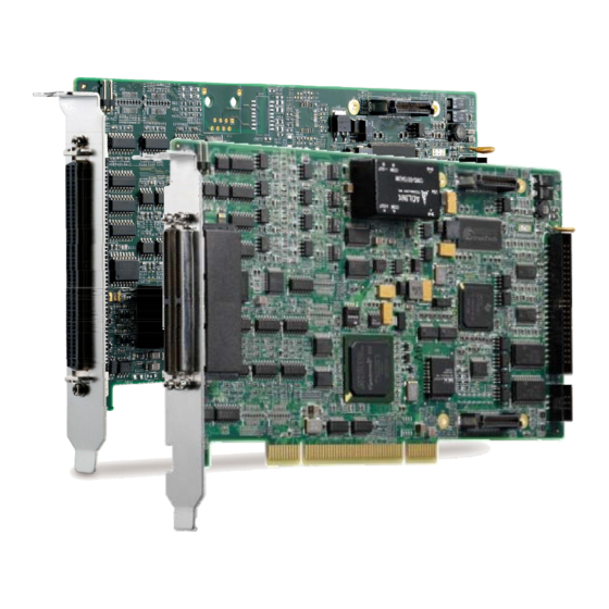
ADLINK Technology PCI-8254 User Manual (226 pages)
DSP-Based 4/8 Advanced Motion Control Card
Brand:
ADLINK Technology
| Category:
PCI Card
| Size: 10 MB
Table of Contents
Preface
3
Table of Contents
5
List of Figures
9
List of Tables
13
Introduction
15
Figure 1-1: PCI-8254/58 System Block Diagram
16
Figure 1-2: System Installation Flow Chart
17
Product Specifications
18
Software Support
22
Software Support Library
22
Motioncreatorpro 2
22
Terminal Board
22
Table 1-1: Cross-Reference Table of Exclusive Cables for Pulse Servo
23
Table 1-2: Cross-Reference Table of Exclusive Cables for Analog Servo
23
Getting Start with the Installation
25
Package Contents
25
PCI-8254/PCI-8258 Exterior Profile Diagram
26
Figure 2-1: Exterior of Your PCI-8254
26
Figure 2-2: Exterior of Your PCI-8258
27
Hardware Installation
28
Hardware Configuration
28
Installation Procedures
28
Troubleshooting
29
Software Installation Procedure
30
Definitions to Key Connector Signal
32
Connector
32
PCI-8258: P1-A/B Connector
34
PCI-8254/58: P2 Connector
37
DIP Switch
38
S1: Analog Output Mode Settings
38
SW2: Card ID Switch
39
IDE 44P - DSUB 37P Bus
40
Exclusive Board - DIN-825-GP4
41
Figure 2-3: Exterior of DIN-825-GP4
41
Definitions to Connector
42
Figure 2-4: Exterior of DIN-825-GP4
42
Connector: for Connecting to
44
Pci-8254/Pci-8258/Amp-204C/Amp-208C
44
S1, S2: EDO/ALM_RST Selection Switch
53
Signal Connection
55
Analog Control Command Signal
56
Single-Ended Type Signal: AOUT
56
Single-Ended Type Signal: AOUT+, AOUT
56
Figure 3-1: Connection Example of Differential Analog Output Signal
57
Pulse Command
58
Figure 3-2: Line Driver Type Pulse Control Command Signal Connec
59
Figure 3-3: Open-Collector Type Pulse Control Command Signal con
60
Encoder Input, EA & EB & EZ
61
Figure 3-4: Line Driver Type Encoder Input Signal Connection Example
62
Emergency Stop Input
63
Figure 3-5: Emergency Stop Signal Connection Example
63
PEL/MEL Input
64
Figure 3-6: Mechanical Limit Switch Signal Connection Example
65
ORG Input
66
Figure 3-7: Original Position Switch Signal Connection Example
66
INP / ZSP Input
67
Figure 3-8: Place / Zero Speed Detection Signal Connection Example
67
ALM Input
68
Figure 3-9: Servo Alarm Signal Connection Example
68
SVON Output
69
Figure 3-10: Servo-On Signal Connection Example
69
Analog Input Signals
70
Figure 3-11: Analog Input Signal Connection Example
70
Compare & Trigger Output
71
Figure 3-12: Line Driver Type Compare Trigger Signal Connection Exam
71
Figure 3-13: Open-Collector Type Compare Trigger Signal Connection
72
Digital Output/Input
73
Figure 3-14: General Purpose Digital I/O Signal Connection Example
74
Figure 3-15: General Purpose Digital I/O Signal Connection Example
77
Motion Control Theory
79
Motion Control Mode and Interface Overview
80
Motion Control Interface
80
Figure 4-1: Format of Pulse Signal
81
Figure 4-2: Illustration of Analog Command Output
82
Table 4-1: Encoder Input Format
83
Table 4-2: Encoder Input Format
84
Control Cycle
87
Figure 4-3: Control Cycle
88
Closed-Loop Control
89
Close-Loop Control Overview
89
Figure 4-4: PCI-8254/PCI-8258 Close Loop Control Structure Diagram
92
Figure 4-5: Gain and Gain Shiftrelationship Diagram
92
Auto Servo Tuning
94
Figure 4-6: the Auto Fine Tuning Setup Page in MCP2
97
Table 4-3: PCI-8254/8 Auto-Tuning Setup
97
Manual Servo Tuning
98
Filter
99
Figure 4-7: Structure of PCI-8254/8 Biquad Filters in Serial Connection
100
Figure 4-8: Ideal Low Pass Filter
101
Figure 4-9: Simulation Results of Low Pass Filter with 1000Hz Cutoff
102
Figure 4-10: MCP2 Low Pass Filter Setup Page
103
Figure 4-11: MCP2 Notch Filter Setup Page
103
Figure 4-12: an Ideal Notch Filter (A) 50 Hz
104
Figure 4-13: Simulation Results of Notch Filter with 100Hz Cutoff Fre
106
Figure 4-14: MCP2 Low Pass Filter Setup Page
106
Figure 4-15: MCP2 Notch Filter Setup Page
106
Bode Plot
107
Motion Control Operations
112
Coordinated System
112
Figure 4-16: Controller Coordinates System Block
112
Unit Factor
113
Acc/Deceleration Profile
116
Figure 4-17: Relation of Trapezoidal Speed Profile's Speed/Accelera
116
Figure 4-18: Maximum Speed by Auto-Planning
117
Figure 4-20: Maximum Speed by Auto-Velocity
120
Home Move
122
OGR Signal Homing - Home Mode = 0
125
Figure 4-21: Home Mode 0 (Case: ORG)
126
Figure 4-22: Home Mode 0 (Case: ORG)
128
Figure 4-23: Home Mode 0 (Case: ORG+EZ)
129
Figure 4-24: Home Mode 0 Adverse (Case: ORG+EZ)
130
Figure 4-25: Home Mode 0 Decelerate to Stop (Case: ORG)
131
EL Signal Homing - Home Mode 1
132
Figure 4-26: Home Mode 1 (Case: EL)
132
Figure 4-27: Home Mode 1 (Case: EL+EZ)
134
Single EZ Signal Homing
135
Figure 4-28: Home Mode 2 (Case: EZ)
136
Figure 4-29: Home Mode 2 Adverse (Case: EZ)
137
Velocity Move
138
Jog Move
141
Figure 4-30: Relation between V-T Chart of JOG Movement and
141
Figure 4-31: Jog Step Mode
142
Point-To-Point Move
145
Figure 4-32: T-Curve V-T Chart
145
Synchronous Start
146
On the Fly Change
147
Continuous PTP Move
147
Figure 4-33: Dynamically Change Position and Velocity
147
Figure 4-34: Continuous Three Position V-T Chart
148
Figure 4-35: Continuous Three Position V-T Chart
148
Interpolation
150
Linear Interpolation
150
Figure 4-39: Two-Dimension Straight Line Interpolation
151
Arc Interpolation
152
Figure 4-40: Three-Dimension Arc Interpolation (Method 1)
153
Figure 4-41: Defining Spatial Normal Vector
154
Figure 4-42: Determining Arc Direction in Space
154
Figure 4-43: Three Dimension Arc Interpolation (Method 2)
155
Figure 4-44: Three Dimension Arc Interpolation Example
156
Figure 4-45: Three Dimension Spiral Interpolation (Method 1)
157
Figure 4-46: Three-Dimension Spiral Interpolation (Method 2)
158
Continuous Interpolation
160
Figure 4-47: Illustration on Continuous Interpolation (Buffer) Move
160
Figure 4-48: Velocity Blending (Method 1)
161
Figure 4-49: Velocity Blending (Method 2)
162
Figure 4-50: Velocity Blending (Method 3)
162
Figure 4-51: Velocity Blending (Method 4)
163
Figure 4-52: Velocity Blending (Method 5)
163
Figure 4-53: Velocity Blending (Method 6)
164
Figure 4-54: Velocity Blending (Method 7)
164
Figure 4-55: Continuous Interpolation Examples
165
Motion Status Monitoring
166
Figure 4-56: Motion Status Monitoring Process
166
Motion Status
167
Figure 4-57: Relation of Different Motion Signals VS Motions
169
Figure 4-58: Relation of Motion Done (MDN) Signals VS Motion
170
Figure 4-59: Relation of Motion Done (MDN), In-Homing (HMV) Signals
171
Figure 4-60: Relation of WAIT Signals VS Motion
172
Figure 4-61: Relation of JOG and Motion Done(MDN) Signals VS Mo
173
Figure 4-62: Relation of ASTP VS Motion
173
Figure 4-63: Relation of Blending (BLD) Signal VS Motion
174
Figure 4-64: Relation between Pre- and Post Distance Event Signals
175
Application Functions
176
Electronic Gearing
176
Figure 4-65: Adjust Electronic Gear's Auto Engagement Speed
177
High Speed Position Compare Trigger
178
Figure 4-66: Compare Trigger Block Diagram
179
Figure 4-67: Linear Compare Trigger Example
181
Figure 4-68: Table Compare Trigger Example
182
Figure 4-69: Table Compare Trigger Block Diagram
183
PWM Control (Laser Control) (VAO Table Control)170
184
Table 4-4: Board Parameter Table
190
Motion Control and I/O Sampling Function
192
Figure 4-70: Signal Sampling Structure Diagram
192
Table 4-5: Motion Kernel Signal Table
193
Table 4-6: Closed Circuit Control Signal Table
194
Simultaneous Move
198
Point Table Movement
201
Safety Protection
206
Hardware Protection
206
Software Protection
209
Host Interrupt
213
Figure 4-71: Interruption Flow Chart
213
Advertisement
Advertisement
Related Products
ADLINK Technology PCI-8174
ADLINK Technology PCI-8136M
ADLINK Technology PCI-8102
ADLINK Technology PCI-8366+
ADLINK Technology PCI-8372+
ADLINK Technology PCI-8570
ADLINK Technology PCI-8154
ADLINK Technology PCI-8258
ADLINK Technology NuDAQ PCI-7258
ADLINK PCIe-GIE74 PRO
ADLINK Technology Categories
Computer Hardware
Motherboard
PCI Card
Control Unit
Desktop
More ADLINK Technology Manuals
Login
Sign In
OR
Sign in with Facebook
Sign in with Google
Upload manual
Upload from disk
Upload from URL