
Related Manuals for SMC Networks AMS20


Summary of Contents for SMC Networks AMS20
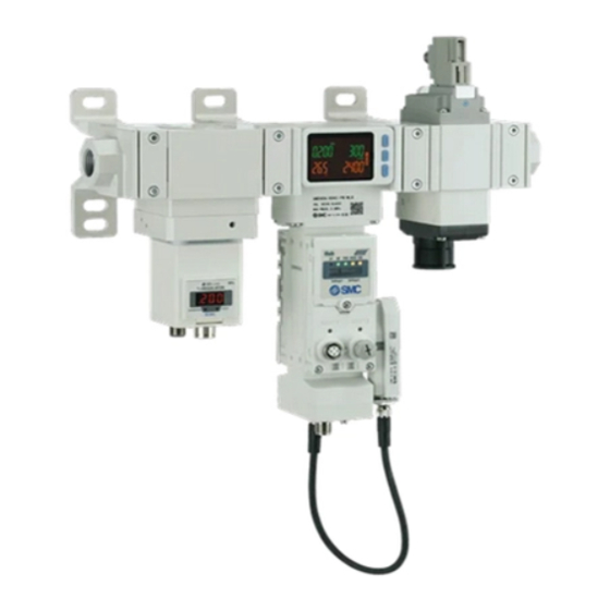
- Page 1 No.PF※※-OMA1007 PRODUCT NAME Air Management System MODEL/ Series/ Product Number AMS20 AMS30 AMS40 AMS60...
-
Page 2: Table Of Contents
Table of Contents Safety Instructions Model Indication and How to Order Names and Functions of Individual Parts Definition and terminology Mounting and Installation Piping Wiring LED indicator System overview Initial Configuration AMS Operation Setting OPC UA Setting PROFINET I/O map Function Setting on Hub Display Function selection mode Default setting... - Page 3 Other Settings Maintenance Forgotten the Security Code Troubleshooting Error display Specifications Characteristics data Dimensions Accessories No.PF※※-OMA1007...
-
Page 4: Safety Instructions
Safety Instructions These safety instructions are intended to prevent hazardous situations and/or equipment damage. These instructions indicate the level of potential hazard with the labels of "Caution", "Warning" or "Danger". They are all important notes for safety and must be followed in addition to International Standards (ISO/IEC) , and other safety regulations. - Page 5 Safety Instructions Caution 1.The product is provided for use in manufacturing industries. The product herein described is basically provided for peaceful use in manufacturing industries. If considering using the product in other industries, consult SMC beforehand and exchange specifications or a contract if necessary. If anything is unclear, contact your nearest sales branch.
- Page 6 ■Operator ♦This Operation Manual is intended for those who have knowledge of machinery using pneumatic equipment, and have sufficient knowledge of assembly, operation and maintenance of such equipment. Only those persons are allowed to perform assembly, operation and maintenance. ♦Read and understand this Operation Manual carefully before assembling, operating or providing maintenance to the product.
- Page 7 Caution ■Do not touch the terminals and connectors while the power is on. Otherwise electric shock, malfunction and damage to the product can result. ■After maintenance is complete, perform appropriate functional inspections and leak test. Stop operation if the equipment does not function properly or there is leakage of fluid. When leakage occurs from parts other than the piping, the product itself may be damaged.
- Page 8 Tighten them to the recommended tightening torque. Insufficient tightening may cause loosening or sealing failure, and excessive tightening may cause damage to the screws. Recommended tightening torque Unit: N•m Applicable models AMS20# AMS30# AMS40# AMS60# Part No. of spacer with bracket...
- Page 9 •Do not apply torsion or bending moment other than the weight of the product itself. External piping needs to be supported separately as it may cause damage. If moment applied to the equipment is unavoidable during operation, the moment should be lower than the maximum moment shown below.
- Page 10 ∗Wiring (Including connecting/ disconnecting of the connectors) •Do not pull hard on the lead wire. Especially never lift the product equipped with fitting and piping by holding the lead wires. Damage to the connector, circuit board, cover or internal components may result, causing failure or malfunction. •...
- Page 11 ∗Operating environment •Do not use the product in an environment where the product is constantly exposed to water splashes. Otherwise failure or malfunction can result. Take measures such as using a cover. •Do not use the product in an environment where corrosive gases or fluids splashes can occur. Otherwise damage to the internal parts can result, causing malfunction.
- Page 12 ∗Adjustment and Operation •Perform settings suitable for the operating conditions. Incorrect setting can cause operation failure. •Please refer to the PLC manufacturer's manual etc. for details of programming and addresses. For the PLC protocol and programming refer to the relevant manufacturer's documentation. •Connect the load before turning the power supply on.
-
Page 13: Model Indication And How To Order
Model Indication and How to Order Air Management System (Standby E/P regulator type) -12- No.PF※※-OMA1007... - Page 14 Air Management System (Standby regulator type) -13- No.PF※※-OMA1007...
- Page 15 Air Management Hub Optional Parts numbers If an accessory is required for maintenance purposes, order the following parts number. Product name Parts number Note Y200T-2-D For body size 20 Y300T-2-D For body size 30 Spacer with bracket Y400T-1-D For body size 40 Y600T-2-D For body size 60 E200-##-D...
-
Page 16: Names And Functions Of Individual Parts
Names and Functions of Individual Parts Air Management System (Standby E/P regulator type) Name Function Control air pressure according to electrical signals from the Air Standby E/P regulator Management Hub. Manage overall Air Management System devices, communication to upper Air Management Hub layer and digital input module for signal from external devices. - Page 17 Air Management System (Standby regulator type) Name Function Standby regulator Control air pressure manually. Manage overall Air Management System devices, communication to upper Air Management Hub layer and digital input module for signal from external devices. According to orders from the Air Management Hub, stop providing pressure and exhaust outlet pressure.
- Page 18 Air Management Hub Part Description Display Please refer to the following page for details. Piping port For piping connections. LED display Displays the Air Management Hub status. Display cover Display cover for switch setting. Display cover screw Screw to secure the display cover. Connector (PORT1) Connector for Industrial Ethernet input.
- Page 19 Display Part Description Displays the instantaneous flow rate, pressure value and error codes. Main display (2 colour display) Indicates the output status of OUT. Operation LED When the output is ON: LED is ON. Displays the accumulated flow, temperature value, set value, and peak/ bottom Sub display value when in measurement mode.
-
Page 20: Definition And Terminology
■Definition and terminology Term Definition The total amount of fluid that has passed through the device. If an instantaneous Accumulated flow flow of 100 L/min lasts for 5 minutes, the accumulated flow will be 5 x 100 = 500 L. A function to store the cumulative flow value in the product's internal memory at certain time intervals. - Page 21 Term Definition Abbreviation of functional earth. The word "earth” refers to functional earth. Abbreviation of full span or full scale; difference between the min. and max. rated pressure values. means the max. fluctuation range of the pressure switch F.S. rated value. (full span/full scale) For example, when the rated pressure range is 0 to 1.000 [MPa]: F.S.
- Page 22 Term Definition The flow which is converted into the volume at 0 C and 101.3 kPa (absolute Normal condition pressure). <nor> indicates that the product is in normal condition. Operating fluid temperature Range of fluid temperature that can be measured by the product. Operating humidity range Humidity range in which the product can operate.
- Page 23 Term Definition Diagnostic function which detects generation of an over current due to a short Short circuit detection circuit between the output and the positive power supply line or the ground line. Function which protects from damage to the internal circuit when over current Short circuit protection is generated due to short circuit between the output and the positive power supply line or the ground line.
-
Page 24: Mounting And Installation
•Tighten the two hexagon socket head cap screws evenly using a hexagonal wrench. •Refer to the table below for the tightening torque for the screws. Applicable model Hexagonal wrench socket size nominal value Tightening torque AMS20# 2 mm 0.36±0.036 N•m AMS30# 3 mm 1.2±0.05 N•m... -
Page 25: Wiring
■Wiring (1) Power M12 4-pin A-coded (Plug) connector is used for the connection between the Air Management Hub and the power supply. Connector Pin No. Signal Details DC(+) 24 VDC Not connected DC(-) Not connected (2) Communication line M12 4-pin D-coded (Socket) Use this port for Industrial Ethernet communication or access to integrated Web server. - Page 26 (3) Connection to each device Refer to the following instructions when device maintenance/replacement is required. AMS components and signals connect to the four connectors on the rear of the Air Management Hub. All connections are M12 A-coded. The following table shows the functions of each port. Port Function Connection to Residual Pressure Relief Valve...
- Page 27 •Connection to Standby regulator Hub side M12 5-pin A-coded (Socket) Connector Pin No. Signal Details 24 V 24 VDC Not connected ITV: IO-Link ARS: Output Not connected Standby E/P regulator (ITV) side M12 5-pin A-coded (Socket) Connector Pin No. Signal Details 24 V 24 VDC...
- Page 28 •User configurable port This port can be configurable by users for digital input/ output/ IO-Link master. M12 5-pin A-coded (Socket) Connector Pin No. Signal Details 24 V 24VDC Digital Input IO-Link Digital Input (PNP) Digital Output (PNP) ∗1 Not Connected ∗1: Can be changed by setting parameters.
-
Page 29: Led Indicator
LED indicator Air Management Hub (Base type) LED colour PROFINET EtherNet/IP Normal operation or the power supply is Power supply is OFF. OFF. Node flashing test command received. Orange flashing Internal communication error in wireless adaptor. Green ON Normal operation. Power supply voltage is abnormal. - Page 30 LED colour Operation PORT1: No Link, No Activity Green ON PORT1: Link, No Activity PORT1 Green Flashing PORT1: Link, Activity PORT2: No Link, No Activity Green ON PORT2: Link, No Activity PORT2 Green Flashing PORT2: Link, Activity -29- No.PF※※-OMA1007...
- Page 31 Air Management Hub (Remote type) LED colour Operation Normal operation or the power supply is OFF. Power supply voltage is abnormal. Green flashing Short circuit of output ports of 24 V port. Red flashing Pairing mode. (synchronized with SA) Red ON Component failure inside the AMS Hub.
- Page 32 Air Management Hub (Port status) Port1(VP) LED colour Operation Output signal OFF. Orange ON Output signal ON. (CQ_1) Red ON Short circuit detected. Port2(ITV/ARS) LED colour Operation Output signal OFF. Orange ON Output signal ON. (ARS) Green flashing IO-Link device not connected. (1 Hz) ITV/ARS Connected device matching error.
- Page 33 Port4(IO-Link) The C/Q_4 LED status varies depending on the setting of Pin No.4 (disabled, IO-Link communication, digital I/O) of port 4. Pin function LED colour Operation Deactivated Port disabled. (Port Red ON Short circuit detected. (24 V) disabled) Green flashing IO-Link device disconnected.
- Page 34 Wireless adaptor LED colour Operation Green ON Power US1 (Control) ON. Red ON Unrecoverable error is detected. US1 (for control) power supply is OFF. Green ON The level of received radio wave power is 3. Green flashing The level of received radio wave power is 2. (1 Hz) W-SS Green flashing...
- Page 35 Standby E/P regulator LED colour Operation Green ON Normal operation. Power LED Green flashing Communication system error. Internal memory error/No power supplied. Green ON IO-Link communication not established. Communication Green flashing IO-Link communication established. No power supplied. -34- No.PF※※-OMA1007...
-
Page 36: System Overview
System overview The AMS consists of three base components. •Standby E/P regulator or Standby regulator: Electrical or manual adjustment of standby pressure. Standby pressure is activated by electrical signal from the Air Management Hub. •Air Management Hub: Measures flow rate, pressure and temperature, manages network communication and controls the composed devices. - Page 37 2. Air Management Hub: Remote type (EXA1-##-SA) The Air Management Hub remote type comes with no data communication. It could be used as standalone. Optionally a wireless adapter can be connected to use the Air Management Hub as a wireless remote.
- Page 38 4. Standby E/P regulator: Electrical pressure setting type (ITV) The electrical pressure setting type uses an ITV module to set the operation pressure and standby pressure. 5. Residual Pressure Relief Valve (VP) A VP valve module can be used for isolation mode with an optional soft start function. The silencer is not included and therefore should be ordered separately.
- Page 39 6. User configurable port Each Air Management Hub has one spare port which can be configured to be either: •1 × DI & IO-Link •1 × DI & 1 × DO •2 × DI Additional compact wireless remotes (EXW1-RD#) can be paired to an AMS wireless base to provide extra digital IO (maximum of 10 wireless remotes per AMS wireless base).
- Page 40 -39- No.PF※※-OMA1007...
- Page 41 ○Working Principle The Air Management System (AMS) functions in three modes: Operation, Standby and Isolation. When the measured flow rate is below a set flow value "1. Standby flow rate (Threshold)" for longer than a set time "2. Standby ON delay" and "3. Standby input signal" is ON (24 VDC by digital input or logic high by PLC or OPC UA), the AMS output pressure will be reduced from the operation pressure down to the user specified "4.
- Page 42 ○Timing Chart The following figure shows an example timing diagram for the NC type AMS##A and NO type AMS##B. This timing chart is for reference only, the actual be haviour depends on the machine volume connected to the AMS outlet side. •AMS##A: NC type •AMS##B: NO type -41-...
-
Page 43: Initial Configuration
Initial Configuration ○DIP Switch setting The hardware setting of the Air Management Hub is configured using Setting 1 DIP switch No.1 to 4. Loosen the display cover screw and open the display cover using a flat head screwdriver. Refer to the flowing table to set the DIP switches. Switch Number Switch Position... - Page 44 AMS functions depending on the DIP switch 1 is as follows. Machine to AMS control Monitor Data AMS Base type Via Digital Via Industrial Ethernet OPC UA Industrial Input Ethernet IO or IO-Link IO or IO-Link disconne Fieldbus OPC UA Switch Standby and Standby and...
- Page 45 ○Web Server connection The Air Management Hub base type has a web server which is used for configuration and maintenance. To access the web server, connect a PC to the network and enter the Air Management Hub IP address into a web browser.
- Page 46 ○Wireless Network Configuration The Air Management Hub can be configured to make a wireless network. Connecting a wireless adapter (EXW1-A11N-X1) to the M8 "ADPTR" port of the AMS will allow wireless communication. ADPTR port Each of the AMS devices need to be set to pairing mode. Starting with DIP switch 4 of SW 1 in the OFF position, perform the sequence ON >>...
-
Page 47: Ams Operation Setting
AMS Operation Setting ○Force AMS mode During configuration it may be necessary to force the AMS into operation mode standby mode or isolation mode. This can be done using the Air Management Hub display and buttons or via the webserver. Refer to [F41] Force AMS Mode setting to set parameter via buttons. - Page 48 ○Standby regulator pressure setting For the ARS type AMS, the operation pressure is the same as the AMS supply pressure. To set the standby pressure, the AMS must first be forced into standby mode. When in standby mode, set the standby pressure by turning the handle on the regulator module.
- Page 49 ○Standby E/P regulator pressure setting For the ITV type AMS, the operation pressure and standby pressure are set using the webserver, ITV buttons or via Fieldbus. •Setting via Webserver To change the operating pressure, Standby Pressure, or pressure ramp up duration, navigate to the "Standby E/P regulator"...
- Page 50 •Setting via buttons To set the operation and standby pressure, press the "S" button once on the ITV, then use the up and down arrows to select PS1 (operation pressure) or PS2 (standby pressure). Press the "S" button again to allow editing and use the arrows to modify the value.
- Page 51 To configure the pressure ramp up duration, hold the "S" button on the ITV until the display shows "F01" and use the up and down arrows to select "F07". Press the "S" button once and edit the value. The value displayed on the screen is seconds x10.
- Page 52 •Parameter setting for Standby mode/Isolation mode. The parameters can be set by Webserver, display buttons on the Air Management Hub or via Industrial Ethernet. Refer to [F40] Standby function setting to set parameter using the buttons. (page 79) Setting via Webserver Navigate to the "Sensor"...
- Page 53 •Parameter Setting Priority The Air Management Hub Base parameter "Overwriting parameter by Record Data" controls the priority for the parameter setting. If enabled, the PROFINET GSDML settings will overwrite the webserver settings. In the webserver, go to the "System Parameter" section of the Air Management Hub Base to change this setting.
-
Page 54: Opc Ua Setting
OPC UA Setting ○OPC UA The Wireless base provides the data from connected remotes via OPC UA. Depending on the OPC UA client used, the AMS Base may require an OPC UA certificate to be installed. ○Communication Specifications Refer to the following table for the AMS OPC UA communication limits. Parameter Value MaxMonitoredItemsPerCall... - Page 55 OOPC UA nodes are user configurable and can be imported and exported via a csv file. Refer to the Process data map to configure user nodes. The "Write Enable" check box enables outputs to be written to by OPC UA. The "Buffer Enable"...
- Page 56 The endian can be changed between big and little. The figure below shows an example of how the process data is mapped for big and little endian. Comparison of big endian and little endian •UaExpert Connection The example below uses the OPC UA client UaExpert to connect the wireless base OPC UA server. Click the plus symbol and then add a "custom discovery"...
- Page 57 Expand the AMS server and select the "None" security option. OPC UA security type Click the "Connect" button and enter the username and password for the AMS (both are "admin"). OPC UA login -56- No.PF※※-OMA1007...
- Page 58 Navigate in the Address Space to the "ParameterSet" and expand it to see all the configured nodes available on the AMS. Server address base -57- No.PF※※-OMA1007...
-
Page 59: Profinet
PROFINET The figure below shows an example AMS configuration in TIA Portal. Select the diagnostic data to use and the wireless base type then add any additional remote units. This example shows a system with full diagnostics, one AMS Base and two AMS remotes. Each AMS component can be configured in Device Overview. -
Page 60: I/O Map
I/O map ○Input map •AMS Base Byte Note System diagnostic information 1 System diagnostic information 2 System diagnostic information 3 System diagnostic information 4 Refer to Standard Remote connection information 1 EX600-W system Remote connection information 2 diagnostics Remote diagnostic information 1 Remote diagnostic information 2 Remote registration information 1 Remote registration information 2... - Page 61 Byte Note 00HEX: Initialising 01HEX: Operation mode 11HEX: Forced Operation mode from button 02HEX: Waiting for standby signal 03HEX: Standby mode 13HEX: Forced Standby mode from AMS status button/OPC UA 23HEX: Force Standby mode from PLC/OPC UA 04HEX: Isolation mode 14HEX: Force Isolation from button/web 24HEX: Force isolation...
- Page 62 •Byte 20 Details Description Value 0: L Accumulated flow unit 1: ft 0: STD Flow Reference Condition 1: NOR 0: Normal Flow rate diagnostic 1: HHH 0: Normal Temperature diagnostic 1: HHH/LLL 0: Normal Pressure diagnostic 1: HHH/LLL 0: No forced Force AMS mode 1: Forced 0: Normal...
- Page 63 ・Byte 24 and 25 Details Description Value 1: Output pressure value is within ±10% of the target value. SSC1 0: Other than the above case. Reserved Notification of the accumulated 1: The accumulated energizing time reaches the set value. energizing time 0: Other than the above case.
- Page 64 •Byte 26 Details Description Details Value 0: No short circuit Air Management Hub internal L+ short circuit or P24 short circuit 1: Short circuited error 1 0: Device not connected Air Management Hub internal Port communication status 1: Operate or Pre-operate error 1 0: No short circuit VP short circuit...
- Page 65 •AMS Remote Byte Note Accumulated flow [high word] Unit: 10 L Accumulated flow [low word] Instantaneous flow [high byte] Unit: L/min Instantaneous flow [low byte] Fluid temperature [high byte] Unit: 0.1 Fluid temperature [low byte] Pressure [high byte] Unit: kPa Pressure [low byte] Flow System...
- Page 66 Byte Note ITV control pressure measurement value [high byte] Unit: kPa ITV control pressure measurement value [low byte] ITV diagnostic data [high byte] ITV diagnostic data [low byte] Port 3 VP short Management Management Reserved short circuit Hub internal Hub internal circuit error 2 error1...
- Page 67 ○Output mapping •AMS Base Byte Isolation input Isolation input Reserved signal for NO signal for NC F-Standby Standby system system Port 4 Digital Reserved Reserved Output Port 4 IO-Link process data Wireless Remote 1 Wireless Remote 10 •Byte 0 Details Description Details Value...
-
Page 68: Function Setting On Hub Display
Function Setting on Hub Display ■Function selection mode In this mode, each function setting can be changed separately. In measurement mode, press the SET button for 3 seconds or longer to display [F 0]. Press the UP or DOWN button to select the function to be changed. Press the SET button for 2 seconds or longer to return to measurement mode. -
Page 69: Default Setting
[Po_E] Not Applicable on this product. [25] AMS series [FrtE] Standby flow rate [50] AMS30 series (Threshold) [100] AMS40 series [200] AMS60 series [100] AMS20 series [FHyS] Standby flow rate [200] AMS30 series [F40] Page (Hysteresis) [300] AMS40 series [400] AMS60 series... -
Page 70: F0 Reference Condition/Units Selection Function
■[F 0] Reference condition/Units selection function Reference condition Standard condition or normal condition can be selected. Standard condition and normal condition are defined as follows: •Standard condition: Displayed flow rate which is converted to volume at 20 °C, 101.3 kPa (absolute pressure). •Normal condition: Displayed flow rate which is converted to volume at 0 °C, 101.3 kPa (absolute pressure). - Page 71 <Operation> Display [F 0] by pressing the UP or DOWN button in function selection mode. Press the SET button. Move on to reference condition. Reference condition Press the UP or DOWN button to select the reference condition. Move on to units selection function. Press the SET button to set.
-
Page 72: F3 Select Digital Filter
■[F 3] Select digital filter The digital filter can be selected to filter the flow rate and pressure measurement. Output chattering or display flicker in measurement mode can be reduced by setting the digital filter. <Operation> Display [F 3] by pressing the UP or DOWN button in function selection mode. Press the SET button. -
Page 73: F6 Fine Adjustment Of Display Value
■[F 6] Fine adjustment of display value This function is used to manually perform a fine adjustment of the displayed pressure value. Pressure can be adjusted in the following range of ±5%R.D. <Operation> Display [F 6] by pressing the UP or DOWN button in function selection mode. Press the SET button. -
Page 74: F13 Setting For Reverse Display Mode
■[F13] Setting for reversed display mode This function is used to rotate the display upside down. It is used to correct the display when it is upside down due to installation of the product. When the reversed display function is ON, the function of the UP/DOWN buttons are reversed. <Operation>... -
Page 75: F14 Zero Cut-Off Setting
■[F14] Zero cut-off setting When the flow rate and pressure is close to zero, this function forces the display to zero. The zero cut-off range is 0.0 to 10.0%F.S., and can be set in 1.0%F.S. increments. <Operation> Display [F14] by pressing the UP or DOWN button in function selection mode. Press the SET button. - Page 76 ●Displayable flow rate range Displayable flow range Zero cut-off Zero cut-off range AMS20 AMS30 AMS40 AMS60 ∗ 0%F.S. 0 to 525 L/min 0 to 1050 L/min 0 to 2100 L/min 0 to 4200 L/min 5 to 525 L/min 10 to 1050 L/min...
- Page 77 ●Displayable pressure range Zero cut-off set value Zero cut-off range Displayable pressure range 0%F.S. -0.050 to 1.050 MPa -0.050 to -0.010 MPa 0 to 1%F.S. 0.010 to 1.050 MPa (Displays 0 when the value is -0.009 to 0.009 MPa) -0.050 to -0.020 MPa 0 to 2%F.S.
-
Page 78: F16 Measurement Display Setting
■[F16] Measurement display setting Display/hide the measured accumulated flow rate, pressure, and temperature can be set. <Operation> Display [F16] by pressing the UP or DOWN button in function selection mode. Press the SET button. Move on to measurement display setting. Measurement display setting Press the UP or DOWN button to select the measurement display setting. -
Page 79: F30 Setting Of Accumulated Value Hold
■[F30] Setting of accumulated value hold In the default setting, the accumulated flow value is not held when the power supply is turned off. This function enables the accumulated flow value to be stored in permanent memory every 2 or 5 minutes. ∗: When using the accumulated value hold function, calculate the product life from the operating conditions, and use the product within its life. -
Page 80: F40 Setting For Standby/Auto Isolation Function
■[F40] Setting for standby/auto isolation function This is the function to set the parameters for standby mode. <Operation> Display [F40] by pressing the UP or DOWN button in function selection mode. Press the SET button. Move on to Standby flow rate (Threshold) Setting of Standby flow rate (Threshold) Set the value based on the setting method on page 81. - Page 81 Setting of auto isolation delay Set the value based on the setting method on page 81. Press the SET button to set. Return to function selection mode. [F40] Complete setting for standby function -80- No.PF※※-OMA1007...
- Page 82 •How to set the value with buttons. (1) Press the SET button once when the item to be changed is displayed on the display. The set value on the sub display (right) will start flashing. (2) Press the UP or DOWN button to change the set value. The UP button is to increase and the DOWN button is to decrease the set value.
-
Page 83: F41 Setting For Force Ams Mode
■[F41] Setting of Force AMS mode Regardless of the conditions and parameters, this function will force the AMS into the selected mode. <Operation> Display [F41] by pressing the UP or DOWN button in function selection mode. Press the SET button. Move on to the setting of Force AMS mode. -
Page 84: F80 Set Display Off Mode
■[F80] Set display OFF mode This function will turn the display OFF if no buttons are pressed for 30 seconds. <Operation> Display [F80] by pressing the UP or DOWN button in function selection mode. Press the SET button. Move on to select display OFF mode. Select display OFF mode Press the UP or DOWN button to select display OFF function. -
Page 85: F81 Security Code
■[F81] Security code The security code can be turned on and off and the security code can be changed when unlocked. <Operation> Display [F81] by pressing the UP or DOWN button in function selection mode. Press the SET button. Move on to select security code. Select security code Press the UP or DOWN button to select security code. - Page 86 Changing of security code. New security code is displayed on the main display. Press the UP or DOWN button to change the value. Press the SET button to move on to input the next digit. After entry, the changed security code will flash by pressing the SET button for 1 second or longer.
-
Page 87: F90 Setting Of All Functions
■[F90] Setting of all functions Each time the SET button is pressed, the function steps in the order shown in the following table. <Operation> Display [F90] by pressing the UP or DOWN button in function selection mode. Press the SET button. Move on to set all functions. -
Page 88: F96 Check Of Cycle Time
■[F96] Check cycle time The average cycle time of the internal bus of the Air Management Hub can be checked. <Operation> Display [F96] by pressing the UP or DOWN button in function selection mode. Press the SET button. Move on to check cycle time. Check cycle time Press the SET button to set. -
Page 89: F98 Setting Of Output Check
■[F98] Setting of output check By forcibly switching the output ON/OFF operation using the button operation, the operation of the system can be checked regardless of the measured value. This function can be checked on Byte20 for Base type or Byte10 for Remote type, please refer to the IO map. <Operation>... - Page 90 Flow rate diagnostic bit check Select the flow rate diagnostic bit check by pressing the UP or DOWN button. Move on to temperature diagnostic Press the SET button to set. bit check. Temperature diagnostic bit check Select the temperature diagnostic bit check by pressing the UP or DOWN button.
- Page 91 Error diagnostic bit check Select the error diagnostic bit check by pressing the UP or DOWN button. Move on to system error diagnostic Press the SET button to set. bit check. System error diagnosis bit check Select the system error diagnostic bit check by pressing the UP or DOWN button.
- Page 92 Flow rate check Press the UP or DOWN button to select the flow rate check. Press the SET button to set. Move on to temperature check. Temperature check Press the UP or DOWN button to select the temperature check. Press the SET button to set. Move on to pressure check.
-
Page 93: F99 Reset To The Default Settings
■[F99] Reset to the default settings If the Flow switch settings are uncertain, the default values can be restored. <Operation> Display [F99] by pressing the UP or DOWN button in function selection mode. Press the SET button. Move on to reset to factory default settings. Rest to factory default settings. - Page 94 Other Settings ○Reset operation The Accumulated Flow, Peak Value, and Bottom Value can be reset. To reset the accumulated value, press the DOWN and SET buttons simultaneously for 1 second or longer. Resetting the accumulated flow is possible only when the accumulated flow is displayed. Resetting the peak value and bottom value is effective for the measurement target displayed in the peak display or bottom display.
- Page 95 ○Key-lock function The key lock function is used to prevent errors occurring due to unintentional changes of the set values. If the SET button is pressed while the keys are locked, [LoC] is displayed on the sub display (left) for approximately 1 second.
- Page 96 <Operation – Without security code input> •Locking (1) Press the SET button for 5 seconds or longer in measurement mode. When [oPE] is displayed on the main display, release the button. The current setting [LoC] or [UnLoC] will be displayed on the sub display. (2) Select the key locking/ un-locking using the UP or DOWN button and press the SET button to set.
- Page 97 Maintenance How to reset the product after a power loss or when the power has been unexpectedly removed The settings for the product are retained in memory prior to the power loss or de-energizing of the product. The output condition is also recoverable to that prior to the power loss or de-energizing. However, this may change depending on the operating environment.
- Page 98 Troubleshooting If an operation failure of the product occurs, please confirm the cause of the problem using the following table. If the cause applicable to the problem cannot be identified and normal operation can be recovered by replacement with a new product, this indicates that the product itself was faulty. Problems with the product may be due to the operating environment (network configuration etc).
- Page 99 Problem Possible Error indication Investigation method Countermeasure causes Incorrect power Check if the power supply voltage is Power supply voltage shall be supply within 24 VDC ±10%. within 24 VDC ±10%. Check the power supply wiring •The display turns Check if the brown and blue wires are off.
- Page 100 Problem Possible Error indication Investigation method Countermeasure causes The hysteresis is small and is affected by the Check the set value (hysteresis). Check the settings fluctuations in the original pressure, The operation is etc. unstable. (1) Check the power supply wiring. (chattering) (1) Check and correct the wiring.
- Page 101 ■Error display Error name Error display Description Measures Instantaneous flow Flow rate exceeding the upper limit Reset the applied flow rate to a level error of the settable flow range is applied. within the settable flow range. Pressure exceeding the upper limit of the set pressure range is applied.
- Page 102 Error name Error display Description Measures The accumulated value has Reset the accumulated flow. Accumulated flow exceeded the accumulated flow (Press the DOWN and SET buttons error range. simultaneously for 1 second or (For accumulated increment) longer) A pressure of 7%F.S. or more is applied during the zero clear Adjust the pressure and try the zero Zero clear error...
- Page 103 •Troubleshooting with AMS Hub (Base type) LED's Error indication Possible cause Investigation and countermeasures PWR: OFF Power has not been supplied. Supply a voltage of 24 VDC ±10% to the product. PWR: Green LED Power supply voltage is Check that a voltage of 24 VDC ±10% is applied. flashing abnormal.
- Page 104 Specifications Air Management System (AMS##A Series) Parts number AMS20A AMS30A AMS40A AMS60A Standby E/P regulator ITV2050-20 ITV2050-30 ITV3050-40 ITV3050-60 Air Management Hub EXA1-20 EXA1-30 EXA1-40 EXA1-60 Residual Pressure Relief Valve VP346E VP546E VP746E VP946E Piping ports 1/8, 1/4 1/4, 3/8 3/8, 1/2 3/4, 1 Applicable fluid...
- Page 105 Air Management System (AMS##B Series) Parts number AMS20B AMS30B AMS40B AMS60B Standby regulator AR20S-D AR30S-D AR40S-D AR50S-D AMS Hub EXA1-20 EXA1-30 EXA1-40 EXA1-60 Residual Pressure Relief Valve VP346E VP546E VP746E VP946E Piping ports 1/8, 1/4 1/4, 3/8 3/8, 1/2 3/4, 1 Applicable fluid Rated flow range 5 to 500 L/min...
- Page 106 Air Management Hub Model EXA1-20 EXA1-30 EXA1-40 EXA1-60 Applicable fluid ∗1 Operating fluid temperature 0 to 50 Power supply voltage 24 VDC ±10% Protection Reverse Protection, Current Limit Power consumption 9.6 W Indicator LED & LCD Operating temperature 0 to 50 C (No condensation &...
- Page 107 Communication Specification Model EXA1-##-PN EXA1-##-EN Number of communication ports 2 ports EtherNet/IP PROFINET IO Protocol (Conformance version: (Conformance Class C) Composite11) Communication Speed 100 Mbps Communication method Full duplex/Half- duplex Configuration file GSDML file EDS file ∗3 ∗3 Occupation area Max.
- Page 108 ■Characteristics data ●Flow characteristics (typical values) •AMS#A: Standby E/P regulator type AMS20A Supply pressure: 0.8 MPa Supply pressure: 0.7 MPa Supply pressure: 0.6 MPa Supply pressure: 0.5 MPa Supply pressure: 0.4 MPa Supply pressure: 0.3 MPa -107- No.PF※※-OMA1007...
- Page 109 AMS30A Supply pressure: 0.8 MPa Supply pressure: 0.7 MPa Supply pressure: 0.6 MPa Supply pressure: 0.5 MPa Supply pressure: 0.4 MPa Supply pressure: 0.3 MPa -108- No.PF※※-OMA1007...
- Page 110 AMS40A Supply pressure: 0.8 MPa Supply pressure: 0.7 MPa Supply pressure: 0.6 MPa Supply pressure: 0.5 MPa Supply pressure: 0.4 MPa Supply pressure: 0.3 MPa -109- No.PF※※-OMA1007...
- Page 111 AMS60A Supply pressure: 0.8 MPa Supply pressure: 0.7 MPa Supply pressure: 0.6 MPa Supply pressure: 0.5 MPa Supply pressure: 0.4 MPa Supply pressure: 0.3 MPa -110- No.PF※※-OMA1007...
- Page 112 •AMS#B: Standby regulator type Conditions: Supply pressure 0.3 to 0.7 MPa, Standby pressure 0.2 MPa, Operation mode AMS20B AMS30B Rc1/4 Rx3/8 AMS40B AMS60B Rc1/2 -111- No.PF※※-OMA1007...
- Page 113 Conditions: Supply pressure 0.3 to 0.7 MPa, Standby pressure 0.2 MPa, Standby mode : 0.3 [MPa], : 0.4 [MPa], : 0.5 [MPa], : 0.6 [MPa], : 0.7 [MPa] AMS20B AMS30B Rc1/4 Rx3/8 AMS40B AMS60B Rc1/2 -112- No.PF※※-OMA1007...
- Page 114 ●Temperature Accuracy (reference value) Models AMS20# 5 L/min 500 L/min AMS30# 10 L/min 1000 L/min AMS40# 20 L/min 2000 L/min AMS60# 40 L/min 4000 L/min -113- No.PF※※-OMA1007...
- Page 115 ■Dimensions Standby E/P regulator type NC Specification •AMS20/30/40/60A-R/N/F#C Part number AMS20A-#C 1/8 • 1/4 274.3 214.7 81.7 134.4 25.6 46.2 40.1 AMS30A-#C 1/4 • 3/8 291.8 214.7 87.9 134.4 29.1 46.2 40.1 AMS40A-#C 3/8 • 1/2 334.8 214.9 92.4 151.6 32.6...
- Page 116 •AMS20/30/40/60A-H00C Part number AMS20A-H00C 219.9 68.6 AMS30A-H00C 229.4 70.1 AMS40A-H00C 264.4 86.6 AMS60A-H00C 311.4 87.1 ∗: Refer to "AMS20/30/40/60A-R/N/F#C" for dimensions other than "A" and "F". (page 114) -115- No.PF※※-OMA1007...
- Page 117 Standby E/P regulator type NO Specification •AMS20/30/40/60A-R/N/F#D Part number AMS20A-#D 1/8 • 1/4 274.3 214.7 85.1 134.4 25.6 46.2 40.1 AMS30A-#D 1/4 • 3/8 291.8 214.7 102.1 134.4 29.1 46.2 40.1 AMS40A-#D 3/8 • 1/2 334.8 214.9 119.4 151.6 32.6 46.2...
- Page 118 •AMS20/30/40/60A-H00D Part number AMS20A-H00D 219.9 68.6 AMS30A-H00D 229.4 70.1 AMS40A-H00D 264.4 86.6 AMS60A-H00D 311.4 87.1 ∗: Refer to "AMS20/30/40/60A-R/N/F#D" for dimensions other than "A" and "F". (page 116) -117- No.PF※※-OMA1007...
- Page 119 Standby regulator type NC specification •AMS20/30/40/60B-R/N/F#C Part number AMS20B-#C 1/8 • 1/4 301.8 214.7 81.7 64.4 25.6 46.2 40.1 AMS30B-#C 1/4 • 3/8 348.3 214.7 87.9 29.1 46.2 40.1 AMS40B-#C 3/8 • 1/2 395.8 214.9 92.4 32.6 46.2 40.1 AMS60B-#C 3/4 •...
- Page 120 •AMS20/30/40/60B-H00C Part number AMS20B-H00C 247.4 69.6 AMS30B-H00C 285.9 83.1 AMS40B-H00C 325.4 100.6 AMS60B-H00C 401.4 121.1 ∗: Refer to "AMS20/30/40/60B-R/N/F#C" for dimensions other than "A" and "F". (page 118) -119- No.PF※※-OMA1007...
- Page 121 Standby regulator type NO specification •AMS20/30/40/60B-R/N/F#D Part number AMS20B-#D 1/8 • 1/4 301.8 214.7 85.1 64.4 25.6 46.2 40.1 AMS30B-#D 1/4 • 3/8 348.3 214.7 102.1 29.1 46.2 40.1 AMS40B-#D 3/8 • 1/2 395.8 214.9 119.4 32.6 46.2 40.1 AMS60B-#D 3/4 •...
- Page 122 •AMS20/30/40/60B-H00D Part number AMS20B-H00D 247.4 69.6 AMS30B-H00D 285.9 83.1 AMS40B-H00D 325.4 100.6 AMS60B-H00D 401.4 121.1 ∗: Refer to "AMS20/30/40/60B-R/N/F#D" for dimensions other than "A" and "F". (page 120) -121- No.PF※※-OMA1007...
- Page 123 Air Management Hub Base type •EXA1-20/30/40-PN/EN-# Model EXA1-20 236.2 19.1 65.1 30.5 EXA1-30 236.2 13.6 65.1 30.5 EXA1-40 240.4 64.4 35.5 -122- No.PF※※-OMA1007...
- Page 124 •EXA1-60-PN/EN-# -123- No.PF※※-OMA1007...
- Page 125 Remote type •EXA1-20/30/40-SA-# Model EXA1-20 236.2 19.1 65.1 30.5 74.7 EXA1-30 236.2 13.6 65.1 30.5 74.7 EXA1-40 240.4 64.4 35.5 75.6 -124- No.PF※※-OMA1007...
- Page 126 •EXA1-60-SA-# Refer to separate operation manuals for other AMS components. -125- No.PF※※-OMA1007...
- Page 127 Accessories Seal cap (10 pcs.) Be sure to mount a seal cap on any unused I/O connectors. Otherwise, the specified enclosure IP rating cannot be maintained. EX9-AWES (For M8) EX9-AWTS (For M12) Marker (1 sheet, 88 pcs.) The signal name of the I/O device and each unit address can be entered and mounted on each unit. EX600-ZT1 Silencer Connect a silencer to the exhaust port on the residual pressure relief valve.
- Page 128 Communication Cable/Communication Cable with Connector/Communication Connector With connector on both sides (Plug/Plug) Plug connector Plug connector pin pin arrangement arrangement D-coded D-coded Item Specifications Cable O.D. φ6.5 mm Conductor nominal cross section 0.34 mm /AWG22 Wire O.D. (Including insulator) 1.55 mm Min.
- Page 129 With angled connector on both sides (Plug/Plug) Plug connector Plug connector pin pin arrangement arrangement D-coded D-coded Item Specifications Cable O.D. φ6.5 mm Conductor nominal cross section 0.34 mm /AWG22 Wire O.D. (Including insulator) 1.55 mm Min. bending radius (Fixed) 19.5 mm -128- No.PF※※-OMA1007...
- Page 130 Cable with M12 ↔ RJ-45 connector (Plug/RJ-45 connector) Plug connector Plug connector pin pin arrangement arrangement D-coded Item Specifications Cable O.D. φ6.4 mm Nominal cross section 0.14 mm /AWG26 Wire diameter 0.98 mm Min. bending radius (Fixed) 26 mm -129- No.PF※※-OMA1007...
- Page 131 Cable with connector (Plug) Plug connector pin arrangement D-coded Item Specifications Cable O.D. φ6.5 mm Nominal cross section AWG22 Wire diameter (Including insulator) 1.5 mm Min. bending radius (Fixed) 45.5 mm -130- No.PF※※-OMA1007...
- Page 132 Field wireable connector Terminal No. Wire colours Orange/White Green/White Orange Plug connector Green pin arrangement D-coded Applicable Cable Item Specifications Cable O.D. 4.0 to 8.0 mm Wire gauge 0.14 to 0.34 mm (Stranded wire cross section) AWG26 to 22 ∗: The table above shows the specifications for the applicable cable. Adaptation for the connector may vary on account of the conductor construction of the electric wire.
- Page 133 Power Supply Cable with M12 Connector (A-coded) Socket connector Plug connector pin arrangement pin arrangement A-coded A-coded (Normal key) (Normal key) -132- No.PF※※-OMA1007...
- Page 134 Lead wire with M12 connector (ZS-37-A) Lead wire with M12 connector (ZS-49-A) Cable specification for M12 connector and lead wire (ZS-37-A, ZS-49-A) Item Specifications Conductor Nominal cross section AWG23 O.D. Approx. 1.1 mm Insulator Clours Brown, Blue, Black, White Sheath Cable O.D.
- Page 135 Connector cable for AMS components Lead wire with M12 connector (EXA1-AC1) Cable specification for M12 connector and lead wire Item Specifications Conductor Nominal cross section AWG23 Insulator O.D. Approx. 1.1 mm Sheath Cable O.D. φ4 -134- No.PF※※-OMA1007...
- Page 136 Lead wire with M12 connector (EXA1-AC2) Cable specification for M12 connector and lead wire Item Specifications Conductor Nominal cross section AWG23 Insulator O.D. Approx. 1.1 mm Sheath Cable O.D. φ4 -135- No.PF※※-OMA1007...
- Page 137 Revision history 4-14-1, Sotokanda, Chiyoda-ku, Tokyo 101-0021 JAPAN Tel: + 81 3 5207 8249 Fax: +81 3 5298 5362 https://www.smcworld.com Note: Specifications are subject to change without prior notice and any obligation on the part of the manufacturer. © 2022 SMC Corporation All Rights Reserved No.PF※※-OMA1007...
Need help?
Do you have a question about the AMS20 and is the answer not in the manual?
Questions and answers