Advertisement
Quick Links
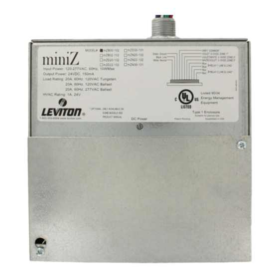
This user's guide applies to the following part numbers:
Model
Number
mZ n2 2-10 2
Network Remote, Dimmed, Two Room, 120V or 277V
Network Remote, Dimmed Version, 2 Zone, 2 Relay,
mZ n2 0-10 2
120V or 277V
Network Remote, Dimmed Version, 3 Zone, 1 Relay,
mZ n3 0-10 1
120V or 277V
mZn2 2-C0 2
Network Remote, Dimmed, Two Room, 347V
Network Remote, Dimmed Version, 2 Zone, 2 Relay,
mZn2 0-C0 2
347V
Network Remote, Dimmed Version, 3 Zone, 1 Relay,
mZn3 0-C0 1
347V
Features between models vary. As such, not all information in this manual
REMOTE NETWORKING ADDENDUM
Daylight Harvesting Made Simple.
Description
applies to all models.
0-10V
Relay
Outputs
Outputs
2
2
2
2
3
1
2
2
2
2
3
1
Revision A 5/2007
Advertisement

Related Manuals for Leviton miniZ mZn20-102


Summary of Contents for Leviton miniZ mZn20-102
- Page 1 REMOTE NETWORKING ADDENDUM Daylight Harvesting Made Simple. This user’s guide applies to the following part numbers: Model Number mZ n2 2-10 2 Network Remote, Dimmed, Two Room, 120V or 277V Network Remote, Dimmed Version, 2 Zone, 2 Relay, mZ n2 0-10 2 120V or 277V Network Remote, Dimmed Version, 3 Zone, 1 Relay, mZ n3 0-10 1...
- Page 2 NOTES...
- Page 3 ESCRIPTION OF APPLICATION & J ABLE IRING ONFIGURATION : Z-MAX C OTES OTES MINI PERATION TABLE OF CONTENTS .…………………………………..…….. 2 …………...………………………..………. 4 UMPERS DIP S – N WITCH ETTINGS ETWORK ……………………………..………... 6 ONFIGURATION ……………………….……………………... 7 ..……..………... 5 Page 1...
-
Page 4: Description Of Application
STEP 1 DESCRIPTION OF APPLICATION ESCRIPTION OF PPLICATION This Addendum is a supplement to the regular miniZ Users’ Guide which is enclosed with every miniZ shipped. The miniZ Users’ Guide covers all non-network installation procedures and settings for the Remote Networking miniZ. - Page 5 The following is an example of a one-line diagram for a typical application. This illustrates how the Remote Networking miniZ is used with a Z-MAX Master Relay Panel. Page 3...
- Page 6 STEP 2 & J ABLE IRING UMPERS Run at least one Cat-3 or Cat-5 8-wire cable to either Modular-Jack (RJ-45). If only one cable is present, jumper JP2 (on left side) should be on both pins (e.g., closed). If two cables are present, jumper JP2 should be open (on one pin only).
- Page 7 WITCH ETTINGS 1 2 4 8 16 32 F 1 2 3 4 5 6 7 8 9 10 Z = ZMSP (must be one for networking) F = see miniZ operation on page 7 1-32 = Add to get slave address relay number is Address x 4-3 3-zone units have only the 1 relay...
- Page 8 STEP 4 NOTES: Z-MAX Configuration Z-MAX C ONFIGURATION Each miniZ is allocated 4 relay numbers and 4 discrete numbers. Given a slave address, the first relay/discrete number is Slave-Address x 4 – 3. In the Dip Switch example, a miniZ is at “Address 12”. The 1 relay/ discrete is 45.
- Page 9 NOTES: miniZ Operation MINI PERATION If DIP switch ‘F’ (#7) is on, all switchbox and occupancy events are sent to the Z-MAX master and not processed by the miniZ. If DIP switch ‘F’ (#7) is off, the miniZ will process the switchbox and occupancy events (including Dim, Bright, and Max from 5-button stations).
- Page 10 Leviton Lighting Management Systems Division Headquarters 20497 SW Teton, Tualatin, Oregon 97062 Customer Service – (800) 736-6682 Facsimile – (503) 404-5600 Technical Support – (800) 959-6004 P/N PK-93453-10-00-0A...
Need help?
Do you have a question about the miniZ mZn20-102 and is the answer not in the manual?
Questions and answers