Table of Contents
Advertisement
Quick Links
Advertisement
Table of Contents

Related Manuals for GMI GDUnet


Summary of Contents for GMI GDUnet
- Page 1 Gas Measurement Instruments Ltd User Handbook...
- Page 2 Issue 4 05/10/2016 Part Number: 14765 GMI welcomes comments on all our publications. Your comments can be of great value in helping us to improve our customer publications. Please send any comments that you have to customerservice@gmiuk.com Copyright © Gas Measurement Instruments Ltd 2013...
-
Page 3: Licence Agreement
A licence for the software may not be shared or used concurrently on different computers. This licence is granted for use on the GMI products and for use on one computer. If you require a second copy you must purchase that from... -
Page 4: Day Limited Warranty
GMI to be free from defects in materials and workmanship for a period of 60 (sixty) days from the date you purchased this product. If you notify GMI within the warranty period of such defects in materials or workmanship, GMI will replace the defective CD or handbook. - Page 5 FOR PERSONAL INJURY DAMAGE. The remedies described above are the exclusive remedies extended to you by GMI for any default, malfunction or failure of the product to conform with this warranty or otherwise for the breach of this warranty or any other warranty, whether expressed or implied.
- Page 6 USER HANDBOOK...
-
Page 7: Copyright
This handbook is an important part of the GDUnet product. Please note the following points: • It should be kept with the GDUnet for the life of the product. • Amendments should be attached to this handbook. •... -
Page 8: Safety Procedures
USER HANDBOOK SAFETY PROCEDURES The instruments which are used on the GDUnet can be used to protect life and property and certain elements may be used in potentially explosive, toxic, and oxygen deficient atmospheres. • Never attempt to calibrate, adjust or repair the product unless you are fully trained, aware of all potential hazards and have been assessed by an authorised body as to your competence. -
Page 9: Table Of Contents
CONTENTS TABLE OF CONTENTS LICENCE AGREEMENT .......... i IMPORTANT - READ CAREFULLY ........i ‘flexiCal net’ & ‘IMS Results Manager’ - SOFTWARE LICENCE ................I 30 DAY LIMITED WARRANTY ..........ii LIMITED WARRANTY ............ii COPYRIGHT ............v LIABILITY ................v MODIFICATION NOTICES..........v DISPOSAL ADVICE ............v SAFETY PROCEDURES ........... - Page 10 3.3.4 Edit Setup / New Template ........3-13 3.3.5 Delete Setup / Template ........... 3-15 3.3.6 Advanced Editor ............3-15 3.3.7 GDUnet Selection ............ 3-16 3.3.8 Test or Calibrate Selection ........3-16 3.3.9 Test / Calibrate Instrument ........3-17 3.4 ADVANCED EDITOR ..........3-19 3.4.1 Edit Gases ..............
- Page 11 CONTENTS 3.4.3 Edit 100% LEL Conversion Factors ......3-23 3.4.4 Edit Purge Time ............3-24 3.5 ADDITIONAL FILE MENU ITEMS ......3-25 3.5.1 File Menu ..............3-25 3.5.2 Edit Menu ..............3-26 3.5.3 Help Menu ..............3-26 3.5.4 GDU Status Check ........... 3-27 3.6 PREFERENCE SETTINGS ........
- Page 12 4.5.1 Results Download .............4-11 4.5.2 Results Processing ..........4-12 4.5.3 GDU List ..............4-13 GDUnet OPERATION ...........5-1 5.1 GDUnet Models ............5-1 5.2 MAIN FEATURES............. 5-2 5.2.1 LCD ................5-3 5.2.2 Test LEDs ..............5-3 5.2.3 External Connectors ........... 5-4 5.2.4 Gas Connections ............
- Page 13 CONTENTS TEST / CALIBRATION SETUP OF GMI PORTABLE INSTRUMENT .............6-1 6.1 CALIBRATE GASURVEYOR 526 INSTRUMENT ..6-1 6.1.1 Start Software ............6-1 6.1.2 Create New Setup Template ........6-3 6.1.3 Send Calibration File ..........6-9 STANDALONE MODE .........7-1 7.1 SEND TEST / CALIBRATION SETUP FILES TO USB ..
- Page 14 USER HANDBOOK...
-
Page 15: Introduction
INTRODUCTION INTRODUCTION 1.1 BASIC CONCEPTS The Gas Delivery Unit (GDUnet) can be used in three different applications: • As a gas delivery unit in an Instrument Management System (IMS) - see paragraph (a). • As a gas delivery unit in a workshop system - see paragraph (b). - Page 16 (b) The GDUnet as a gas delivery unit in a workshop system. A workshop system is used by an instrument technician to service, repair and calibrate / test instruments annually, or more frequently if required.
-
Page 17: Calibration Gases
The GDUnet is connected to cylinders of calibration gas to ensure that a consistent standard can be maintained against which the instrument can be checked. The GDUnet can connect up to 8 gas cylinders (a 4 gas cylinder version is also available). 1.2.1 Recommended Types The instrument should be calibrated in the gas it will be used in, rather than using calibration factors, i.e. -
Page 18: Limits Of Preparation
Methane Instruments with ppm Range 800ppm CH Methane Instruments with CO Range 500ppm CO Methane Instruments with H S Range 50ppm H Note: This list is for guidance only and does not cover all the ranges or gases that GMI instruments will cover. -
Page 19: Calibration Limits
INTRODUCTION 1.2.6 Specification For detailed specifications on test limits and gases users should consult instrument manuals, service bulletins, operating procedures and specifications to ensure that the specifications and limits suit their need and are in line with their Company procedures. The manufacturer or his agent should be consulted for up to date instrument information. -
Page 20: Flexical Net
This allows the user to specify how instruments will be tested or calibrated and includes gases, concentrations and pass or fail criteria. flexiCal net is also used to register additional GDUnet’s to the network. The installation of the software is detailed in Chapter 2. -
Page 21: Flexical Net Installation
flexiCal net INSTALLATION 2.1 SYSTEM REQUIREMENTS To install the flexiCal net software package, you require the following minimum system requirements: • PC / Laptop running Windows XP™ or newer • Processor speed 1GHz • 512Mb RAM • A minimum of 850Mb of free hard disk space •... - Page 22 USER HANDBOOK 2. Insert GDUnet CD-ROM into the appropriate CD drive in your PC / Laptop. The ‘Autoplay’ window should appear, displaying the ‘Open folder to view files’ option, as illustrated in Fig 2-1. Should the CD-ROM not run automatically, select ‘Start’ then ‘Computer’...
- Page 23 INSTALLATION 5. To start installation, select the GMI flexiCal net Setup installer, a security warning as illustrated in Fig. 2-2 may be displayed. Click to continue. Fig. 2-2 Security Warning 6. The setup wizard will be displayed, as illustrated in Fig. 2-3.
- Page 24 USER HANDBOOK 7. To proceed with software installation, select an installation folder. The installer creates the folder destination, C:/Program Files/Gas Measurements Instruments Ltd/flexiCal net/, where the software will be installed, as illustrated in Fig. 2-4. Click to continue. An alternative folder destination can be chosen, if preferred. Fig.
- Page 25 flexiCal net INSTALLATION Fig. 2-5 Confirm Installation 9. On completion of installation, the window illustrated in Fig. 2-6 is displayed. Click to exit the installation. Fig. 2-6 Installation Complete...
- Page 26 USER HANDBOOK 10. The flexiCal net software installation is now complete. The CD-ROM can now be removed from the CD drive. A flexiCal net icon is automatically placed on the flexiCal net PC desktop for easy access to the software.
-
Page 27: Flexical Net Operation
flexiCal net OPERATION To start the flexiCal net software package: Select Start / All Programs / Gas Measurement Instruments Ltd / flexiCal net or, double click on the desktop. flexiCal net The main flexiCal net window, as illustrated in Fig. 3-1 can now be seen. -
Page 28: Navigation
USER HANDBOOK 3.1 NAVIGATION From this window, it is possible to navigate through the main functions required to setup any GDUnet to test / calibrate an instrument. File Help Setup Templates (drop down list) Launch Certificate Printer Open User Handbook... -
Page 29: Initial Setup
OPERATION 3.2 INITIAL SETUP If using the GDUnet as a gas delivery unit in an IMS, on first use of flexiCal net, the IMS server MUST be setup. The initial setup of the IMS server is required for a GDUnet to... - Page 30 USER HANDBOOK Enter the password then click ‘OK’. Note: The factory set password is ‘default’. The password can be edited as detailed in section 3.6 PREFERENCE SETTINGS. The preferences dialogue window is now displayed, click ‘Select IMS’, as illustrated in Fig. 3-5. Fig.
- Page 31 flexiCal net OPERATION The connections properties window, as illustrated in Fig. 3-6 will now be present: Fig. 3-6 Connection Properties...
-
Page 32: Server Name
USER HANDBOOK 3.2.2 Server Name To setup the server name: Click the drop down arrow from the Server name section and select the appropriate server name to be used, as illustrated in Fig. 3-7. Fig. 3-7 Server Name... -
Page 33: Database Connection
flexiCal net OPERATION 3.2.3 Database Connection To setup a database connection: Click the drop down arrow from the Select or enter a database name section and select or enter the appropriate database connection to be used, as illustrated in Fig. 3-8. Fig. -
Page 34: Calibrate
This function is used to define the gases to be applied to the instrument and then sends the test or calibration setup files to a GDUnet. There is also the option to select which GDUnet the setup files are sent too. -
Page 35: Calibration Setup Editor
/ calibration of the instrument. In this example, gas types and values, for the GDUnet can be viewed / edited. There is also a facility to edit the gas test / calibration limits, conversion factors, purge time, via the ‘Advanced Editor’... - Page 36 Delete Setup Gases Advanced Editor Gas Delivery Unit Display all Gas Types Gas Unit / Value Fig. 3-10 Setup Editor As illustrated in Fig. 3-10, the ‘GDUnet Setup Template’ references ‘GDUnet’ as the hardware required to test / calibrate instruments. 3-10...
-
Page 37: Edit Calibration Option
OPERATION 3.3.3 Edit Calibration Option To view / setup, gas types and values, for the GDUnet, proceed as follows: The ‘GDUnet Setup Template’, using the ‘GDUnet’, includes the following: Gas 1: This is always ‘Zero Air’, used for zeroing the instrument’s ranges. - Page 38 USER HANDBOOK 2. To edit default template, select the ‘CombiGas Settings’ button, as illustrated in Fig. 3-12. CombiGas Settings Fig. 3-12 Select ‘CombiGas Settings’ Fig. 3-13 displays the contents of an example CombiGas template. Fig. 3-13 CombiGas Contents 3. The template gases / values, illustrated in Fig. 3-13, can be compared and must be compatible with the corresponding gases / values on the gas cylinder label.
-
Page 39: Edit Setup / New Template
flexiCal net OPERATION 3.3.4 Edit Setup / New Template To edit template gas type or value proceed as follows: 1. The ‘gas type’ drop down arrow allows selection of an alternative gas to the one displayed in adjacent window, as illustrated in Fig. - Page 40 USER HANDBOOK 3. If the gas value requires editing, highlight current value then type replacement value, as illustrated in Fig. 3-16. Fig. 3-16 Edit Gas Value 4. On completion, select to return to the setup editor window, as illustrated in Fig. 3-10. 5.
-
Page 41: Delete Setup / Template
Advanced Editor settings should not normally be accessed as gases, gas ranges and corresponding limits are factory set and should not require adjustment. GMI cannot be held responsible if these values are edited. This option is password protected and is accessed by selecting ‘Advanced Editor’... -
Page 42: Gdunet Selection
USER HANDBOOK 3.3.7 GDUnet Selection To test or calibrate an instrument, a GDUnet must have the required test or calibration files received via the network. To select a GDUnet registered on the network, in the ‘Send To’ section, click the drop down arrow and select the required GDUnet, as illustrated in Fig. -
Page 43: Test / Calibrate Instrument
3.3.9 Test / Calibrate Instrument In this example, an instrument is the subject of a calibration procedure using the pre-loaded GDUnet Setup Template and GDUnet GMI02010009 - Prototype 009. When you are ready to send the setup across the network,... - Page 44 USER HANDBOOK Fig. 3-22 Generating Tests Following this the GDUnet is cleared prior to the test file being sent, as illustrated in Fig. 3-23. Fig. 3-23 Preparing GDUnet After being cleared the test files are then transferred to the GDUnet, as illustrated in Fig. 3-24.
-
Page 45: Advanced Editor
The Advanced Editor should not normally be accessed as gases, gas ranges and corresponding limits are factory set and should not require adjustment. GMI cannot be held responsible if these values are edited. This option is password protected, and can be accessed by selecting ‘Advanced Editor’... - Page 46 USER HANDBOOK Fig. 3-26 Advanced Editor 2. To view the individual gas ranges, select a gas, e.g. Oxygen, to display the Oxygen gas range, as illustrated in Fig. 3-27. Fig. 3-27 View Gas Ranges 3-20...
-
Page 47: Edit Gases
flexiCal net OPERATION 3.4.1 Edit Gases Apply Gas Application Time Value: (not normally applicable to CombiGas) If, for example, a number of individual gases were listed in the ‘Gases’ window, a specific time value for application of each gas type can be specified. Simply, position cursor in panel adjacent to highlighted gas, then type a value (in seconds). -
Page 48: Edit Gas Limit(S)
USER HANDBOOK Select button to save alternative flammable gas. Delete Range: To delete a gas range from list in the ‘Ranges’ window, highlight the gas range to be removed, e.g. Carbon Monoxide, then select to remove from list. Update Range: to save any ‘Range’... -
Page 49: Edit 100% Lel Conversion Factors
flexiCal net OPERATION Fig. 3-30 Edit High Gas Limit Warning: Care should be taken if editing gas limits. 3. Type new value in editing panel. 4. Select button to store updated value. 3.4.3 Edit 100% LEL Conversion Factors The advanced editor window displays the default 100% LEL conversion factors for Methane, Pentane, Propane and Butane calibration gases, as illustrated in Fig. -
Page 50: Edit Purge Time
USER HANDBOOK Fig. 3-32 Edit Methane Conversion Factor 2. Select button to store updated value, if no further ‘advanced editing’ is required. 3.4.4 Edit Purge Time This feature normally applies to automatic calibration only. 1. To edit the purge time (in seconds), select radio button adjacent to panel displaying time value, as illustrated in Fig. -
Page 51: Additional File Menu Items
flexiCal net OPERATION 3.5 ADDITIONAL FILE MENU ITEMS From the ‘File’, ‘Edit’ and ‘Help’ menus, the user can access additional items, details of which are explained in the following paragraphs: File Help Open User Handbook Launch Certificate Printer Check For Updates Exit flexiCal net Folders Edit... -
Page 52: Edit Menu
Refer to section 3.6 for ‘PREFERENCE SETTINGS’. 3.5.3 Help Menu From the ‘Help’ menu, the following items can be accessed: Open User Handbook: GDUnet This link provides the user with access to the User Handbook. The user handbook can also be accessed in a separate folder in the root directory on software CD-ROM. -
Page 53: Gdu Status Check
OPERATION GDU Status Check: Selecting will check the status of ALL GDUnet devices connected to the network. Status refers to whether a GDUnet is: Online - connected to the network, or Offline - not connected to the network. - Page 54 IP Address - Any ONLINE GDUnet will show an assigned IP Address. • Last Synced - this is the last time the GDUnet synchronised with the IMS database. The menu bar, illustrated in Fig. 3-37, provides the user with the...
-
Page 55: Preference Settings
3.6 PREFERENCE SETTINGS The preferences dialogue sets the global conditions for flexiCal net software to setup the IMS server / database, add a GDUnet to the network, enable visible gas ranges, default limits on instrument tests and also gas application times. - Page 56 USER HANDBOOK Enter password then click ‘OK’ button. Note: The factory set password is ‘default’. The password can be edited as detailed later in this chapter. The preferences dialogue box is now displayed. The dialogue box contains two selectable tabs: ‘General’ and ‘Ranges’. General tab is illustrated in Fig.
-
Page 57: General' Tab
flexiCal net OPERATION 3.6.1 ‘General’ Tab To save any preference change then close window, select To reject any preference change and return to factory default settings, select Note: Previously made changes will also be discarded. 3.6.1.1 Cal Due (Gasurveyor 500 series only) Following calibration, the calibration due (Cal Due) date is normally set as one year from present date (i.e. -
Page 58: Purge Time
USER HANDBOOK 3.6.1.4 Purge Time By default, gas purge time is set to 30 seconds. To override this setting, i.e. disable feature, un-tick the ‘Default’ To adjust the Time Value, use arrows. Value can be adjusted from 15 to 120 seconds. 3.6.1.5 Leak Checking During the Test / Calibration process, both instrument pump and gas supply are stopped simultaneously. - Page 59 OPERATION Note: If password is forgotten, contact GMI for recovery details. To change the password, select from the ‘General’ tab in the ‘Preferences’ window. The window illustrated in Fig. 3-41 is displayed: Fig. 3-41 Enter Current Password Enter current password then select ‘OK’ button.
-
Page 60: Reset Settings
, illustrated in Fig. 3-40. 3.6.1.9 Select IMS For a GDUnet to connect and be recognised on the network, each GDUnet has to be registered to the IMS database. To setup the IMS database, select The window illustrated in Fig. - Page 61 OPERATION Fig. 3-44 Connection Properties For the GDUnet to successfully connect to the network, the following MUST be setup correctly: • Server name - this is the database management system which contains the IMS database. • Database connection - this is the IMS database which stores all registered GDUnet’s to the network.
- Page 62 USER HANDBOOK Server Name To setup the server name: Click the drop down arrow from the Server Name section and select the appropriate server name to be used, as illustrated in Fig. 3-45. Fig. 3-45 Server Name 3-36...
- Page 63 flexiCal net OPERATION Database Connection To setup a database connection: Click the drop down arrow from the Select or enter a database name section and select or enter the appropriate database connection to be used, as illustrated in Fig. 3-46. Fig.
-
Page 64: Add Gdu
To register a GDUnet to the IMS database, select The window illustrated in Fig. 3-47 is displayed: Fig. 3-47 Enter GDU Details Enter the serial no. and a description of the GDUnet to be registered to the network, then select to confirm details. -
Page 65: Edit Gdu
To amend the description details of a registered GDUnet, select The window illustrated in Fig. 3-50 is displayed: Fig. 3-50 Edit GDUnet Description Select the serial no. of the GDUnet to amend from the drop down list, amend the description of the GDUnet, then select to confirm. - Page 66 USER HANDBOOK As an example, GDUnet with serial no. ‘000003’ is to have the description amended to ‘Prototype 4’, as illustrated in Fig. 3-51. Fig. 3-51 Example GDUnet Description Change Confirm the amendments are correct, as illustrated in Fig 3-52.
-
Page 67: Ranges' Tab
flexiCal net OPERATION 3.6.2 ‘Ranges’ Tab If the ‘Ranges’ tab is selected from Preferences window, the dialogue box illustrated in Fig. 3-54 is displayed: Fig. 3-54 Preferences - Ranges To save any preference change then close window, select 3.6.2.1 Reset All Range Defaults To reset all gas ranges to factory set defaults, select 3-41... -
Page 68: Zero Air Limit
USER HANDBOOK 3.6.2.2 Zero Air Limit At the start of a Test / Calibration, zero air is applied to each range and will record a ‘Pass’ if the reading is within this amount of zero, or 20.9 for oxygen. To edit ‘Zero Air Limit’ value, highlight existing value in window then type new value. -
Page 69: Ims Results Manager
IMS RESULTS MANAGER 4.1 INTRODUCTION The test results of all instruments that have been tested / calibrated on the GDUnet are stored in the GDUnet internal memory. The internal memory can store approximately 1000 test results. These results are retrieved from the GDUnet and downloaded to the IMS database using the IMS Results Manager software package. -
Page 70: Installation
, Windows Vista or Windows 7 platforms, proceed as follows: 1. Insert GDUnet CD-ROM into the appropriate CD drive in your PC / Laptop. The ‘Autoplay’ window should appear, displaying the ‘Open folder to view files’ option, as illustrated in Fig 4-1. - Page 71 RESULTS MANAGER 2. GMI recommend that before using this software package, the user reads the User Handbook. Adobe Reader must be installed on your PC / Laptop to view the User Handbook. 3. Before installing the IMS Results Manager software package, it is recommended that the user exits all other Windows programs.
- Page 72 Fig. 4-3 Setup Wizard 6. To proceed with software installation, select an installation folder. The installer creates the folder destination, C:\Program Files\GMI\IMS Results Manager\, where the software will be installed, as illustrated in Fig 4-4. Click continue. An alternative folder destination can be chosen, if preferred.
- Page 73 RESULTS MANAGER Fig. 4-4 Installation Folder 7. To confirm and start installation, click , as illustrated in Fig. 4-5. Fig. 4-5 Confirm Installation...
- Page 74 USER HANDBOOK 8. On completion of installation, the window illustrated in Fig. 4-6 is displayed. Click to exit the installation. Fig. 4-6 Installation Complete 9. The IMS Results Manager installation is now complete. The CD-ROM can now be removed from the CD drive. An IMS Results Manager shortcut is automatically IMS Results...
-
Page 75: Setup
For this application to successfully run the following MUST be setup correctly: • Server name - this is the database management system which contains the IMS database. • Database connection - this is the IMS database which stores all the GDUnet test result information. -
Page 76: Server Name
USER HANDBOOK 4.4.1 Server Name To setup the server name: 1. Click to open the connection properties window, as illustrated in Fig. 4-9. Fig. 4-9 Connection Properties... - Page 77 RESULTS MANAGER 2. Click the drop down arrow from the Server Name section and select the appropriate server name to be used, as illustrated in Fig. 4-10. Fig. 4-10 Server Name...
-
Page 78: Database Connection
USER HANDBOOK 4.4.2 Database Connection To setup a database connection: 1. Click to open the connection properties window, as illustrated in Fig. 4-8. 2. Click the drop down arrow from the Select or enter a database name section and select or enter the appropriate database connection to be used, as illustrated in Fig. -
Page 79: Test Result Storage
2. To send the instrument test results to the IMS database (whilst archiving onto a PC). 3. The ability for users to select which GDUnet’s to retrieve results from. 4.5.1 Results Download The IMS Results Manager software connects to GDUnet’s registered on the server;... -
Page 80: Results Processing
USER HANDBOOK 4.5.2 Results Processing The IMS Results Manager looks for any new test files to process; then archives the files onto the PC, whilst, sending the test results to the IMS database. Fig. 4-13 illustrates the ‘Results Processing Progress’ tab and shows the instrument result test files being detected and then archived. -
Page 81: Gdu List
Fig. 4-14 illustrates the ‘GDU List’ tab and shows that all GDU’s are currently active. If a GDUnet is active the results are being retrieved and processed. Results are not retrieved from Ignored GDU’s. - Page 82 GDU to be moved, select the right (or left) directional arrow and the GDU will move to the ignored list (or active list). Fig. 4-15 shows the example of GDUnet ‘GMI02010011’ having been moved to the ignored GDU list. Fig. 4-15 GDUnet Ignored...
-
Page 83: Gdunet Operation
GDUnet OPERATION GDUnet OPERATION 5.1 GDUnet Models There are eight (8) models of GDUnet, as follows: Part No. Gas Connections Fittings Keypad 14750 14750Q 1/4 inch 14751 14751Q 1/4 inch 14780 14780Q 1/4 inch 14781 14781Q 1/4 inch The differences between the models are: •... -
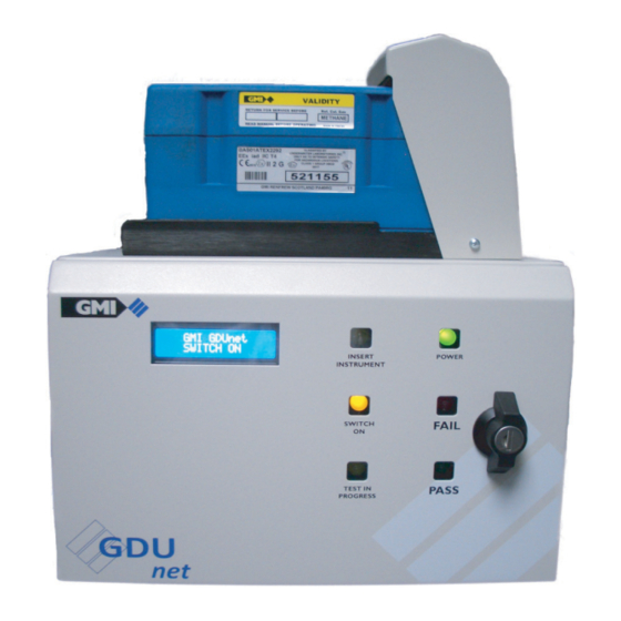
Page 84: Main Features
USER HANDBOOK 5.2 MAIN FEATURES The main features of the GDUnet are illustrated in Fig. 5-1 and described as follows: Fig. 5-1 Main Features 1. Gas Connections 6. Test LED’s 2. Communications 7. Keypad (optional) 3. Microswitches 8. External Connectors 4. -
Page 85: Lcd
Fig. 5-2. GDUnet #010001 INSERT GMI Fig. 5-2 Example of LCD status 5.2.2 Test LEDs The front panel of the GDUnet contains six (6) LEDs relating to the current status of the GDUnet and instrument being tested. Fig. 5-3 Test LEDs... -
Page 86: External Connectors
The connector locations are illustrated in Fig. 5-4. Fig. 5-4 External Connectors 5.2.4 Gas Connections The GDUnet can be fitted with 4 or 8 gas connections. The gases for testing and calibrating instruments are connected to the gas inlet adaptors as shown, in Fig. 5-5, below. -
Page 87: Gas Nozzle
GDUnet Installation Guide, part no. 14766. 5.2.5 Gas Nozzle Gas is delivered to the instruments by the GDUnet via the outlet nozzle. When the instrument is located correctly in the tray the nozzle ‘O’ ring ensures there is a seal between the nozzle and the instrument, therefore no gas leakage. -
Page 88: Microswitches
USER HANDBOOK 5.2.6 Microswitches The GDUnet contains two (2) contact microswitches located inside the instrument hood, as illustrated in Fig. 5-7. The purpose of these microswitches is as follows: MICROSWITCH (1): Detects when an instrument has been correctly located in the tray and activates the ‘Switch ON’ LED on the GDUnet front panel. -
Page 89: Optical Port
GDUnet OPERATION 5.2.7 Optical Port Optical communication occurs when microswitch 2 has been activated. The following examples are types of instruments that use optical communications: • Gasurveyors (except Gasurveyor 700) • First Responders • Leak Surveyor The optical port is illustrated in Fig. 5-8 below. -
Page 90: Irda Window
IrDA COMMUNICATIONS Fig. 5-9 IrDA Window 5.2.9 Front Panel Lock The front panel of the GDUnet can be secured with a key-lock, as illustrated in Fig. 5-10. Two (2) keys are supplied with the unit. Fig. 5-10 Front Panel Lock... -
Page 91: Keypad
GDUnet OPERATION 5.2.10 Keypad The keypad version of the GDUnet will only allow users to test / calibrate an instrument after a user ID has been entered. The user, when prompted, enters an ID code (can be up to 9 digits) followed by the # key. -
Page 92: Standard Operation
2. After approximately 30 seconds the buzzer will sound and the 6 test LEDs will illuminate in sequence. 3. For the keypad version of the GDUnet, the display will show ‘Enter ID then #’, enter the user ID to continue. -
Page 93: Test / Calibration Procedure
2. Ensure flexiCal net software installation has taken place, refer to chapter 2 - flexiCal net Installation. 3. Send the required test / calibration files to the GDUnet, refer to chapter 3 - flexiCal net Operation. If using the GDUnet in standalone mode refer to chapter 7 - Standalone Mode. - Page 94 USER HANDBOOK GDUnet Quick Operation Guide GDUnet #010001 GDUnet #010001 INSERT GMI INSERT GMI GDUnet #010001 GDUnet #010001 SWITCH ON SWITCH ON TEST IN GAS ON: WARMING UP PROGRESS ALL TESTS PASS ALL TESTS PASS REMOVE GMI REMOVE GMI FAILED TEST REMOVE GMI www.gmiuk.com...
- Page 95 INSERT GMI GDUnet #010001 GDUnet #010001 SWITCH ON SWITCH ON TEST IN GAS ON: WARMING UP PROGRESS ALL TESTS PASS ALL TESTS PASS REMOVE GMI REMOVE GMI FAILED TEST REMOVE GMI Fig. 5-13 GDUnet with Keypad - Quick Operation Guide 5-13...
- Page 96 USER HANDBOOK 5-14...
-
Page 97: Test / Calibration Setup Of Gmi Portable Instrument
To perform calibration, the calibration file for the instrument must be sent to a GDUnet. To setup the Gasurveyor 526 calibration file, ensure flexiCal net has been installed and the GDUnet has been registered on the IMS server. Refer to chapters 2 and 3 for details. 6.1.1 Start Software... - Page 98 USER HANDBOOK Fig. 6-1 Main Window Select the drop down menu arrow, illustrated in Fig. 6-2, to view stored setup templates. Fig. 6-2 View Setup Template(s) If there is an existing template in the drop down menu for the Gasurveyor 526 instrument, select template. The calibration gas setup can be viewed / verified in ‘Setup Editor’...
-
Page 99: Create New Setup Template
TEST / CALIBRATION EXAMPLE 6.1.2 Create New Setup Template 1. Select the Setup Editor button. The window illustrated in Fig . 6-3 is displayed. Fig. 6-3 Setup Editor 2. Select ‘New Setup’ button from the ‘Setup Editor’ window. The window illustrated in Fig 6.4 is displayed: Fig. - Page 100 USER HANDBOOK 3. Select the drop down menu arrow, illustrated in Fig. 6-5, to display the GDUnet as the calibration station and gas delivery unit suitable for all GMI instrument types: Fig. 6-5 Select Rig 4. The gases can now be specified. A total of seven gases can be loaded (Nos.
- Page 101 TEST / CALIBRATION EXAMPLE Fig. 6-6 Specify Gas Type 6. From drop down list, select ‘Methane’. PPM, LEL and VOL options are then displayed, as illustrated in Fig. 6-7. Fig. 6-7 Specify Gas Range...
- Page 102 USER HANDBOOK 7. From list illustrated in Fig. 6-7, select ‘PPM’. The displayed ‘value’ window automatically selects ‘PPM’ as the unit of measure. 8. The value on the gas cylinder label in this example is 800 PPM. To enter this (800) value, highlight existing (0) value then type new value in window, as illustrated in Fig.
- Page 103 TEST / CALIBRATION EXAMPLE Fig. 6-9 Setup Continuation 11. Depending on supplied cylinder gas concentration, a corresponding value should be entered in ‘%’ window. The value on the gas cylinder label in this example is 50%. To enter this (50) value, highlight existing (0) value then type new value in window.
- Page 104 Note: There is an ‘Advanced Editor’ feature available, as detailed in Chapter 3, section 3.4. This feature should not normally be accessed as gases, gas ranges and corresponding limits are factory set and should not require adjustment. GMI cannot be held responsible if these values are edited.
-
Page 105: Send Calibration File
Fig. 6-11 Fig. 6-11 Select Setup 2. In this example ‘Calibrate ’ and GDUnet ‘GMI02000003 - Prototype 3’ are selected from the ‘Send To’ section. 3. When you are ready to send the ‘Gsv 526’ calibration file to GDUnet ‘GMI02000003 - Prototype 3’, select... - Page 106 USER HANDBOOK 6-10...
-
Page 107: Standalone Mode
STANDALONE MODE The GDUnet can be setup to operate in standalone mode. This requires the flexiCal net test and calibration setup files to be uploaded to the GDUnet via a USB memory stick. 7.1 SEND TEST / CALIBRATION SETUP FILES TO USB 1. - Page 108 USER HANDBOOK Next, select , as illustrated in Fig. 7-2. Fig. 7-2 Send Setup Files The ‘Select USB Drive...’ window will open. Highlight the USB memory stick, the setup files are to be sent to, and select , as illustrated in Fig. 7-3. Fig.
- Page 109 STANDALONE MODE Test and calibration setup files are now generated and transferred to the USB memory stick, as illustrated in Fig. 7-4. Fig. 7-4 File Transfer in Progress On completion the ‘Transfer Complete!’ window will open, select to continue, as illustrated in Fig. 7-5. Fig.
-
Page 110: Upload Test / Calibration Setup Files To Gdunet
7.2 UPLOAD TEST / CALIBRATION SETUP FILES TO GDUnet Ensure the GDUnet is powered on and the start up sequence is complete. Unlock the front panel door and insert the USB memory stick into the USB port as illustrated in Fig. 7-6. -
Page 111: Download Test Results
GDUnet are stored in the internal memory. To download the test results from the GDUnet, ensure the GDUnet is powered on and the start up sequence is complete. Unlock the front panel door and insert a USB memory stick into the USB port as illustrated in Fig. -
Page 112: Certificate Generation
USER HANDBOOK 7.4.1 Certificate Generation Certificates of the Test Results can be generated by following the process below: 1. Select ‘Launch Certificate Printer’ from the file menu options, as illustrated in Fig. 7-8. Fig. 7-8 Launch Certificate Printer 2. The certificate printer window will open, as illustrated in Fig. 7-9. - Page 113 STANDALONE MODE 3. The window contents can now be completed to include company name, address, etc., as illustrated in Fig. 7-10. Fig. 7-10 Certificate Printer Window When the Certificate Printer window is complete, select the ‘Create Certificate’ button, as illustrated in Fig. 7-10.
- Page 114 USER HANDBOOK 4. After selecting the ‘Create Certificate’ button, a folder will be displayed, locate the test results folder, highlight a test result for certificate generation then select Fig. 7-11 shows an example of a highlighted test result. Fig. 7-11 Select Test Result for Certificate Generation 5.
- Page 115 STANDALONE MODE Fig. 7-13 Calibration Certificate...
-
Page 116: Certificate Files
USER HANDBOOK 7.4.2 Certificate Files Generated certificate files can be accessed by selecting ‘Certificates’ from the ‘Help / flexiCal net Folders’ menu options, as illustrated in Fig. 7-14. Fig. 7-14 View Certificates A folder will be displayed, showing generated certificate files, identifying the date and time of each certificates generation. -
Page 117: Index
Calibration Setup Options Edit Gas Type 3-13 CD-ROM Options Edit Gas Value 3-14 Certificate Generation Edit GDU 3-39 Certificate Printer Window Edit GDUnet Description 3-39 Check For Updates 3-26 Edit Menu 3-26 CombiGas 3-11 Edit Purge Time 3-24 CombiGas Settings... - Page 118 IrDA Window Gas Application Accuracy 3-42 Key-lock Gas Application Time 3-42 Keypad Gas Connections 5-1, 5-4 Keypad Entry Gas Delivery Unit (GDUnet) 1-1 Gas inlet adaptors Gas Limit 3-42 Last Synced 3-28 Gas Limits Launch Certificate Printer Gas Nozzle GDU List...
- Page 119 INDEX Microswitches Results Download 4-11 MODIFICATION NOTICES Results Processing 4-12, 4-13 Retrieve instrument test results 4-11 Name Template NAVIGATION SAFETY PROCEDURES Network communication Select GDU Status Check 3-27 New Setup Select IMS 3-3, 3-34 New Template 3-14 Select Preferences 3-3, 3-29 Select Rig Select ‘Save to...’...
- Page 120 TEST RESULT STORAGE 4-11 Time, Purge 3-24 Update Range 3-22 Updates 3-26 UPLOAD TEST / CALIBRATION SETUP FILES TO GDUnet 1-2, 5-4 USB memory stick 7-1, 7-4, 7-5 View Certificates 7-10 View Gas Ranges 3-20 VIEW / PRINT TEST RESULTS...
- Page 122 Head Office Inchinnan Business Park Renfrew Scotland PA4 9RG Tel: +44 (0)141 812 3211 Fax: +44 (0)141 812 7820 sales@gmiuk.com www.gmiuk.com Service & Calibration Centre 25 Cochran Close Crownhill Milton Keynes MK8 0AJ Tel: +44 (0)1908 568 867 Fax: +44 (0)1908 261 056 service@gmiuk.com...
Need help?
Do you have a question about the GDUnet and is the answer not in the manual?
Questions and answers