Table of Contents
Advertisement
Available languages
Available languages
Quick Links
Advertisement
Table of Contents

Related Manuals for GMI V!SA


Summary of Contents for GMI V!SA
- Page 1 V!SA (4-Gas Version) User Handbook...
- Page 2 Issue 6 07/08/2013 Part Number: 66094 GMI welcomes comments on all our publications. Your comments can be of great value in helping us to improve our customer publications. Please send any comments that you have to our Sales Department at GMI. Contact details are provided inside the back cover of this handbook.
- Page 3 COPYRIGHT This User Handbook is copyright of Gas Measurement Instruments Ltd (GMI) and the information contained within is for use only with the GMI V!SA. Reproduction, in whole or in part, including utilisation in machines capable of reproduction or retrieval without written permission of Gas Measurement Instruments Ltd.
- Page 4 94/9/EC 94/9/EC Any right of claim relating to product liability or consequential damage to any third party against GMI is removed if the above warnings are not observed. AREAS OF USE AREAS OF USE Exposure to certain chemicals can result in a loss of sensitivity of the flammable sensor.
- Page 5 DECLARATION OF CONFORMITY Refer to current Declaration of Conformity document Part No. 66250 (supplied with product)
- Page 6 V!SA - USER HANDBOOK...
- Page 7 REVISION RECORD Date Issue Description Of Change 06/06/2003 06/06/2003 New User Handbook. 12/01/2004 12/01/2004 Revised to include effect of CN 2435, CN 2443, CN 2459, CN 2493, CN 2494, CN 2496, CN 2544 and CN 4014. 12/06/2006 12/06/2006 Revised to include translations update and effect of CN 4099, CN 4137, CN 4146, CN 4178, CN 4224 and CN 4226.
- Page 8 V!SA - USER HANDBOOK 07/08/2013 Revised to include effect of CN 6280.
- Page 9 CONTENTS TABLE OF CONTENTS COPYRIGHT LIABILITY MODIFICATION NOTICES SOFTWARE DISPOSAL ADVICE SAFETY AREAS OF USE STORAGE, HANDLING AND TRANSIT WARRANTY DECLARATION OF CONFORMITY REVISION RECORD...
-
Page 10: Table Of Contents
V!SA - USER HANDBOOK INTRODUCTION 1.1 GENERAL DESCRIPTION 1.2 FEATURES 1.3 DATA LOGGING 1.3.1 Viewing Data Logged Readings 1.4 HYDROPHOBIC TYPE FILTER(S) 1.5 CONSTRUCTION 1.6 IDENTIFICATION LABEL 1.7 PHYSICAL PROPERTIES 1.7.1 Environment 1.7.2 Typical Flow Rate Information 1.7.3 Warm-up / Stabilization Time 1.7.4 Response Time (T90) - Page 11 CONTENTS 2.2.2 Battery Status 2.2.3 Time and Date 2.2.4 Calibration Due Date 2.2.5 Select Calibration Gas 2.2.6 Sensor Confirmation Check 2.2.7 Normal Operating Display 2.3 SWITCHING THE DISPLAY BACKLIGHT ON / OFF 2-10 2.4 VIEWING THE MAXIMUM AND MINIMUM RECORDED VALUES SINCE SWITCH ON 2-10 2.5 ALARMS RESET OR ACKNOWLEDGE 2-13...
- Page 12 V!SA - USER HANDBOOK 3.1.4 Toxic Alarm Limits 3.2 ACKNOWLEDGE GAS ALARMS 3.3 HIGH FLAMMABLE GAS OVER-RANGE ALARM 3.4 FAULT ALARMS 3.4.1 Low Battery 3.4.2 Zero Fault 3.4.3 Zero Fault - Only applicable to instruments with CO2 sensor fitted 3-10 3.4.4 Sensor Fault...
- Page 13 CONTENTS 4.3 BATTERY PACKS 4.3.1 Removing and Replacing a Battery Pack 4-10 4.3.2 Charging (Rechargeable) Battery Packs 4-12 4.3.3 Replacing Alkaline Batteries 4-17 CALIBRATION 5.1 GENERAL DESCRIPTION 5.2 CALIBRATION VALIDITY ACCESSORIES ADDITIONAL INFORMATION 7.1 TRAINING 7.2 WORLD WIDE WEB OPERATING INSTRUCTIONS...
- Page 14 V!SA - USER HANDBOOK INDEX...
-
Page 15: Introduction
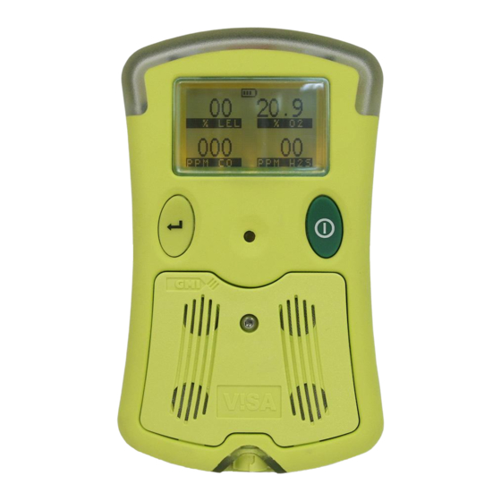
Small and lightweight, it is suitably certified to recognised International Standards. Fig. 1.1 V!SA Instrument The V!SA is used for confined space monitoring, for example, in sewers, underground piping or within tanks, and other personal monitoring applications. Its high intensity audible and bright visual alarms provide early warning of dangerous gas levels. - Page 16 V!SA - USER HANDBOOK The instrument is operated via a single push button, providing the user with a simple to use gas detector. From one (1) up to four (4) gases can be monitored from the following list: Note: A five (5) gas version is also available. For details, contact GMI Ltd.
-
Page 17: Features
These options are detailed in italic text, where applicable, and are also detailed in the ‘CONFIGURATION HANDBOOK’. 1.2 FEATURES The main features of the V!SA instrument are: • Integral impact resistant housing. •... - Page 18 V!SA - USER HANDBOOK • Instrument sealed to IP65 and sensing elements, sample inlet and charging socket sealed to IP54, making the instrument suitable for outdoor use • A comprehensive range of accessories. > > > > > > >...
-
Page 19: Data Logging
1.3.1 Viewing Data Logged Readings Data logged readings can be downloaded from the instrument into a PC using GMI software and communication adaptor. Contact our Sales Department at GMI for further details. 1.4 HYDROPHOBIC TYPE FILTER(S) -
Page 20: Construction
V!SA - USER HANDBOOK 1.5 CONSTRUCTION The instrument is housed in a tough, impact resistant moulded case. The instrument is sealed to IP65 and the sensing elements, sample inlet and charging socket sealed to IP54. The instrument withstands physical impact testing to EN 61779. -
Page 21: Certification
INTRODUCTION 1.8 CERTIFICATION The V!SA instrument is certified as follows: Note: Check instrument labels for actual certification. ATEX II 1 G EEx ia IIB T3 ATEX II 2 G EEx ia d IIC T3 ATEX II 2 G EEx ia d IIC T4 1.8.1 Identification of Symbols... -
Page 22: Performance
V!SA - USER HANDBOOK Sira 05 ATEX 2295 EEx ia d IIC T3 EEx ia d IIC T4 0038/YY Marine Equipment Directive (Module B&E) (European mark of Conformity) 1.8.2 Performance This apparatus conforms to standard EN 50104. Complies with: EN 61779 (Flammable) - Page 23 WARNING Replace battery pack only with GMI Part No. 66056 ; 66210 or 66335. WARNING To reduce the risk of explosion, do not mix new batteries with used batteries, or mix batteries from different manufacturers. These conditions apply to UL approved product...
- Page 24 V!SA - USER HANDBOOK 1-10...
-
Page 25: Operation
Each time you use the instrument carry out the following procedure: Caution: The GMI V!SA can be supplied with a flammable gas sensor. This sensor is designed for use in concentrations of gas not exceeding the Lower Explosive Limit (LEL). -
Page 26: Switching The Instrument On
Switch the instrument off, in fresh air, after use. 2.2 SWITCHING THE INSTRUMENT ON Press and hold the green Right Hand (RH) button one second to switch the instrument on. DISPLAY GREEN (RH) BUTTON YELLOW (LH) BUTTON Fig. 2.1 V!SA Button Operation... -
Page 27: Instrument Identification
Fig. 2.2: Fig. 2.2 Instrument Identification Note: The instrument configuration may not include datalogging, if required, it can be retrofitted by GMI at a later date. Contact GMI Ltd. for details. 2.2.2 Battery Status Provides the user with the Battery charge level, as shown in previous display. -
Page 28: Time And Date
V!SA - USER HANDBOOK 2.2.3 Time and Date The time and date from the instrument’s built-in clock is displayed on the screen during warm-up, as shown in Fig. 2.3. Fig. 2.3 Time and Date If datalogging is being used, the time and date is set from this clock. - Page 29 OPERATION If the Calibration Due Date has expired, the audible and visual alarm activates and the screen, as shown in Fig. 2.5, is displayed during warm-up: Fig. 2.5 Calibration Expired Press and hold the green (RH) button once, to acknowledge the calibration due date is overdue, cancel the audible / visual alarm, and continue to the next display.
-
Page 30: Select Calibration Gas
V!SA - USER HANDBOOK 2.2.5 Select Calibration Gas This configurable option is available to allow the user to select a different flammable gas from that which was originally used to calibrate the instrument. This action allows the instrument software to compensate and thus display more accurate readings when detecting the re-selected gas type. -
Page 31: Sensor Confirmation Check
OPERATION 2.2.6 Sensor Confirmation Check The symbol ◆ appears above each sensor type to confirm that the sensor has been recognised, is working correctly, and is being zeroed. When sensors are zeroed correctly, a symbol ✔ appears above each sensor. Refer to Fig. - Page 32 V!SA - USER HANDBOOK Fig. 2.8 Failed Sensor To acknowledge the alarm, press the green (RH) button once. This will clear the audible / visual alarm and display a flashing spanner symbol, *alternating with the faulty sensor zero reading (*LEL sensor only). An example is shown in Fig 2.9:...
-
Page 33: Normal Operating Display
OPERATION A configurable option is available to force the user to switch the instrument off if a zero fault is detected, as shown in Fig. 2.10: Fig. 2.10 Switch OFF Note: If a sensor fault is detected during normal operation of the instrument, an audible / visual alarm is activated immediately and a spanner symbol is shown adjacent to the faulty sensor type in the display. -
Page 34: Switching The Display Backlight On / Off
V!SA - USER HANDBOOK Each gas the instrument can measure is shown in the display. In the previous example, the instrument is a four gas model that can measure LEL, Oxygen (O ), Hydrogen Sulphide (H S) and Carbon Monoxide (CO). - Page 35 OPERATION Fig. 2.12 Normal Operating Display Press the green (RH) button again, while the screen light is on, to view the maximum gas values stored in the instrument. The example shown in Fig. 2.13 illustrates the maximum gas values stored in a four gas instrument: LEL, Oxygen ), Hydrogen Sulphide (H S) and Carbon Monoxide (CO).
- Page 36 V!SA - USER HANDBOOK The following example, Fig. 2.14, illustrates the minimum gas values stored in a four gas instrument: LEL, Oxygen (O ), Hydrogen Sulphide (H S) and Carbon Monoxide (CO). Fig. 2.14 Minimum Gas Values After these readings have been noted, they can be...
-
Page 37: Alarms Reset Or Acknowledge
OPERATION Note: The maximum and minimum values are cleared from the instrument’s memory when you press and hold the green (RH) button in non-alarm state. The display returns to the normal operating display if no button is pressed. 2.5 ALARMS RESET OR ACKNOWLEDGE When the instrument detects an alarm set point has been reached, the audible and visual alarm will be activated to alert the user. - Page 38 V!SA - USER HANDBOOK c t i c t i c t i c t i c t i c t i c t i t l u c t i t l u c t i t l u...
-
Page 39: Confidence Signal
OPERATION 2.5.1 Confidence Signal During normal operation, the instrument sounds a confidence beep and illuminates the green LED’s briefly every 15 seconds. This function is programmable in the instrument setup software. This function makes the user aware that the instrument is operating correctly: Note: The confidence beep and/or LED’s can be disabled. -
Page 40: Remote Sampling (With Pump Option)
V!SA - USER HANDBOOK 2.7 REMOTE SAMPLING (with pump option) Warning (Hand Aspirator): The V!SA is primarily designed to be used with a built-in pump for remote sampling. The hand aspirator can be used for indicative sampling, but it must be noted that when using a hand aspirator, a reading error in the region of + 20% is possible. -
Page 41: Assisted Diffusion Option
(RH) button re-sets the pump to run at low speed. * Note: GMI strongly recommend that pumped instruments, configured with reactive gases, use assisted diffusion mode in preference to diffusion mode. Note: It is only possible to switch the pump ON / OFF when instrument alarms are inactive. - Page 42 V!SA - USER HANDBOOK 2-18...
-
Page 43: Alarms
ALARMS 3.1 GAS ALARMS Gas alarms are enabled when the instrument is switched Note: Alarms are disabled during warm-up. All gas ranges have alarm limits that trigger the alarm if the measured gas value exceeds the set level. If a preset alarm level is exceeded, the audible alarm sounds, the LED’s flash RED and the gas range in alarm flashes on the display. -
Page 44: Oxygen (O2) Alarm Limits
V!SA - USER HANDBOOK 3.1.3 Oxygen (O ) Alarm Limits Up to one (1) upper and two (2) lower alarm limits are programmable, each with different pitch and tone. All alarms are user configurable to meet the specific needs of different companies. - Page 45 ALARMS changed, if required, via the instrument set up software, or as detailed in the ‘CONFIGURATION HANDBOOK’. In the following two examples, Fig. 3.1 shows a four-gas instrument signalling a ‘Lo Lo’ Oxygen alarm and Fig. 3.2 shows a four-gas instrument signalling a ‘Hi Hi’ LEL alarm. If more than one gas alarm level is exceeded, the gas value will flash for each gas type in alarm.
- Page 46 V!SA - USER HANDBOOK Fig. 3.2 ‘HiHi’ Alarm Each alarm can be latching or non-latching. Latching alarms must be cleared by the user when the gas level returns to within the preset alarm limits. Non-latching alarms clear automatically when the gas level returns to within the preset alarm limits.
-
Page 47: Acknowledge Gas Alarms
ALARMS 3.2 ACKNOWLEDGE GAS ALARMS Caution: Never remove the battery to silence / mute an alarm as this can damage the instrument. Once in a safe gas free area, or the gas reading has returned within the preset limits, press and hold the green (RH) button to silence / mute the alarm sounder and extinguish the gas LED’s. -
Page 48: High Flammable Gas Over-Range Alarm
V!SA - USER HANDBOOK 3.3 HIGH FLAMMABLE GAS OVER-RANGE ALARM Caution: Exposing the LEL sensor to concentrations of flammable gas above 100% LEL can damage the sensor. In order to protect the user from danger in the event of the... - Page 49 ALARMS Switch off by a press and hold of both buttons together. A count timer, from 10 seconds to zero, will appear on the display together with the message ‘GET OUT’ alternating with ‘HIGH GAS’, as shown in Fig. 3.4: then and so on, alternating until zero is reached Fig.
-
Page 50: Fault Alarms
V!SA - USER HANDBOOK 3.4 FAULT ALARMS Refer to Alarms Table, on page 2-14 of this handbook, to identify the audible / visual indication for any of the following faults. 3.4.1 Low Battery The “LOW BATTERY” flag is displayed, intermittently on the screen, when the instrument’s battery power is low (i.e. - Page 51 ALARMS The audible alarm sounds, once every two seconds, and the Red LED’s flash. It is strongly recommended the instrument is returned to a gas free area. Switch the instrument off and then switch on again in clean air. If the fault persists, return the instrument for service.
-
Page 52: Zero Fault - Only Applicable To Instruments With Co2 Sensor Fitted
V!SA - USER HANDBOOK Note: The flashing spanner symbol will only alternate with the faulty sensor reading in the LEL range. If this occurs, the instructions in section 3.4.4 ‘Sensor Fault’, paragraphs (2) and (3), should be followed . 3.4.3 Zero Fault - Only applicable to instruments... - Page 53 ALARMS Note: If a “ZERO FAULT” flag is displayed together with a flashing spanner symbol on any of the other sensors, follow instructions detailed in paragraph 3.4.2. The faulty CO2 sensor will cause the instrument to display a flashing ‘ZERO FAULT’ flag alternating with a gas value to warn the user that this sensor is not correctly zeroed, as shown in Fig.
-
Page 54: Sensor Fault
V!SA - USER HANDBOOK 3.4.4 Sensor Fault There are three types of sensor fault as illustrated in the following displays: 1) If a “ZERO FAULT” flag and a spanner symbol appears above gas type, as shown in Fig. 3.8, then the sensor requires replacement or an electrical fault exists. - Page 55 ALARMS Fig. 3.9 Check Fault 3) If a “ZERO FAULT” flag and a flashing spanner symbol appear, alternating with an LEL gas value as shown in Fig. 3.10, leave instrument on for 30 to 60 minutes then switch instrument Off and On again. If fault remains, return instrument to an approved Service / Repair facility.
-
Page 56: Sample Fault (Pumped Instruments Only)
V!SA - USER HANDBOOK 3.4.5 Sample Fault (Pumped Instruments Only) If the pump symbol changes to the symbol shown in Fig. 3.11, a “FLOW FAULT” flag is displayed and an audible alarm and Red LED’s are activated, then a sample fault or flow fail exists. -
Page 57: Calibration Expired
Check maximum sample line length (30 metres) is not exceeded, check sample filter or probe for blockage, if applicable. 3.4.7 Calibration Expired During normal operation of the instrument where the calibration date has expired, a “CAL EXPIRED” warning flag will flash on the display every 30 seconds to alert the user of the fact that the expiry date has been exceeded. - Page 58 V!SA - USER HANDBOOK The instrument must be switched off immediately. Follow appropriate action required by your company for calibration. 3-16...
-
Page 59: Operator Maintenance
The outer, impact resistant, rubber casing of the V!SA instrument may be cleaned using a non-abrasive moist cloth. Rub the cloth over the outer casing to remove any dirt and grime. -
Page 60: Sensor Grille Filter
V!SA - USER HANDBOOK 4.2.1 Sensor Grille Filter Unscrew the cover screw, in a counter clockwise direction, using the Battery / Sensor Grille Key (Part No. 66166), then remove the cover by sliding it away from the instrument and up towards the display screen. - Page 61 OPERATOR MAINTENANCE Fig. 4.2 Filter and Cover Removed Fit a new Sensor Grille Filter (Part No. 66083), if required. Note: The filter is keyed and therefore can only be fitted in one direction. Replace the sensor cover assembly by first positioning the location feet, then pressing the cover down on to the filter.
- Page 62 V!SA - USER HANDBOOK 4.2.2 Sample Inlet Filter Unscrew the two (2) retaining screws, in a counter clockwise direction, using the Inlet Filter Key (Part No. 66165), then remove the sample line connector. Fig. 4.3 Key in Connector Retaining Screw Push the sample inlet filter disc out by inserting the hexagonal key into the sample nozzle.
- Page 63 OPERATOR MAINTENANCE Fig. 4.4 Filter and Connector Removed...
- Page 64 V!SA - USER HANDBOOK 4.2.3 In-line Hydrophobic Filter (Accessory) The in-line hydrophobic filter assembly consists of the filter and a luer fitting on one side of the filter and a slide- on connection on the other, and is available as an accessory (Part No.
- Page 65 OPERATOR MAINTENANCE Note: If re-fitting the same filter, make sure that filter direction of flow orientation is maintained. This can be easily identified by position of yellow label on filter, i.e. facing instrument. Fit a new In-line Hydrophobic Filter (Part No. 66484). Note that the filter should be fitted with the yellow label facing the instrument.
- Page 66 V!SA - USER HANDBOOK 4.3 BATTERY PACKS Battery packs provide the instrument with the power it requires to operate. Three types of battery pack are available: Long Duration, Fast Charge, and Alkaline. Each type of pack provides a different operational lifetime.
- Page 67 The instrument will then switch Off automatically. The ‘Long Duration’ battery pack can be charged using the following GMI chargers: Standard Charger: The battery pack can be removed from the instrument then connected to the standard charger or, it can be charged while fitted to the instrument.
- Page 68 V!SA - USER HANDBOOK 4.3.1 Removing and Replacing a Battery Pack CAUTION 1) Always switch the instrument off before removing the battery pack. 2) Always replace the protective cap in the Long Duration battery pack charging socket before use WARNING 1) Rechargeable battery pack must be recharged and replaced in a non-hazardous area.
- Page 69 OPERATOR MAINTENANCE Note: Long Duration battery pack is fitted with a captive screw and protective cap. Pull the battery pack down from the instrument to disconnect, as shown in Fig. 4.7. Fig. 4.7 Battery Pack Removed 3a) RECHARGEABLE: Replace with a fully charged battery pack. Refer to ‘Charging (Rechargeable) Battery Pack’, in section 4.3.2.
- Page 70 V!SA - USER HANDBOOK Tighten the captive screw, in a clockwise direction, using the Battery / Sensor Grille Key (Part No. 66166). Note: Care must be taken not to overtighten the captive screw. Fit the protective cap in the Long Duration battery pack charging socket before use.
- Page 71 OPERATOR MAINTENANCE while fitted to the instrument, as shown in Fig. 4.8. It is important that the instrument is switched off when charging a battery pack fitted to the instrument. If the battery pack is fitted to the instrument during charging, the outer two red instrument LED’s illuminate for a period of 14 hours, after which time are replaced by the green LED’s...
- Page 72 If the battery pack is fitted to the instrument during charging, a small battery symbol on the V!SA screen will display charging operation as a flashing bar graph, also, the outer two red instrument LED’s illuminate for a period...
- Page 73 OPERATOR MAINTENANCE of 14 hours, after which time are replaced by the green LED’s Note: This is a timer function only, and does not indicate charged condition of battery pack. Fast Charger The ‘Fast Charge’ or ‘Long Duration’ battery pack can be removed from the instrument and located in the Fast Charger as illustrated below.
- Page 74 V!SA - USER HANDBOOK A green LED on the front of the charger indicates ‘charging in progress’. This LED is extinguished when charging is complete. 10-Way Fast Charger with (up to 9) Slave Unit(s) The ‘Fast Charge’ or ‘Long Duration’ battery pack can be removed from the instrument and located in the Fast Charger master or slave unit.
- Page 75 4.3.3 Replacing Alkaline Batteries CAUTION: To be in compliance with the certification regulations of this product, use only alkaline batteries from the following manufacturers: - Energizer / Energizer Industrial - Panasonic - Sony. WARNING: When replacing batteries in the alkaline battery pack, make sure that you are in a safe area and the instrument is switched Off.
- Page 76 V!SA - USER HANDBOOK Fig. 4.12 Key in Cover Plate Retaining Screw • Replace the three LR6 (AA) size batteries, as shown in Fig. 4.13. Fig. 4.13 Alkaline Batteries Removed 4-18...
- Page 77 Note: Always use three new LR6 (AA) size batteries. Do not mix old and new batteries. • Make sure that the batteries are replaced using correct polarity for + and - • Replace the battery cover plate then tighten the retaining screw in a clockwise direction using the Battery / Sensor Grille Key (Part No.66166).
- Page 78 V!SA - USER HANDBOOK 4-20...
- Page 79 5.1 GENERAL DESCRIPTION The instrument has been calibrated for particular gases. Where any doubt exists the product should be returned to GMI or an authorised distributor for calibration. WARNING: The instrument must be calibrated and configured by authorised personnel only.
- Page 80 12 month period can be expected. This is no guarantee, however, as the precise application of the product is unknown to GMI. Individual codes of practice may dictate shorter periods. Regular checking establishes a pattern of reliability and enables the calibration check period to be modified in line with operational experience.
- Page 81 ACCESSORIES Accessories available for V!SA instrument Std. Accessories Part Number Description 66123 Hand Aspirator (can be used for non-reactive gases only) 66478 Hand Aspirator (c/w 3.0 metres Tygon Tubing) 66118 Sample Line (per metre) 66112 Sample Line Extender (to connect sample lines together) 66136 3.0 metres Tygon Tubing...
-
Page 82: Sample Inlet Filter
V!SA - USER HANDBOOK Part Number Description 66166 Battery / Sensor Grille Key (2mm. A/F) 66167 Instrument Key 66083 Sensor Hydrophobic Filter 66084 Sample Inlet Filter 66210 Alkaline (Drycell) Battery Pack 66056 Long Duration Rechargeable (NiMH) Battery Pack 66335 Fast Charge Rechargeable... - Page 83 ACCESSORIES 66510 Fast Charger c/w Data Download Communications Pack 66511 Fast Charger c/w Set-up Communications Pack Communication Options Part Number Description 66208 Data Downloading Package c/w CD-ROM, Communications Adaptor & User Instructions 66300 Data Downloading Package c/w Charger (Universal Plug) 66445 V!SACAL (Calibration) Package c/w CD-ROM, Communications...
- Page 84 V!SA - USER HANDBOOK...
- Page 85 ADDITIONAL INFORMATION 7.1 TRAINING Training courses are available on all GMI products. Contact GMI Marketing Department for further details: Tel: +44 (0) 141 812 3211 Fax: +44 (0) 141 812 7820 e-mail: sales@gmiuk.com 7.2 WORLD WIDE WEB Visit GMI web site at...
- Page 86 V!SA - USER HANDBOOK...
- Page 87 OPERATING INSTRUCTIONS The following multi-language instructions provide the user with a quick operation guide for the . . V!SA (4-Gas) instrument. Each language and pages reference is as follows: • English - pages A-2 to A-5 • Français (French) - pages A-6 to A-9 •...
- Page 88 0038/YY Marine Equipment Directive (Module B&E) Any right of claim relating to product liability or consequential damage to any third party against GMI is removed if the warnings are not observed. AREAS OF USE Exposure to certain chemicals can result in a loss of sensitivity of the flammable sensor.
- Page 89 V!SA - Operating Instructions FAULT ALARMS ‘LOW BATTERY’ Displayed intermittently when approximately 30 minutes operating time remains. The audible alarm sounds, once every two seconds, and the Red LED’s flash. Note: Both audible and visual gas alarms continue to operate after the low battery warning message appears.
- Page 90 GAS MEASUREMENT INSTRUMENTS LTD. GREEN (RH) BUTTON OPERATION Switch ON Press and Hold green (RH) button to switch instrument ON and initiate warm-up cycle. YELLOW (LH) BUTTON During warm-up, the instrument display identifies model, serial number, software version and battery status information: Battery status bargraph indicates Full (shown), 75%, 50% and 25% This display is followed by Calibration Due date.
- Page 91 V!SA - Operating Instructions Display Backlight On / Off Press green (RH) button once to switch screen backlight on. It remains on for 20 seconds then automatically switches off. Alarms Reset / Acknowledge Once in a safe gas free area, or the gas reading has returned within preset...
- Page 92 être échangées (*ou rechargés) dans une zone saine et installés correctement. Ne jamais utiliser de batteries endommagées ou les ex- poser à une chaleur extrême. • Seules les pièces d’origine GMI doivent être utilisées. • Si l’appareil détecte du gaz, suivez les procédures propres à votre entreprise.
- Page 93 V!SA - Mode d'emploi Alarmes de défaut ‘LOW BATTERY’ S’affiche de manière intermittente quand il reste environ 30 minutes de fonctionnement. L’alarme sonore s’active toutes les 2 secondes et les LED rouges s’illuminent. Note: L’alarme sonore et visuelle continue de fonctionner après l’apparition du message de niveau bas des batteries.
- Page 94 GAS MEASUREMENT INSTRUMENTS LTD. Fonctionnement le bouton vert Mise en marche Pressez et maintenir le bouton vert Pour lancer le cycle de le bouton jaune démarrage. Pendant le démarrage, l’affichage indique le modèle, le numéro de série, la version logiciel et l’état de la batterie.
- Page 95 V!SA - Mode d'emploi Eclairage de l’affichage ON/OFF Pressez le bouton vert , une fois pour activer l’éclairage de l’écran. Il reste actif 20 secondes puis, s’arrête automatiquement. Acquittement des alarmes Dés que l’appareil est de nouveau en zone saine, ou que la mesure de gaz est descendue en dessous du seuil d’alarme, pressez et...
- Page 96 UL 913 Class I, Groups A, B, C and D 0038/YY Marine Equipment Directive (Module B&E) Ogni diritto di reclamo, relativo alla responsabilità del prodotto o a danni verso terzi, contro GMI non è da considerarsi valido se non vengono osservate le norme di sicurezza. AREE D’USO L’esposizione dello strumento ad agenti chimici condiziona la sensibilità...
- Page 97 V!SA - Istruzioni Operative ALLARMI DI GUASTO ‘LOW BATTERY’ E’ visualizzato ad intermittenza quando rimangono circa 30 minuti di autonomia della batteria. L’allarme sonoro suona, una ogni due secondi, e il LED rosso lampeggia. Nota: Entrambi gli allarmi del gas, sonoro e visibile, rimangono operativi dopo che il messaggio di carica insufficiente della batteria compare.
- Page 98 GAS MEASUREMENT INSTRUMENTS LTD. Pulsante Verde a OPERAZIONI destra RH Accensione Tenere premuto il pulsante verde (RH) per accendere lo strumento dando inizio al il ciclo di riscaldamento. Pulsante Giallo Durante la fase di riscaldamento, a sinistra LH viene visualizzato il modello, serial number, versione del software e lo stato di carica della batteria: Il bargraph della batteria può...
- Page 99 V!SA - Istruzioni Operative Retro Illuminazione del Display On / Off Premendo una volta il tasto verde (RH) la retro illuminazione del display si attiva. Rimane illuminato per 20 secondi poi in automatico si disattiva. Acquisizione e Reset degli Allarmi Una volta in area sicura, oppure la lettura del gas è...
- Page 100 0038/YY Marine Equipment Directive (Module B&E) Cualquier derecho de reclamación referente a la responsabilidad por la fabricación de un producto o del daño consecuente con terceros contra GMI será revocado si el usuario no hace caso a las precauciones de seguridad.
- Page 101 V!SA - Instrucciones de operación Alarmas de error ‘LOW BATTERY’ (Baja batería) Se muestra de forma intermitente cuando quedan aproximadamente 30 minutos de funcionamiento. La alarma acústica suena, cada dos segundos, y el LED rojo parpadea. Nota: Ambas alarmas (acústica y visual) siguen operando después de que la señal de aviso de baja batería aparezca en el display.
- Page 102 GAS MEASUREMENT INSTRUMENTS LTD. Operación botón verde Encendido Mantenga pulsado el botón (RH) verde para encender el instrumento e iniciar el ciclo de “warm-up”. Durante el “warm-up”, la pantalla botón amarillo del instrumento muestra el modelo, número de serie, versión de software y estado de la batería: El gráfico del estado de la batería...
- Page 103 V!SA - Instrucciones de operación Luz de fondo On / Off Pulse el botón verde una vez para encender la luz de pantalla. Se enciende por 20 segundos y se apaga automáticamente. Cancelar /confirmar alarmas Una vez en una área segura sin gas, o que la lectura del gas haya vuelto dentro de los limites, mantenga pulsado el botón verde...
- Page 104 0038/YY Marine Equipment Directive (Module B&E) All rätt till skadestånd med hänvisning till produktansvar eller skada hos tredje man gentemot GMI upphör om denna varning ej beaktas. ANVÄNDNINGSOMRÅDE Exponering för vissa kemikalier kan resultera I att sensorn för brännbara gaser skadas.
- Page 105 V!SA - Handhavande MEDDELANDEN / TECKEN I DISPLAYEN Olika besked visas I displayen för att indikera instrumentets status. ‘LOW BATTERY’ blinkar när ca. 30 minuter återstår. Ljud- och ljuslarmet aktiveras varannan sekund. OBS: Instrumentet mäter och larmar även då denna symbol visas.
- Page 106 GAS MEASUREMENT INSTRUMENTS LTD. BRUKSANVISNING Grön knapp till höger Slå på Tryck och håll nere ”grön” knapp för att sätta på instrumentet. Detta startar även en automatisk kontroll och uppvärmning av Gul knapp till vänster instrumentet. Under denna period visas alla tecken i displayen och åtföljs av Instrumentets beteckning,...
- Page 107 V!SA - Handhavande Skalbelysning AV / PÅ Tryck en gång på den gröna knappen för att tända skalbelysningen. Skalan blir nu belyst i 20 sek. varefter den automatiskt släcks. Kvittering av larm I en gasfri atmosfär eller då gaskoncentrationen understiger inställda larmnivåer återställs larmet med ett tryck och håll på...
- Page 108 Gas kan være farlig og man bør altid behandle det med forsigtighed. Ethvert krav i forbindelse med produkt ansvar eller følge skade på tredje part imod GMI, er fjernet hvis de ovenstående forskrivelser ikke håndhæves. • Dette Visa instrument er certificeret ifølge: ATEX II 1 G EEx ia llB T3;...
- Page 109 V!SA - Betjeningsvejledning Alarm pga. fejl ‘LOW BATTERY’ Vises på displayet når der er ca. 30 minutter bruger tid tilbage. Den hørlige alarm lyder hver andet sekund, og de røde LED pære blinker. Note: Instrumentet virker også under ”low battery”...
- Page 110 GAS MEASUREMENT INSTRUMENTS LTD. Tænd V!SA grøn knap Tryk og hold nede den grønne knap , så startes opvarmnings processen. Under opvarmning identificeres gul knap model, serienummer, software version, batteristatus information: Batteri status graf viser: 100%, 75%, 50% og 25% Hvis kalibrerings datoen er overskredet, hold grøn knap...
- Page 111 V!SA - Betjeningsvejledning Display lys On / Off Tryk på grøn knap en gang. Efter 20 sekunder går lyset automatisk ud igen. Alarms afbrydelse Når man er tilbage til et gas frit område, eller målingen er kommet under alarm området, tryk og hold ned den grønne knap nede, så...
- Page 112 UL 913 Klasse I, Groepen A, B, C en D 0038/YY Marine Equipment Directive (Module B&E) Alle claims aan GMI in relatie tot productaansprakelijkheid of daaruit voortvloeiende schade aan een derde partij worden afgewezen indien waarschuwingen niet in acht genomen worden.
- Page 113 V!SA - Bedienings Instructies ALARMERING BIJ STORING ‘LOW BATTERY’ (batterijcapaciteit te laag) Wordt met tussenpozen weergegeven als er nog ca. 30 minuten bedrijfstijd beschikbaar is. Het geluidsalarm is elke 2 seconden hoorbaar en de Rode LED’s knipperen. Opmerking: Zowel het hoor- als zichtbare alarm blijven operationeel nadat de LOW BATTERY indicatie verschijnt.
- Page 114 GAS MEASUREMENT INSTRUMENTS LTD. GROENE (RH) KNOP BEDIENING Inschakelen Groene knop even ingedrukt houden om instrument in te schakelen en opstart routine te activeren. Gedurende het opwarmen zal het GELE (LH) KNOP display het model, serienummer, software versie en batterij status weergeven.
- Page 115 V!SA - Bedienings Instructies Afleesvenster verlichting Aan / Uit Druk groene knop eenmalig om verlichting in te schakelen. De verlichting zal gedurende 20 seconden blijven branden waarna automatische uitschakeling volgt. Alarm Reset / Bevestiging Indien (weer) in gasvrije omgeving, of wanneer de afgelezen waarde weer...
- Page 116 Stellen Sie sicher, dass der Akku vor Aufnahme des Messbetriebes korrekt eingebaut wurde • Setzen Sie das Gasmessgerät und den Akku niemals extremer Wärmeeinwirkung • Als Ersatzteile sind grundsätzlich nur Komponenten von GMI zulässig • Folgen Sie unbedingt den innerbetrieblichen oder gesetzlichen Vorschriften, sobald das Gasmessgerät eine Gaswarnung generiert •...
- Page 117 V!SA - Bedienungshinweise betriebsfähig ist. Gleichzeitig erfolgt alle zwei Sekunden ein akustischer und optischer Alarm (rote LED‘s blinken). Hinweis: Der akustische sowie auch der optische Gas- Alarm bleiben auch nach der Anzeige des leeren Akkus (der Batterie) erhalten, sofern ein solcher Alarm ausgelöst wurde.
- Page 118 GAS MEASUREMENT INSTRUMENTS LTD. Grüne Taste Bedienungshinweise EINSCHALTEN Drücken Sie die grüne Taste der rechten Seite des Gasmessgerätes und halten diese für eine Sekunde gedrückt, um die Initialisierung zu starten. Während der Warmlaufphase werden das Modell, die Serienummer, die Softwareversion Akkuladezustand (Batteriezustand) Gelbe Taste angezeigt:...
- Page 119 V!SA - Bedienungshinweise gedrückt, um den Alarm zu bestätigen und den akustischen und optischen Alarm zu löschen. Displaybeleuchtung Ein- /AusschaltenDisplay Drücken Sie die grüne Taste , um die Displaybeleuchtung einzuschalten. Bitte beachten Sie, dass die Beleuchtung automatisch nach 20 Sekunden automatisch abgeschaltet wird.
- Page 128 GAS MEASUREMENT INSTRUMENTS LTD. A-42...
- Page 129 INDEX INDEX Symbols (O2) Alarm Limits 3-2 BACKLIGHT, DISPLAY 2-10 BAT 4-8 ACKNOWLEDGE 2-13 Batteries, Alkaline 4-17 ACKNOWLEDGE GAS BATTERY PACKS 4-8 ALARMS 3-5 Battery, Low 3-8 ADDITIONAL INFORMATION 7-1 Battery Pack 4-12 Alarm, Toxic 3-2 Battery Status 2-3 ALARMS 3-1 ALARMS, FAULT 3-8 CALIBRATION 5-1 ALARMS, GAS 3-1...
- Page 130 V!SA - USER HANDBOOK Charging (Rechargeable) Display, Operating 2-9 Battery Pack 4-12 DISPOSAL ADVICE i Chlorine 1-5 CLEANING 4-1 EN50054 1-6 CONFIDENCE BEEP English A-1 2-15 Environment 1-6 Confidence Signal 2-15 Español (Spanish) A-1 Confirmation, Sensor 2-7 Expired, Calibration 3-15...
- Page 131 INDEX Français (French) A-1 INSTRUCTIONS, OPERATING A-1 Instrument Identification GAS ALARMS 3-1 Gas, Calibration 2-6 INSTRUMENT MANAGEMENT SYSTEM GENERAL DESCRIPTION 1-1 INSTRUMENT OFF 2-15 Greek A-1 INSTRUMENT ON 2-2 Grille Filter 4-2 INTRODUCTION 1-1 IP54 1-6 HANDLING ii IP65 1-6 Humidity 1-6 HYDROPHOBIC TYPE FILTER(S) 1-5...
- Page 132 V!SA - USER HANDBOOK MAXIMUM 2-10 MINIMUM 2-10 Pack, Battery 4-12 MODIFICATION PACKS, BATTERY 4-8 NOTICES i Performance 1-8 PHYSICAL PROPERTIES 1-6 Nederlands (Dutch) A-1 PROCEDURE, Normal Operating Display OPERATING 2-1 PROPERTIES, PHYSICAL 1-6 OFF, INSTRUMENT 2-15 pump 2-16 ON, INSTRUMENT 2-2...
- Page 133 INDEX Required, Calibration 3-15 Temperature Limits 1-6 RESET, ALARMS 2-13 Time 2-4 Response Time (T90) 1-6 Time, Response 1-6 Time, Stabilization 1-6 SAFETY ii Toxic Alarm Limits 3-2 Sample Fault (Pumped TRAINING 7-1 Instruments Only) 3-14 TRANSIT ii Sample Inlet Filter 4-4 TWA 3-2 SAMPLING, REMOTE Typical Flow Rate...
- Page 134 V!SA - USER HANDBOOK...
- Page 136 Suite 100, The Woodlands, TX 77381, Telephone 713 559 9290 Toll Free 888 367 4286 Fax 281 292 2860 e-mail: sales@detcon.com GMI Service & Calibration Division: 25 Cochran Close, Crownhill, Milton Keynes, MK8 OAJ, England, U.K. Telephone +44 (0)1908 568867 Fax +44 (0)1908 261056 e-mail: service@gmiuk.com...
Need help?
Do you have a question about the V!SA and is the answer not in the manual?
Questions and answers