GMI PS200 Series Handbook
Personal surveyor 200, auto bump / calibration station
Hide thumbs
Also See for PS200 Series:
- User handbook manual (88 pages) ,
- User manual (73 pages) ,
- Quick operation manual (2 pages)

Related Manuals for GMI PS200 Series


Summary of Contents for GMI PS200 Series
- Page 1 Gas Measurement Instruments Ltd Personal Surveyor 200 Auto Bump / Calibration Station - Handbook...
- Page 2 Issue 4 04/11/2016 Part Number: 64192 GMI welcomes comments on all our publications. Your comments can be of great value in helping us to improve our customer publications. Please send any comments that you have to customerservice@gmiuk.com © Copyright Gas Measurement Instruments Ltd 2011...
-
Page 3: Licence Agreement
This licence is granted for use on the GMI products and for use on one computer. If you require a second copy you must purchase that from GMI or its distributor. -
Page 4: Day Limited Warranty
The CD-ROM and Handbook that make up this software product are warranted by GMI to be free from defects in materials and workmanship for a period of 60 (sixty) days from the date you purchased this product. If you notify GMI within the warranty period of such defects in materials or workmanship, GMI will replace the defective CD-ROM or handbook. -
Page 5: Copyright
COPYRIGHT COPYRIGHT This document is copyright of GMI and the information contained within is for use only with ‘PS200 Settings’ Software. Reproduction, in whole or in part, including utilisation in machines capable of reproduction or retrieval without the written permission of GMI is prohibited. Reverse engineering is not permitted. - Page 6 AUTO BUMP / CAL STATION - HANDBOOK...
-
Page 7: Table Of Contents
TABLE OF CONTENTS LICENCE AGREEMENT IMPORTANT - READ CAREFULLY CALIBRATION Software Licence 30 DAY LIMITED WARRANTY LIMITED WARRANTY COPYRIGHT TRADEMARK INFORMATION LIABILITY INTRODUCTION 1.1 GENERAL DESCRIPTION 1.2 AUTO BUMP / CALIBRATION HARDWARE (6mm fittings) 1.3 AUTO BUMP / CALIBRATION HARDWARE (1/4 in. - Page 8 AUTO BUMP / CAL STATION - HANDBOOK CONNECT CALIBRATION GAS & POWER SUPPLY 2.1 CONNECT CALIBRATION GAS 2.1.1 Compare Gas Cylinder Label with Software Configuration 2.1.2 Connect Gas Cylinder to Auto Bump / Cal Station 2.1.3 Connect Air / Exhaust Tubing to Auto Bump / Cal Station (if required) 2.2 CONNECT POWER SUPPLY VIEW / RE-CONFIGURE SOFTWARE...
-
Page 9: Introduction
CONTENTS 4.3 REMOVE INSTRUMENT from AUTO BUMP / CAL STATION 4-11 4.4 AUTO BUMP / CAL STATION FAULT INDICATION 4-13 VIEW / PRINT TEST RESULTS 5.1 INTRODUCTION 5.2 DOWNLOAD TEST RESULTS 5.3 VIEW / PRINT TEST RESULTS Test Results: Generated Certificates: 5-11 Certificate Content: 5-12... - Page 10 AUTO BUMP / CAL STATION - HANDBOOK viii...
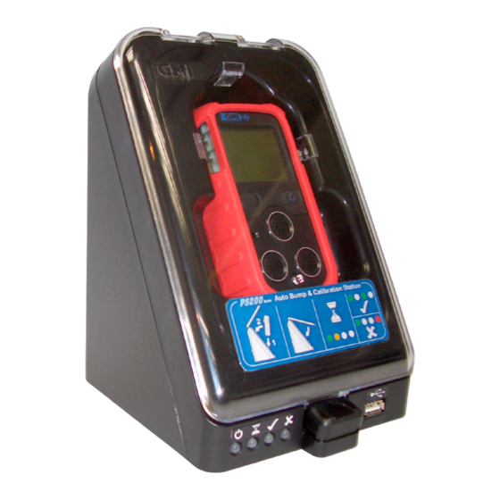
- Page 11 INTRODUCTION Fig. 1-1 PS200 Series Auto Bump / Calibration Station 1.1 GENERAL DESCRIPTION The GMI Personal Surveyor 200 (PS200) Series Auto Bump / Calibration Station provides the user with a quick, easy and reliable method of ensuring that PS200 series instruments are correctly calibrated where company policy dictates.
- Page 12 AUTO BUMP / CAL STATION - HANDBOOK The Auto Bump / Calibration Station can be used for: • A ‘Quick’ Bump Test, approximately 15 seconds gas duration, to verify that the instrument alarms will activate when the alarm setpoints are reached. •...
- Page 13 INTRODUCTION Note: The ‘PASS’ or ‘FAIL’ LED’s indicate the overall result. If any doubt exists about the obtained result, please contact GMI. GMI ‘PS200 Settings’ Software is a Windows™ based ‘stand alone’ application that allows the user to edit test parameters and view and / or print test results.
-
Page 14: Auto Bump / Calibration Hardware
Unit (PSU), and USB Memory Stick with GMI ‘PS200 Settings’ software pre-installed. • A Test Gas Kit (GMI Part No. 64060) is available as an accessory and is supplied complete with Combi Test Gas Cylinder (containing a mixture of 2.5% CH... -
Page 15: (1/4 In. Fittings)
Power Supply Unit (PSU), and USB Memory Stick with GMI ‘PS200 Settings’ software pre-installed. • A Test Gas Kit (GMI Part No. 64060) is available as an accessory and is supplied complete with Combi Test Gas Cylinder (containing a mixture of 2.5% CH... - Page 16 AUTO BUMP / CAL STATION - HANDBOOK...
-
Page 17: Connect Calibration Gas & Power Supply
CONNECT CALIBRATION GAS & POWER SUPPLY 2.1 CONNECT CALIBRATION GAS Gas is supplied to the Auto Bump / Calibration Station from the Combi Test Gas Cylinder (GMI Part No. 99146) via an On ® Demand Flow Regulator (GMI Part No. 99118) and Tygon tubing complete with adaptor (GMI Part No. -
Page 18: Compare Gas Cylinder Label With Software Configuration
AUTO BUMP / CAL STATION - HANDBOOK 2.1.1 Compare Gas Cylinder Label with Software Configuration First of all, make sure that the cylinder is not older than the ‘use by’ date on the label illustrated in Fig. 2-2. Make sure that the cylinder contains enough gas to complete the bump test / calibration. - Page 19 CONNECT CALIBRATION GAS AND POWER SUPPLY The concentrations, illustrated in Fig. 2-2, should be consistent with Auto Bump / Cal Station installed software configuration window, as illustrated in Fig. 2-3. Software Configuration Gas Concentrations Fig. 2-3 Software Configuration After comparing gas values between Cylinder Gas Label and Software Configuration, when consistent, proceed to next paragraph.
-
Page 20: Connect Gas Cylinder To Auto Bump / Cal Station
AUTO BUMP / CAL STATION - HANDBOOK 2.1.2 Connect Gas Cylinder to Auto Bump / Cal Station Connect the On Demand Regulator Valve to the gas cylinder by screwing the valve firmly into the top of the cylinder, as illustrated in Fig. 2-4. Fitting is simplified by pressing the valve on to the cylinder with one hand and turning the cylinder with the other. - Page 21 CONNECT CALIBRATION GAS AND POWER SUPPLY . o/d tubing (not supplied), an adaptor kit (6mm to .) is available as an accessory and supplied as a pack of 3 (Part No. 64085). The adaptor is fitted, as illustrated in Fig. 2-6, before connecting tubing.
-
Page 22: Connect Air / Exhaust Tubing To Auto Bump / Cal Station (If Required)
‘AIR’ inlet and ‘EXHAUST’ outlet adaptors on the rear face of the station using barbed adaptors supplied with the station. GMI recommend the use of an ‘AIR’ in-line filter, also supplied with the station. The (in-line filter) barbed adaptor is a push fit in the ‘AIR’... - Page 23 CONNECT CALIBRATION GAS AND POWER SUPPLY Fig. 2-7 Connect Air Tubing Adaptor to Station The ‘EXHAUST’ line, not illustrated, consists of a length of tubing and a barbed adaptor, supplied with the station. The barbed adaptor is a push fit in the ‘EXHAUST’ outlet adaptor on the rear face of the station.
-
Page 24: Connect Power Supply
AUTO BUMP / CAL STATION - HANDBOOK 2.2 CONNECT POWER SUPPLY Power is supplied to the Auto Bump / Cal Station via a Universal AC Power Adaptor (12Vdc output) supplied with the station. The plug adaptor is located in the 12Vdc socket on the rear face of the station, as illustrated in Fig. -
Page 25: View / Re-Configure Software
VIEW / RE-CONFIGURE SOFTWARE 3.1 VIEW / EDIT SOFTWARE CONFIGURATION The USB Memory Stick, supplied with the Auto Bump / Calibration Station, contains the ‘PS200 Settings’ software in factory default configuration. To view the default configuration settings, insert the Memory Stick into an available USB port on your PC / Laptop. - Page 26 AUTO BUMP / CAL STATION - HANDBOOK Fig. 3-2 Windows Vista™ Fig. 3-3 Windows 7™...
- Page 27 VIEW / RE-CONFIGURE SOFTWARE Select ‘Open folder’ to display the contents, as illustrated in Fig. 3-4. Fig 3-4 USB Contents Folder Note that a shortcut to both Handbook, and the Quick Operation Guide (as included in Auto Bump / Cal Station package), can be accessed from this window.
- Page 28 AUTO BUMP / CAL STATION - HANDBOOK Fig. 3-5 Configuration Window (Default Settings) There are three available ‘Bump Test / Calibrate’ options: • Quick Bump Test • Full Bump Test (with option to calibrate failed ranges) • Calibration...
-
Page 29: Quick Bump Test
The default quick bump test time for applying gas is set at 15 seconds when using the GMI Test Gas Cylinder (Part No. 99146). To select this option, position the cursor on the adjacent radio button then left click mouse button to confirm, as illustrated in Fig. -
Page 30: Full Bump Test (Factory Default)
Fig. 3-8 Default Selection When gas is applied, using the GMI Test Gas Cylinder (Part No. 99146), for a pre-set 60 seconds and when the instrument tolerance band listed below, is reached for each gas range, the Bump / Cal Station will record a ‘Pass’. - Page 31 VIEW / RE-CONFIGURE SOFTWARE If, for any reason, the calibration gas type is changed or the instrument alarm levels are edited, there may be a requirement to use a different gas cylinder type and edit test gases. Calibration Gas Type To change calibration gas type, a selection of flammable calibration gases are available, as illustrated in Fig.
- Page 32 AUTO BUMP / CAL STATION - HANDBOOK Refer to PS200 series Configuration handbook CD-ROM (GMI Part No. 64193). Calibration Gas Values It is important that ‘Testing Gases’ values displayed in window, illustrated in Fig. 3-10, are consistent with values displayed on gas cylinder label.
- Page 33 VIEW / RE-CONFIGURE SOFTWARE Gas Measurement Units Gas measurement units for Carbon Monoxide (CO) and Hydrogen Sulphide (H S) can be displayed as either ‘ppm’ (default) or mg/m . The unit type selected is reflected in Auto Bump / Cal Station stored data and printed Test / Calibration Certificate.
-
Page 34: Calibration
This feature provides the user with the option of performing a full calibration of the instrument. Gas is applied, using the GMI Test Gas Cylinder (Part No. 99146) for a full 60 seconds and the Auto Bump / Cal Station will record a ‘Pass’... - Page 35 VIEW / RE-CONFIGURE SOFTWARE If, for any reason, the calibration gas type is changed or the instrument alarm levels are edited, there may be a requirement to use a different gas cylinder type and edit test gases. Calibration Gas Type To change calibration gas type, a selection of flammable calibration gases are available, as illustrated in Fig.
- Page 36 AUTO BUMP / CAL STATION - HANDBOOK Refer to PS200 series Configuration Handbook CD-ROM (GMI Part No. 64193). Calibration Gas Values It is important that ‘Testing Gases’ values displayed in window, illustrated in Fig. 3-14, are consistent with values displayed on gas cylinder label.
- Page 37 VIEW / RE-CONFIGURE SOFTWARE Gas Measurement Units Gas measurement units for Carbon Monoxide (CO) and Hydrogen Sulphide (H S) can be displayed as either ‘ppm’ (default) or mg/m . The unit type selected is reflected in Auto Bump / Cal Station stored data and printed Test / Calibration Certificate.
-
Page 38: Generate Settings File
AUTO BUMP / CAL STATION - HANDBOOK 3.1.4 Generate Settings File The ‘Generate Settings File’ button, illustrated in Fig. 3-16, allows any configuration changes to be saved to USB Memory Stick, as updated settings file, then transferred to Auto Bump / Cal Station. -
Page 39: Transfer Updated 'Ps200 Settings' Software To Auto Bump / Cal Station
VIEW / RE-CONFIGURE SOFTWARE Firstly, make sure that USB Memory Stick supplied with Auto Bump / Cal Station is inserted in an available USB port on your PC / Laptop. To save changes, position cursor over ‘Generate Settings File’ button then left click mouse to save data to USB Memory Stick. 3.2 TRANSFER UPDATED ‘PS200 SETTINGS’... - Page 40 AUTO BUMP / CAL STATION - HANDBOOK When USB is inserted in station, the updated settings file is automatically transferred to the Auto Bump / Cal Station, indicated by three flashing green LED’s, as illustrated in Fig. 3-18. Fig. 3-18 Transferring Data to Auto Bump / Cal Station On completion of downloading updated settings file, the three LED’s stop flashing.
-
Page 41: Install Instrument In Station & Perform Bump / Calibration
INSTALL INSTRUMENT IN STATION & PERFORM BUMP / CALIBRATION 4.1 INSTALL INSTRUMENT in AUTO BUMP / CAL STATION Before commencing with installation of instrument, make sure that gas is connected to the station and that the 12V power supply is connected to mains wall socket. Switch ON at mains. - Page 42 ‘ON’ indication illuminated, as illustrated in Fig. 4-1. Next, three LED’s coloured orange, orange and red illuminate briefly in sequence, indicating that GMI ‘TEST’ software has started. Finally, the ‘ON’ indication is illuminated as illustrated in Fig.
- Page 43 INSTALL INSTRUMENT IN STATION & PERFORM BUMP / CALIBRATION Locate the instrument inlet connector over the gas supply nozzle in the station, as illustrated in Fig. 4-4. Note 1: The instrument can be either switched ON or OFF when inserted into the Auto Bump / Cal Station. Note 2: The Auto Bump / Cal Station is designed so that the instrument can be installed with or without rubber boot (accessory) fitted.
- Page 44 AUTO BUMP / CAL STATION - HANDBOOK Push the instrument rearwards until correctly seated in the station recess, as illustrated in Fig. 4-5. Fig. 4-5 Instrument Correctly Seated...
- Page 45 INSTALL INSTRUMENT IN STATION & PERFORM BUMP / CALIBRATION Close the front cover of the Auto Bump / Cal Station, as illustrated in Fig. 4-6, then, using both thumbs, press the lower edge corners of the cover firmly until the latch ‘clicks’ shut. Fig.
-
Page 46: Perform Bump / Calibration
AUTO BUMP / CAL STATION - HANDBOOK 4.2 PERFORM BUMP / CALIBRATION The instrument Bump / Calibration operation starts up automatically following the locking of the station cover latch. Fig. 4-7 Perform Bump / Calibration Immediately after the cover latch clicks shut, the orange ‘Test in Progress’... - Page 47 INSTALL INSTRUMENT IN STATION & PERFORM BUMP / CALIBRATION Concurrently, the instrument automatically starts up and begins it’s warm-up routine, if installed in the ‘OFF’ condition. The instrument pump runs briefly before the Station pump ‘overrides’ this and automatically switches OFF the instrument pump.
- Page 48 AUTO BUMP / CAL STATION - HANDBOOK The gas delivery duration is dependent on test type, as follows: Quick Bump Test: 15 seconds default (can be edited in configuration setup from 15 seconds to 60 seconds) Full Bump Test: 60 seconds (fixed) Calibration: 60 seconds (fixed) When the alarm setpoints are reached, the instrument...
- Page 49 INSTALL INSTRUMENT IN STATION & PERFORM BUMP / CALIBRATION The gas values, illustrated in Fig. 4-10, alternate with HIHI / HI or LOLO / LO indication, as illustrated in Fig. 4-11. Fig. 4-11 Instrument in Alarm Condition The instrument’s audible alarms are activated for a short period of time when each range reaches the instrument’s configured alarm setpoint.
- Page 50 AUTO BUMP / CAL STATION - HANDBOOK On completion, the gas values (except oxygen) return to zero, then the instrument initiates a countdown sequence and switches OFF. A ‘PASS’ is indicated by a green LED, as illustrated in Fig. 4-12. Fig.
-
Page 51: Remove Instrument From Auto Bump / Cal Station
INSTALL INSTRUMENT IN STATION & PERFORM BUMP / CALIBRATION 4.3 REMOVE INSTRUMENT from AUTO BUMP / CAL STATION To release the front cover of the Auto Bump / Cal Station, press the cover latch downwards, as illustrated in Fig. 4-14, then open the cover fully. Note that the front cover is designed to remain in the open position as long as necessary. - Page 52 AUTO BUMP / CAL STATION - HANDBOOK CAUTION : Do not overextend angle of extraction as damage to the nozzle could result. Grasp the instrument as shown, lean top of instrument away from station then carefully lift away from gas supply nozzle in the station, as illustrated in Fig.
-
Page 53: Auto Bump / Cal Station Fault Indication
INSTALL INSTRUMENT IN STATION & PERFORM BUMP / CALIBRATION 4.4 AUTO BUMP / CAL STATION FAULT INDICATION Fault detection indication is via the LED’s on the front face of the Auto Bump / Cal Station, as follows: Test Error A ‘Test Error’ is indicated by a orange flashing LED, as illustrated in Fig. - Page 54 AUTO BUMP / CAL STATION - HANDBOOK 4-14...
-
Page 55: View / Print Test Results
These results must be downloaded to a PC / Laptop for viewing or printing. The Memory Stick (Part No. 64184), containing ‘GMI Settings’ software and supplied with the Auto Bump / Cal Station, must be used to download this data. -
Page 56: Download Test Results
AUTO BUMP / CAL STATION - HANDBOOK 5.2 DOWNLOAD TEST RESULTS Make sure that the Auto Bump / Cal Station is connected to Mains power supply, switched ON and start-up is completed. This is indicated by an illuminated green ‘ON’ LED, on the front face of the station, as illustrated in Fig. - Page 57 Next, LED’s coloured orange, orange and red illuminate, as illustrated in Fig. 5-6. This indicates that the test data has been downloaded and GMI ‘TEST’ software has re-started. Fig. 5-6 Test Software Re-started Next, the three (orange, orange and red) LED’s extinguish, leaving only the ‘ON’...
-
Page 58: View / Print Test Results
Using Windows Explorer, locate ‘GMI PS200 SETTINGS’ program as illustrated in Fig. 5-8. Fig. 5-8 Locate Settings Program Position cursor on ‘GMI PS200 SETTINGS’ software program then double click mouse button to select. The window, illustrated in Fig. 5-9, is displayed with disk... -
Page 59: Test Results
VIEW / PRINT TEST RESULTS Fig. 5-9 Disk Contents • Quick Operation Guide: Bump / Calibration poster style document (in PDF format and included in package, Part No. 64186). • Handbook: Auto Bump / Calibration Station User Handbook (in PDF format). •... -
Page 60: Generated Certificates
AUTO BUMP / CAL STATION - HANDBOOK • Generated Certificates: Contains copies of all calibration certificates generated by Auto Bump / Calibration Station. To access any of the above folders, position cursor on required folder then double click mouse button to select. Examples as follows: Test Results: The contents of this folder includes all instrument test... - Page 61 To open a test file, position cursor on the file name then double click mouse button to select. The following example, Fig. 5-11, illustrates information available, including: • Instrument Type (e.g. GMI PS200) • Test Type (e.g. Calibration) • Instr. Serial No (e.g.
- Page 62 AUTO BUMP / CAL STATION - HANDBOOK EXAMPLE (Fig. 5-11):...
- Page 63 VIEW / PRINT TEST RESULTS Test results, as illustrated in Fig. 5-11, can be printed if required. Bump / Cal Station Tested Instruments: The tested files (e.g. Tested000101.rec) in the list, illustrated in Fig. 5-10, identifies serial number of each Auto Bump / Cal Station (e.g.
- Page 64 AUTO BUMP / CAL STATION - HANDBOOK Fig. 5-12 Tested Instruments on 000101 The file includes: • A list of instruments tested • Date Tested (day, month, year) • Time Tested • Test Result ‘P’ PASS or ‘F’ fail 5-10...
- Page 65 VIEW / PRINT TEST RESULTS Generated Certificates: The contents of this folder includes a list of all Bump Test / Calibration Certificates generated when selecting the ‘View Test / Calibration Certificate’ button in the configuration window, as illustrated in Fig. 5-13. The configuration window can be accessed by double clicking mouse button on from the list of items...
-
Page 66: Certificate Content
AUTO BUMP / CAL STATION - HANDBOOK Certificate Content: The certificates, as illustrated in Fig. 5-17 and 5-18, include company details, order number, etc. These details are completed in a ‘Certificate Printer’ window, accessed by clicking mouse button on ‘View Test / Calibration Certificate’... -
Page 67: Include Company Logo
‘Generated Certificates’ folder on the Memory Stick (Part No. 64184). The logo will be included in the top right hand corner of the certificate , as illustrated in ‘GMI’ logo example in ‘Bump Results’ certificate, illustrated in Fig. 5-17. Note: The logo (.jpg) file dimensions must not exceed... -
Page 68: Generated Certificate Files
AUTO BUMP / CAL STATION - HANDBOOK Generated Certificate Files: The certificate files (e.g. Certificate - 05 September 2011 1346. html) in the list, illustrated in Fig. 5-16, identifies date and time of each certificate’s generation. Fig. 5-16 Generated Certificate Files Each ‘.html’... - Page 69 VIEW / PRINT TEST RESULTS Fig. 5-17 Bump Results 5-15...
- Page 70 AUTO BUMP / CAL STATION - HANDBOOK Fig. 5-18 Calibration Certificate 5-16...
-
Page 71: Fit Mounting Bracket
Fig. A-1 Auto Bump / Calibration Station (with mounting bracket fitted) 1.1 GENERAL DESCRIPTION The GMI Personal Surveyor 200 (PS200) Series Auto Bump / Calibration Station is supplied with a mounting bracket and necessary screws to secure the station to a workbench or similar. -
Page 72: Fit Mounting Bracket
AUTO BUMP / CAL STATION - HANDBOOK 1.2 FIT MOUNTING BRACKET 1. Make sure that workbench surface is clean and free from dirt and grime. 2. Place clean cloth or similar on workbench to protect Bump / Cal Station front cover surface from scratching and / or scuffing. -
Page 73: Attach Station To Workbench / Daisy Chain Option
APPENDIX-A 5. Loosely attach two double sems pozi pan screws (Part No. 24957) through bracket and into rear panel of Bump / Cal Station, as illustrated in Fig. A-2. 6. Using a No.2 Pozidrive screwdriver, tighten all four screws to secure. 1.3 ATTACH STATION to WORKBENCH / DAISY CHAIN OPTION The bracket can be secured to a workbench or similar type... - Page 74 AUTO BUMP / CAL STATION - HANDBOOK A group of Bump / Cal Stations can be connected in a ‘daisy chain’ fashion by using a double sems pozi pan screw supplied (Part No. 24957) through bracket at rear of station and into captive nut of adjoining bracket.
- Page 75 INDEX Symbols Calibration 3-10 30 DAY LIMITED WARRANTY ii CALIBRATION GAS 2-1 Calibration Gas Type 3-11 ADDITIONAL Calibration Gas Values ACCESSORIES 1-5 3-12 AGREEMENT, LICENCE i CALIBRATION HARDWARE 1-4 ATTACH STATION to WORKBENCH / DAISY CALIBRATION CHAIN OPTION A-3 SOFTWARE LICENCE i AUTO BUMP / Certificate Content 5-12 CALIBRATION...
- Page 76 AUTO BUMP / CAL STATION - HANDBOOK Connect Gas Cylinder to Auto Bump / Cal Station GAS, CALIBRATION 2-1 Gas Cylinder Label 2-2 CONNECT POWER SUPPLY 2-8 Gas Type 3-11 Content, Certificate 5-12 Gas Values 3-12 COPYRIGHT iii GENERAL DESCRIPTION 1-1, A-1 Generated Certificate Files DAISY CHAIN OPTION...
- Page 77 INDEX Instruments, Tested 5-9 INTRODUCTION REMOVE INSTRUMENT 1-1, 5-1, A-1 from AUTO BUMP / CAL STATION 4-11 Results, Test 5-6 LIABILITY iii RESULTS, TEST 5-1 LICENCE AGREEMENT i Licence, Software i Settings File 3-14 LIMITED WARRANTY ii Software Configuration 2-2 Logo, Company 5-13 SOFTWARE, EDIT 3-1 Software Licence i...
- Page 78 AUTO BUMP / CAL STATION - HANDBOOK Values, Gas 3-12 VIEW / EDIT SOFTWARE CONFIGURATION 3-1 VIEW / PRINT TEST RESULTS 5-1, 5-4 WARRANTY, LIMITED ii...
- Page 80 Head Office Inchinnan Business Park Renfrew Scotland PA4 9RG Tel: +44 (0)141 812 3211 Fax: +44 (0)141 812 7820 sales@gmiuk.com www.gmiuk.com Service & Calibration Centre 25 Cochran Close Crownhill Milton Keynes England MK8 0AJ Tel: +44 (0)1908 568 867 Fax: +44 (0)1908 261 056 service@gmiuk.com Service Centre - USA 25003 Pitkin Road D800...
Need help?
Do you have a question about the PS200 Series and is the answer not in the manual?
Questions and answers