GMI PS200 series User Handbook Manual
Gas measurement
Hide thumbs
Also See for PS200 series:
- Handbook (80 pages) ,
- User manual (73 pages) ,
- Quick operation manual (2 pages)
Table of Contents
Advertisement
Quick Links
Advertisement
Table of Contents

Subscribe to Our Youtube Channel
Related Manuals for GMI PS200 series


Summary of Contents for GMI PS200 series
- Page 1 Gas Measurement Instruments Ltd User Handbook Q 09760...
- Page 2 Your comments can be of great value in helping us to improve our customer publications. Please send any comments that you have to our Sales Department at GMI. Contact details are provided inside the back cover of this handbook. Instrument Service / Repair contact details are also provided inside the back cover of this handbook.
-
Page 3: Software
COPYRIGHT This User Handbook is copyright of Gas Measurement Instruments Ltd (GMI) and the information contained within is for use only with the GMI PS200 series instruments. Reproduction, in whole or in part, including utilisation in machines capable of reproduction or retrieval without written permission of Gas Measurement Instruments Ltd. -
Page 4: Safety
ATEX Directive 94/9/EC and UL913 (7th Edition). Any right of claim relating to product liability or consequential damage to any third party against GMI is removed if the above warnings are not observed. AREAS OF USE Exposure to certain chemicals can result in a loss of sensitivity of the flammable sensor. -
Page 5: Warranty
The GMI PS200 instrument has a warranty against faulty goods or workmanship of 2 years. Consumable and Mechanical parts, e.g. pump, sensors, filters, etc., are not included in this. These are covered under GMI standard warranty conditions. For details, please contact GMI Ltd (UK). - Page 6 USER HANDBOOK...
-
Page 7: Revision Record
RECORD OF REVISIONS REVISION RECORD Date Issue Description Of Change 07/06/2011 New User Handbook (draft). - Page 8 USER HANDBOOK...
-
Page 9: Table Of Contents
CONTENTS TABLE OF CONTENTS COPYRIGHT LIABILITY MODIFICATION NOTICES SOFTWARE DISPOSAL ADVICE SAFETY AREAS OF USE SPECIAL CONDITIONS OF USE STORAGE, HANDLING AND TRANSIT WARRANTY REVISION RECORD INTRODUCTION... - Page 10 USER HANDBOOK 1.1 GENERAL DESCRIPTION 1.2 FEATURES 1.3 DATA LOGGING 1.3.1 Archiving Stored Readings 1.4 FILTERS 1.5 CONSTRUCTION 1.6 IDENTIFICATION LABEL 1.7 PHYSICAL PROPERTIES 1.7.1 Environment 1.8 CERTIFICATION 1.8.1 Certification Marks 1.8.2 Performance OPERATION 2.1 OPERATING PROCEDURE 2.2 SWITCH THE INSTRUMENT ON 2.2.1 Instrument Identification 2.2.2 Battery Status 2.2.3 User Name / Number Only (Option)
- Page 11 CONTENTS 2.2.7 Select Calibration Gas 2.2.8 Sensor Confirmation Check 2.2.9 Normal Operating Display 2-10 2.3 SWITCH THE DISPLAY BACKLIGHT ON / OFF 2-11 2.4 VIEW MAXIMUM AND MINIMUM RECORDED VALUES SINCE SWITCH ON 2-11 2.5 ALARMS RESET OR ACKNOWLEDGE 2-13 2.5.1 Confidence Signal 2-14 2.6 REMOTE SAMPLING (with pump option) 2-14...
- Page 12 USER HANDBOOK 3.6 ALARM CONFIRMATION 3.7 BUMP TEST RESULT ALARMS 4.1 GAS ALARMS 4.1.1 Flammable LEL Alarm Limit 4.1.2 Over-Range Flammable Gas Alarm Function 4.1.3 Oxygen (O2) Alarm Limits 4.1.4 Toxic Alarm Limits 4.2 ACKNOWLEDGE GAS ALARMS 4.3 MUTE ALARMS 4.4 HIGH FLAMMABLE GAS OVER-RANGE ALARM 4.5 FAULT ALARMS...
- Page 13 CONTENTS 4.6 MAN DOWN ALARM (MOTION SENSOR) 4-15 OPERATOR MAINTENANCE 5.1 CLEANING 5.2 REPLACE INSTRUMENT FILTERS 5.2.1 Replace Sensor Hydrophobic Filter 5.2.2 Replace Sample Inlet (Dust) Filter 5.2.3 In-line Hydrophobic Filter (Accessory) RECHARGE BATTERY 6.1 RECHARGE INSTRUMENT BATTERY 6.1.1 Recharge Instrument using the Charging / Comms Clip 6.1.2 Recharge Instrument using the Automatic Bump / Calibration Station...
- Page 14 USER HANDBOOK ACCESSORIES ADDITIONAL INFORMATION 9.1 TRAINING 9.2 WORLD WIDE WEB INDEX...
-
Page 15: Introduction
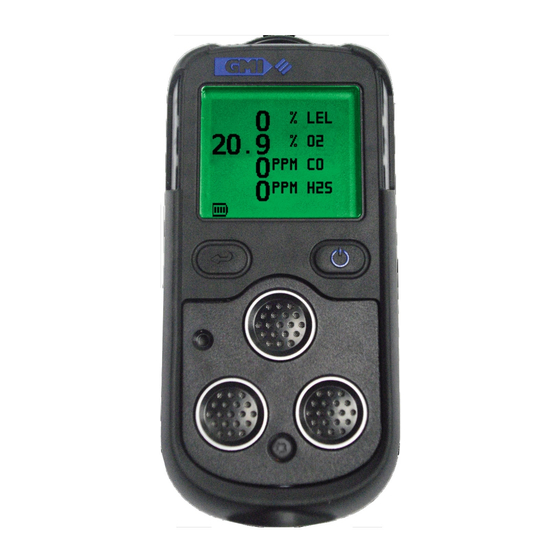
(Fig. 1-1). The PS200 series features high visibility LED’s, a display that changes colour from green to red when an alarm is present, a sounder with a 90dB minimum output and a vibrating alarm. - Page 16 USER HANDBOOK Fig. 1-1 PS200 Series Instrument The PS200 Series has the ability to detect up to 4 of the following gases simultaneously: • 0 to 100% LEL Hydrocarbons • 0 to 25% Oxygen (O • 0 to 1000ppm Carbon Monoxide (CO) •...
- Page 17 INTRODUCTION Fig. 1-2 Display Example (4-Gas) Note: If configured with less sensors, the character size is adjusted accordingly to maximise the display, as illustrated in Fig. 1-3. 1-Gas 2-Gas 3-Gas Fig. 1-3 Display Examples The display, illustrated in Fig’s 1-2 and 1-3, details the current gas readings and operational / status information.
-
Page 18: Features
These options are detailed in italic text, where applicable, and are also detailed in the ‘CONFIGURATION HANDBOOK’.Part No. 64182. 1.2 FEATURES The main features of the PS200 series instrument are: • Compact, lightweight and extremely robust. • Simultaneous detection and display of up to four (4) gases. -
Page 19: Data Logging
• Comprehensive range of accessories available. 1.3 DATA LOGGING Data logging is a standard feature of all PS200 series instruments and allows gas measurements, event logs, bump tests and calibration details to be automatically stored and later downloaded to a Personal Computer (PC) via a USB connection. -
Page 20: Archiving Stored Readings
These filters should be checked regularly and replaced if necessary (refer to ‘FILTER REPLACEMENT’ section in Chapter 5 ‘OPERATOR MAINTENANCE’). 1.5 CONSTRUCTION The PS200 series is housed in a tough, impact resistant moulded case. Sealed to IP67, it can withstand physical impact testing to EN 61779. -
Page 21: Identification Label
INTRODUCTION 1.6 IDENTIFICATION LABEL The label on the rear of the instrument includes serial number and relevant certification details. Fig. 1-5 ID Label 1.7 PHYSICAL PROPERTIES Weight: Without Pump: 215g. (7.6oz.) With Pump: 230g. (8oz.) Dimensions (H x W x D): 121mm. -
Page 22: Certification
USER HANDBOOK 1.8 CERTIFICATION The PS200 series instrument is certified as follows: Note: Check instrument labels for actual certification. ATEX II 2 G EEx ia d IIC T4 Gb (Ta = -20 C to + 50 IECEx EEx ia d IIC T4 Gb (Ta = -20 C to + 50 UL 913 (7th. -
Page 23: Operation
Each time the instrument is used, carry out the following procedure: CAUTION: The GMI PS200 instrument can be supplied with a flammable gas sensor. This sensor is designed for use in concentrations of gas not exceeding the Lower Explosive Limit (LEL). -
Page 24: Switch The Instrument On
USER HANDBOOK • Switch instrument ON in fresh air and check that the battery is fully charged. • Verify there are no faults. • Attach optional accessories, as required. • If oxygen sensor is fitted, check oxygen readings to ensure correct operation. The oxygen sensor responds to the user breathing on the instrument front face (sensor area) by displaying a decreased value, i.e. -
Page 25: Instrument Identification
OPERATION RIGHT HAND (RH) BUTTON Fig. 2-1 PS200 Switch ON 2.2.1 Instrument Identification During warm-up, the instrument display identifies the serial number, software version and battery status information as illustrated in Fig. 2-2: Fig. 2-2 PS200 Series Identification Display... -
Page 26: Battery Status
Fig. 2-3 User Name 2.2.4 Man Down Alarm (Motion Sensor) Option The PS200 series instrument is fitted with a motion sensor. The sensor is disabled by default but can be configured to be either selected at start-up, or always on. The motion sensor will activate an alarm if the instrument is not moved for a pre- set time. -
Page 27: Date And Time
OPERATION If configured to select during the instrument warm-up cycle, the user can enable or disable this feature from operation during the present power cycle, as illustrated in Fig. 2-4. Fig. 2-4 Enable / Disable Motion Sensor The motion alarm is latched and generates both audible and visual alarms. -
Page 28: Calibration Due Date
USER HANDBOOK 2.2.6 Calibration Due Date The calibration due date appears on the display, as illustrated in Fig. 2-6. A configurable option is available not to display this screen. Fig. 2-6 Calibration Due Date If the Calibration Due Date has expired, the following warning is displayed: Fig. -
Page 29: Select Calibration Gas
OPERATION Press the Left Hand (LH) button once to abort the warm-up routine and automatically switch OFF the instrument. Alternatively, a configurable option is available to force the user to switch OFF the instrument. Further details are available from the ‘CONFIGURATION HANDBOOK’... -
Page 30: Sensor Confirmation Check
USER HANDBOOK When the required option is highlighted, press and hold the Right Hand (RH) button to select. Note: Accuracy for the re-selected gas type is + 20%. 2.2.8 Sensor Confirmation Check symbol appears adjacent to each sensor type to confirm that the sensor has been zeroed correctly. - Page 31 OPERATION To acknowledge this fault, press the Right Hand (RH) button once. This will clear the audible / visual alarm and display a flashing spanner symbol alternating with the faulty sensor zero reading. A faulty LEL sensor zero reading is shown in Fig 2-11: Fig.
-
Page 32: Normal Operating Display
USER HANDBOOK Note: If a sensor fault is detected during normal operation of the instrument, the backlight illuminates red, an audible / visual alarm is activated immediately and a spanner symbol is shown adjacent to the faulty sensor type in the display. 2.2.9 Normal Operating Display When warm-up is completed successfully, the backlight switches off and the normal operating screen is displayed,... -
Page 33: Switch The Display Backlight On / Off
OPERATION 2.3 SWITCH THE DISPLAY BACKLIGHT ON / OFF The display screen backlight can be manually switched ON when working in poor lighting conditions. Press the Right Hand (RH) button once to switch the screen backlight ON. It remains ON for 20 seconds and then automatically switches OFF. - Page 34 USER HANDBOOK The example in Fig. 2-15 illustrates the maximum (MAX) gas values stored in a 4-gas instrument. Fig. 2-15 Maximum Gas Values Press the Right Hand (RH) button again to view the minimum gas values stored in the instrument. Note: This screen is only displayed when an Oxygen sensor is fitted in the instrument.
-
Page 35: Alarms Reset Or Acknowledge
OPERATION These readings can be reset by pressing and holding the Right Hand (RH) button for 2 seconds when either MAX / MIN screen is displayed. The instrument will return to the normal operating screen. Fig. 2-17 Normal Operation 2.5 ALARMS RESET OR ACKNOWLEDGE When the instrument detects an alarm set point has been reached, the audible, visual and vibrating alarm will be activated to alert the user. -
Page 36: Confidence Signal
On pumped models, the pump is OFF after start-up. Warning (Hand Aspirator): The PS200 Series is designed to be used with a built-in pump for remote sampling. A hand aspirator can be used for indicative sampling, but it must be noted that when using a hand aspirator, a reading error in the region of + 20% is possible. -
Page 37: Pump Operation
‘PUMP ALWAYS ON’. Fig. 2-18 Pump Symbol Displayed 2.7 SELF TEST The PS200 series instrument has the ability to perform a self test. The test can be performed any time during normal operation of the instrument. In this mode, the instrument tests the buzzer, LED’s, vibration function and displays both the flammable gas type used for calibration and the current username. -
Page 38: Switch The Instrument Off
USER HANDBOOK 2.8 SWITCH THE INSTRUMENT OFF Press and hold both the Left Hand (LH) button the Right Hand (RH) button to switch the instrument OFF. The instrument display starts a countdown from three (3) to OFF. Both buttons must be pressed together until the dis- play goes blank. -
Page 39: Manual Bump Test
A bump test verifies sensor response and alarm operation by exposing the instrument to a known concentration of gas. The PS200 series of instruments can be bump tested either manually or automatically (using the Auto Bump / Calibration Station) . -
Page 40: Manual Bump Options
USER HANDBOOK 3.2 MANUAL BUMP OPTIONS The PS200 series provides two bump test options, QUICK and FULL. The QUICK bump test validates that the alarm threshold has been exceeded for each range. The FULL bump test checks the response of all ranges against set limits. -
Page 41: Applying Test Gas
MANUAL BUMP TEST Fig. 3-2 Apply Gas Screen (4-gas model) 3.4 APPLYING TEST GAS Apply the test gas to the instrument (via the Direct Flow regulator set to 0.5 l/min, as shown in Fig. 3-3. Fig. 3-3 Bump Test Kit 3.5 QUICK / FULL BUMP TEST This stage of the bump test is dependent on whether QUICK or FULL bump is configured. -
Page 42: Quick Bump Test
USER HANDBOOK 3.5.1 Quick Bump Test As the alarm threshold for each range is exceeded, the audible / visual / vibration alarms will activate and a symbol will appear, otherwise a symbol will be displayed. 3.5.2 Full Bump Test After a short period of time, the gas readings are checked against configurable limits. -
Page 43: Bump Test Result
MANUAL BUMP TEST 3.7 BUMP TEST RESULT After selecting ‘YES’ or ‘NO’ the user is informed of the overall bump test result as shown in Fig. 3-5. Fig. 3-5 Bump Test Pass The bump test gas should now be removed. The bump test result including date and time will be auto- matically datalogged. - Page 44 USER HANDBOOK...
-
Page 45: Alarms
ALARMS ALARMS 4.1 GAS ALARMS Gas alarms are enabled when the instrument is switched on and warm-up is complete. All gas ranges have alarm limits that trigger the alarm if the measured gas value exceeds the set level. If a preset alarm level is exceeded, the instrument vibrates, the display backlight illuminates red, the audible alarm sounds, the LED’s flash red and the gas range in alarm flashes on the display. - Page 46 USER HANDBOOK t l u t l u t l u . r t ) y l t l u . r t ) y l i l a i l a N/A = Not Applicable PS200 Series (Default) Alarm Indications...
-
Page 47: Flammable Lel Alarm Limit
ALARMS 4.1.1 Flammable LEL Alarm Limit Two alarm levels, ‘HI’ and ‘HIHI’, are available, each with different pitch and tone. All alarms are user configurable to meet the specific needs of different companies. 4.1.2 Over-Range Flammable Gas Alarm Function The flammable sensor is designed for use in the LEL range only. - Page 48 USER HANDBOOK Note: The toxic gas alarm levels – instantaneous, STEL and LTEL are set at the time of instrument manufacture. It is important that the user ensures that the levels are in accordance with their company’s alarm levels and with health and safety legislation.
-
Page 49: Acknowledge Gas Alarms
ALARMS Fig. 4-2 ‘HIHI’ Alarm Note: See the ‘CONFIGURATION HANDBOOK’ for further information. (Part No. 64182) 4.2 ACKNOWLEDGE GAS ALARMS Once in a safe area, or the gas reading has returned within the preset limits, press and hold the Right Hand (RH) button to mute the alarm sounder and extinguish the gas LED’s. -
Page 50: High Flammable Gas Over-Range Alarm
USER HANDBOOK Latching: If audible alarm has been muted and if gas concentration during that time falls below alarm set point, visual alarm requires to be acknowledged to clear. 4.4 HIGH FLAMMABLE GAS OVER-RANGE ALARM Caution: Exposing the LEL sensor to concentrations of flammable gas above 100% LEL can damage the sensor. -
Page 51: Fault Alarms
ALARMS A timer, counting down from 10 seconds to zero, is displayed together with the message ‘GET OUT’ alternating with ‘HIGH GAS’, as shown in Fig. 4-4: . . . alternating until zero is reached Fig. 4-4 ‘High Gas’ / ‘Get Out’ Timer The instrument must be returned to a gas free area or sample clean air. - Page 52 USER HANDBOOK Fig. 4-5 Low Battery Warning The instrument battery must be re-charged. Note: Gas alarms continue to operate after the ‘LOW BATTERY’ warning appears. ‘BAT FAULT’ warning flashes when approximately 3 minutes operating time remains, as illustrated in Fig. 4-6. The display will be red, the audible alarm sounds continuously and the red LED’s remain on.
-
Page 53: Zero Fault
Switch the instrument OFF and then switch ON again in fresh air. If the fault persists, return the instrument to a GMI approved Service / Repair facility.. The instrument can however still be used to detect and alarm on the other sensor(s) fitted. -
Page 54: Sensor Fault
LEL reading as illustrated in Fig. 4-9, apply test gas for two minutes to allow the display to return to zero then switch instrument OFF and ON again. If fault remains, return instrument to a GMI approved Service / Repair facility. 4-10... - Page 55 LEL gas value as shown in Fig. 4-10, leave instrument on for 30 to 60 minutes then switch instrument OFF and ON again. If fault remains, return instrument to a GMI approved Service / Repair facility. Fig. 4-10 Check Fault 4-11...
-
Page 56: Low Flow - (Pumped Instruments Only)
USER HANDBOOK 4.5.4 Low Flow - (Pumped instruments only) If there is a restricted flow, a “LOW FLOW” warning flashes in the display, the display will be red and both audible alarm and red LED’s will be activated. In this alarm condition, the pump symbol is not displayed. Refer to example Fig. -
Page 57: Calibration Required
ALARMS Fig. 4-12 Flow Fault 4.5.6 Calibration Required If the instrument requires calibration then during warm-up, a ‘CALIBRATION OVERDUE’ warning is displayed. The instrument will operate using its previous calibration settings, however, as the sensors response may have diminished, the instrument should be recalibrated and tested. -
Page 58: Calibration Expired
USER HANDBOOK Press the Left Hand (LH) button once to abort the warm-up routine and automatically switch OFF the instrument. Alternatively, during warm-up, a configurable option is available to force the user to switch OFF the instrument. The following ‘CALIBRATION REQUIRED’ warning is displayed and the instrument is unable to continue without recalibration. - Page 59 ALARMS 4.6 MAN DOWN ALARM (MOTION SENSOR) The motion sensor alarm can be configured ‘NOT USED’ (default), ‘ALWAYS ON’ , or ‘SELECT AT START’ . The sensor will activate an alarm if the instrument is not moved for a pre-set period, configurable from 30 seconds to 5 minutes in 30 second increments.
- Page 60 USER HANDBOOK 4-16...
-
Page 61: Operator Maintenance
The outer, impact resistant, casing of the PS200 Series instrument may be cleaned using a non-abrasive moist cloth. Rub the cloth over the outer casing to remove any dirt and grime. -
Page 62: Replace Sensor Hydrophobic Filter
USER HANDBOOK 5.2.1 Replace Sensor Hydrophobic Filter ® Using a No.1 Pozidrive screwdriver, unscrew the captive screw and remove the filter cover by sliding it away from the display screen to disengage the locating lugs from the corresponding slots in the filter recess. CAPTIVE SCREW LOCATING LUGS FILTER COVER... -
Page 63: Replace Sample Inlet (Dust) Filter
OPERATOR MAINTENANCE Fit a new Hydrophobic Filter (Part No. 64254). Carefully place the hydrophobic filter in position over the instrument sensors, locating filter pin holes over locating pegs in instrument filter recess. Place the filter cover over the filter recess then carefully slide it towards the display screen until the lugs are located in the mating slots in the instrument filter recess. -
Page 64: In-Line Hydrophobic Filter (Accessory)
USER HANDBOOK ® Using a No.1 Pozidrive screwdriver, unscrew then remove the 2 Pozi Pan screws then remove the inlet nozzle complete with inlet filter located in the inner recess of the nozzle. Push the sample inlet filter disc out of inner recess by inserting a matchstick, or similar, into the inlet nozzle outer recess.. - Page 65 OPERATOR MAINTENANCE Fig. 5.3 In-line Hydrophobic Filter To replace the filter, proceed as follows: Unscrew the luer fitting from one side of the the filter in a counter clockwise direction, detach the tubing from the other side then remove the hydrophobic filter.
- Page 66 USER HANDBOOK...
-
Page 67: Recharge Battery
OPERATOR MAINTENANCE RECHARGE BATTERY 6.1 RECHARGE INSTRUMENT BATTERY Use only GMI chargers to recharge PS200 series instruments. CAUTION: Switch the instrument off when charging the internal battery. The battery should be recharged in the following situations: • ‘LOW BATTERY’ flag appears on the display •... -
Page 68: Recharge Instrument Using The Charging / Comms Clip
USER HANDBOOK 3) Using the 12V - USB Vehicle Charging Adaptor (Part No. 64248) In all three options: Once the charger is connected, charging will commence automatically. During charging, the battery symbol and ‘CHARGING’ indication flashes in the display. Maximum recharge duration is 4 hours allowing minimum instrument run times. - Page 69 OPERATOR MAINTENANCE Fit standard type USB connector to power source, as selected from list above. On completion of charging, disconnect standard type USB connector from power source then mini-USB from clip. Grip charging / comms clip and firmly pull away from instrument until tongue on clip disengages with location slot in instrument.
-
Page 70: Recharge Instrument Using The Automatic Bump / Calibration Station
The Automatic Bump / Calibration Station (Part No. 64122 / 64122Q) enables both instrument battery charging and automatic bump testing and calibration of PS200 series instruments to verify that they are suitable for use. The Auto Bump / Calibration Station will accommodate the PS200 series instrument with or without protective rubber boot fitted. - Page 71 OPERATOR MAINTENANCE POWER ON CONNECTOR Fig. 6-2 Charging using Auto Bump / Calibration Station On completion of charging, open the station lid, lift then remove instrument from the unit.
- Page 72 USER HANDBOOK...
-
Page 73: Calibration
CALIBRATION 7.1 GENERAL DESCRIPTION The instrument has been calibrated for particular gases. Where any doubt exists the product should be returned to GMI or an authorised distributor for calibration. WARNING: The instrument must be calibrated and configured by authorised personnel only. -
Page 74: Calibration Validity
Under normal operating conditions a 12 month period can be expected. This is no guarantee, however, as the precise application of the product is unknown to GMI. Individual codes of practice will dictate shorter periods. Regular calibration establishes a pattern of reliability and enables the calibration check period to be modified in line with operational experience. - Page 75 ACCESSORIES ACCESSORIES Accessories supplied with the instrument Part Number Description 64260 Charging / Comms Clip (mini-USB) 64247 Mains Adaptor (c/w USB / mini-USB cable) 64171 User Handbook (CD-ROM) 64172 Quick Operating Instructions 66136 Sample Line Connector - Pumped Instruments Only. ®...
- Page 76 USER HANDBOOK Part Number Description 66478 Hand Aspirator ® (c/w 3.0 metres Tygon Tubing) ® 66118 Tygon Tubing - per metre 66112 Sample Line Extender 66485 In-Line Hydrophobic Filter Assy. 66545 Ball Float Charging Accessories Part Number Description 64248 In-Vehicle Charging Adaptor (12v - USB) Manual Bump / Field Calibration Kit Part Number...
- Page 77 ACCESSORIES Gas Kits for Auto Bump / Calibration Station (Cylinder / Regulator / Tubing) Part Number Description 99146 Combi Test Gas (2.5% CH , 500ppm CO, 50ppm S, 18%O , balance N 64133 Auto Bump / Calibration Kit (Combi Test Gas 99146, Demand Flow regulator c/w 6mm tubing).
- Page 78 USER HANDBOOK...
-
Page 79: Additional Information
ADDITIONAL INFORMATION ADDITIONAL INFORMATION 9.1 TRAINING Training courses are available on all GMI products. Contact GMI Marketing Department for further details: Tel: +44 (0) 141 812 3211 Fax: +44 (0) 141 812 7820 e-mail: sales@gmiuk.com 9.2 WORLD WIDE WEB Visit GMI web site at www.gmiuk.com... - Page 80 USER HANDBOOK...
- Page 81 INDEX INDEX BATTERY, INSTRUMENT ACCESSORIES 8-1 Battery, Low 4-7 ACKNOWLEDGE 2-13 BATTERY, RECHARGE ACKNOWLEDGE GAS ALARMS 4-5 Battery Status 2-4 ADDITIONAL BUMP OPTIONS 3-2 INFORMATION 9-1 BUMP TEST 3-1 ALARM CONFIRMATION BUMP TEST RESULT 3-5 ALARMS 4-1 ALARMS, FAULT 4-7 CALIBRATION 7-1 ALARMS, GAS 4-1, 4-5 Calibration, Automatic 7-1...
- Page 82 USER HANDBOOK CONFIDENCE BEEP FEATURES 1-4 2-14 Field Calibration 7-1 Confidence Signal 2-14 Filter, Hydrophobic 5-2 CONFIRMATION, ALARM FILTERS 1-6 FILTERS, INSTRUMENT CONSTRUCTION 1-6 COPYRIGHT i Flammable LEL Alarm Limit Flow Fault 4-12 DATA LOGGING 1-5 Flow, Low 4-12 Date 2-5 FULL BUMP TEST 3-4 DESCRIPTION, GENERAL 1-1...
- Page 83 INDEX LOGGING, DATA 1-5 Low Battery 4-7 Identification, Instrument Low Flow 4-12 IDENTIFICATION LABEL LTEL 4-3 In-line Hydrophobic Filter MAINTENANCE, (Accessory) 5-4, 6-2, 6-4 OPERATOR 5-1 INFORMATION, ADDI- Man Down Alarm (Motion TIONAL 9-1 Sensor) Option 2-4 INITIATING A MANUAL MANUAL BUMP OP- BUMP TEST 3-2 TIONS 3-2...
- Page 84 USER HANDBOOK OFF, INSTRUMENT 2-16 QUICK / FULL BUMP TEST 3-3 ON, INSTRUMENT 2-2 QUICK BUMP TEST 3-4 Operating Display 2-10 OPERATING PROCEDURE 2-1 RECHARGE BATTERY OPERATION 2-1 RECHARGE OPERATOR INSTRUMENT BATTERY MAINTENANCE 5-1 Option, Pump 2-15 REMOTE SAMPLING OPTIONS, BUMP 3-2 2-14 OVER-RANGE ALARM REPLACE INSTRUMENT...
- Page 85 INDEX Select Calibration Gas 2-7 SELF TEST 2-15 User Name / Number Only Sensor Confirmation (Option) 2-4 Check 2-8 Sensor Fault 4-10 VALIDITY, CALIBRATION Sensor Hydrophobic Filter SENSOR, MOTION 4-15 warm-up 2-3 Sensor, Motion 2-4 WORLD WIDE WEB 9-1 Signal, Confidence 2-14 SOFTWARE i Status, Battery 2-4 Zero Fault 4-9...
- Page 86 USER HANDBOOK...
- Page 88 930 Interstate Ridge Drive, Suite H, Gainesville GA 30501, Telephone (678) 928 4900 Fax (678) 928 4906 e-mail: sales@gmiusa.net GMI Service & Calibration Division: 25 Cochran Close, Crownhill, Milton Keynes, MK8 OAJ, England, U.K. Telephone +44 (0)1908 568867 Fax +44 (0)1908 261056...
Need help?
Do you have a question about the PS200 series and is the answer not in the manual?
Questions and answers
Good day, I recently did my full bump test of 3 GMI Gas detectors. I have found that two of them has sensor fault alarms while calibration and one didn't had any display. The results were failed for all of them. Kindly advise expiry dates for all the sensors, how long these sensors are valid from the MFD date mentioned on the sensors.
The calibration validity for the GMI PS200 series gas detectors is typically 12 months under normal operating conditions. There is no specific expiry date for the sensors mentioned, but calibration must be performed regularly, and individual codes of practice may require shorter calibration periods. The calibration validity remains the responsibility of the user.
This answer is automatically generated