Table of Contents
Advertisement
Advertisement
Table of Contents

Related Manuals for GMI GT Series


Summary of Contents for GMI GT Series
- Page 1 Gas Measurement Instruments Ltd User Handbook...
- Page 2 USER HANDBOOK Issue 9 08/01/2016 Part Number: 67112...
-
Page 3: Copyright
GMI. Reproduction or disassembly of such embodied programmes or algorithms is prohibited. Ownership of such software is not transferable and GMI does not warrant that the operation of the software will be error free or that the software will meet the customer’s requirements. -
Page 4: Safety
1.2.7 of Annex II of the ATEX Directive 94/9/EC. Any right of claim relating to product liability or consequential damage to any third party against GMI is removed if the warnings are not observed. WARNING: To prevent ignition of flammable or combustible atmospheres, remove batteries before servicing. -
Page 5: Special Conditions For Safe Use
WARRANTY GT series instrument has a warranty against faulty goods or workmanship of 5 years. Consumable and mechanical parts are not included in this. These are covered under GMI standard warranty conditions. For details, please contact GMI Ltd (UK). - Page 6 USER HANDBOOK...
-
Page 7: Table Of Contents
CONTENTS COPYRIGHT ................i LIABILITY ................. i MODIFICATION NOTICES ............i SOFTWARE ................i DISPOSAL ADVICE ..............i SAFETY .................. ii SPECIAL CONDITIONS FOR SAFE USE ......iii AREAS OF USE ..............iii STORAGE, HANDLING AND TRANSIT .........iii WARRANTY ................iii INTRODUCTION ..........1-1 1.1 INSTRUMENT RANGES ......... - Page 8 USER HANDBOOK 3.4 FILTER CHECK / FLOW FAULT TEST .... 3-3 3.5 TIME AND DATE ..........3-4 3.6 CALIBRATION DUE DATE....... 3-4 3.7 SERVICE DUE DATE ........3-8 3.8 SENSORS ZEROING ........3-11 3.9 SWITCH THE INSTRUMENT OFF OR RE-ENTER THE MODE MENU ......3-12 LEAK TEST MODE ..........
- Page 9 CONTENTS 5.7 CSM ALARMS ..........5-6 5.8 CSM LOGGING ..........5-6 5.9 CSM CONFIDENCE SIGNAL ......5-7 BARHOLE TESTING MODE ....... 6-1 6.1 BARHOLE RANGES ........6-1 6.2 BARHOLE FEATURES ........6-1 6.3 BARHOLE DISPLAYS ........6-2 6.4 VIEW BARHOLE RESULTS ......6-7 6.5 BARHOLE OPERATION ........
- Page 10 USER HANDBOOK PURGE MODE ............ 8-1 8.1 PURGE RANGES ..........8-1 8.2 PURGE FEATURES ........8-1 8.3 PURGE DISPLAYS .......... 8-1 8.4 PURGE BUTTON OPERATION ....... 8-2 8.5 DESCRIPTION OF PURGE BUTTON OPERATION ............8-3 8.6 PURGE ALARMS ..........8-4 SNIFFER MODE ..........
- Page 11 CONTENTS 10.6 DESCRIPTION OF PRESSURE BUTTON OPERATION ............10-3 10.7 PRESSURE ALARMS ........10-4 BUMP TEST MODE .......... 11-1 11.1 BUMP TEST RANGES ........11-1 11.2 BUMP TEST FEATURES ......11-1 11.3 BUMP TEST DISPLAYS .......11-2 11.4 BUMP TEST BUTTON OPERATION ....11-5 11.5 BUMP TEST LOGGING ........11-6 ALARMS ............
- Page 12 USER HANDBOOK 13.3 BATTERY REPLACEMENT ...... 13-12 13.3.1 Remove and Replace Batteries ..... 13-13 13.3.2 Charging (Rechargeable) Batteries..13-17 CALIBRATION ........... 14-1 14.1 CALIBRATION VALIDITY ......14-2 ACCESSORIES..........15-1 ADDITIONAL INFORMATION ......16-1 Training ..............16-1 World Wide Web ........... 16-1 TYPICAL OPERATING PARAMETERS ....A-1 Dimensions (excluding probe) .........
-
Page 13: Introduction
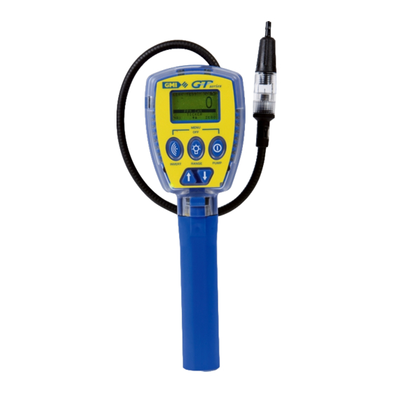
INTRODUCTION GT series The GMI instruments are designed to be multifunction, multi-application gas detectors to suit all the needs of a Gas Industry Service Technician. GT series Fig. 1.1 Instrument Centre In the following procedure, the five instrument buttons shown in Fig 1.2 are referred... -
Page 14: Instrument Ranges
USER HANDBOOK Button Text Reference LH (INVERT): LH button Centre button Centre (RANGE): RH button RH (PUMP): UP button Down: DOWN button T h e b o t t o m l i n e o f t h e i n s t r u m e n t d i s p l a y m a y indicate button press options. - Page 15 Note 2: Some sensors respond to gases other than the target gas. Typically, this cross response is not enough to result in operational problems, however, should you have any concerns, please contact GMI.
- Page 16 USER HANDBOOK...
-
Page 17: General Features
GENERAL FEATURES • An integral pump draws the required sample over all of the sensors • The pump flow is monitored by means of a pressure transducer • Datalogging is available for some applications • A ‘Bleep’ sounds for each button press •... -
Page 18: Modes Of Operation
USER HANDBOOK 2.1 MODES OF OPERATION Leak Test: This mode is for the technician to investigate odour or leak complaints and to pinpoint the leak. See Chapter 4 for ‘Leak Test’ mode operation. Confined Space: Used for confined space pre-entry testing and for personal monitoring in areas such as basements etc. -
Page 19: Operating Procedure
OPERATING PROCEDURE Check the following: • The instrument is clean and in good condition. • The batteries are in good condition, fully charged and fitted correctly. • The hydrophobic filter is clean and in good condition. • The sample line and any other accessories used are in good condition. -
Page 20: Switch The Instrument On
USER HANDBOOK Each time you use the instrument, carry out the following procedure: 3.1 SWITCH THE INSTRUMENT ON To switch the instrument ON in fresh air: • Press and hold the RH button , for one second. Fig. 3.1 Switch ON The instrument begins its warm-up routine, which lasts approximately 30 seconds. -
Page 21: Battery Status
OPERATING PROCEDURE 3.3 BATTERY STATUS This feature provides the user 100% with a battery capacity level indicator that displays instrument battery power remaining, as shown in Fig. 3.3. This battery symbol will be indicated for approximately five (5) seconds during the warm- up cycle, then on the top of the Fig. -
Page 22: Time And Date
USER HANDBOOK A successful flow fault test is confirmed, as shown in Fig. 3.6, by ‘successful’ flashing in the display. If the instrument fails the flow fault test, the screen shown in Fig. 3.5 is displayed. alternating with The instrument stores a log of a successful test. - Page 23 OPERATING PROCEDURE Calibration due date is displayed, as shown in Fig. 3.8. Fig. 3.8 Calibration Due Date The screen, shown in Fig. 3.9, is displayed when the Calibration date has expired. i.e. overdue. After approximately five seconds, the instrument warm-up continues. Fig.
- Page 24 USER HANDBOOK The user must acknowledge that Calibration has expired. To continue: • Press and hold YES for instrument warm-up to continue. To switch OFF: • Press and hold NO The screen, shown in Fig. 3.12, is displayed. Fig. 3.12 Switch OFF •...
- Page 25 OPERATING PROCEDURE The user must acknowledge that Calibration has expired. Note: The extended period can be set from 1 to 31 days To accept ‘extended period’ option: • Press and hold YES and the instrument warm-up continues. Note: When the extended period option expires, the user will be forced to switch the instrument OFF.
-
Page 26: Service Due Date
USER HANDBOOK To proceed with the switch-off sequence. • Press and hold both the LH button and the RH button simultaneously. 3.7 SERVICE DUE DATE The Service due date can be set by the workshop and is set to two (2) years by default from last service date. - Page 27 OPERATING PROCEDURE 3. Service Due Date message is displayed with user acknowledge if overdue. S e r v i c e d u e d a t e i s displayed, as shown in Fig. 3.20. Fig. 3.20 Service Due Date The screen, shown in Fig.3.21, is displayed when the Service date has...
- Page 28 USER HANDBOOK 4. Service Due Date message is displayed with user acknowledge for extended period option, if overdue. Service Due Date message is displayed, as shown in Fig. 3.23. Fig. 3.23 Service Due Date If overdue but within the ‘extended period’, the screen, shown in Fig.
-
Page 29: Sensors Zeroing
OPERATING PROCEDURE • Press and hold both the LH button and the RH button simultaneously to proceed with the switch-off sequence. 5. Service Due Date message is displayed with user shut- down if overdue. S e r v i c e d u e d a t e i s displayed, as shown in Fig. -
Page 30: Switch The Instrument Off Or Re-Enter The Mode Menu
USER HANDBOOK Warm-up Complete The instrument will now automatically select the Leak Test Mode, as default. The following configurable options are available: To start up in specific operational mode. To start up in the mode last used. 3.9 SWITCH THE INSTRUMENT OFF OR RE-ENTER THE MODE MENU To initiate the shut down sequence: •... - Page 31 OPERATING PROCEDURE After this time, the OFF sequence countdown begins and the user will have to keep the buttons pressed for a further three (3) seconds to switch the instrument OFF. The countdown sequence is shown in Fig. 3.30. Note: In Confined Space Mode, to prevent inadvertently switching instrument OFF or changing mode while alarms are active, the user must press and hold both the LH...
- Page 32 USER HANDBOOK To highlight the required option: • Press the UP or DOWN buttons, then . . To select the highlighted option: • Press and hold OK 3-14...
-
Page 33: Leak Test Mode
LEAK TEST MODE This mode is for the technician to investigate odour or leak complaints and to pinpoint the leak. Note: The instrument pump must be switched ON to measure in Leak Test mode. 4.1 LEAK TEST RANGES Leak Test mode will have the following ranges available for normal operation: •... -
Page 34: Leak Test Displays
USER HANDBOOK 4.3 LEAK TEST DISPLAYS During the warm-up period, all applicable sensors will be checked and the display will indicate any sensor faults. A positive zero fault is indicated by a flashing gas reading, as illustrated in Fig. 4.1. A negative zero fault is indicated alternating with by a spanner alternating with... - Page 35 LEAK TEST MODE 4.3.1 Ticker (Geiger) To enable / disable the audible Ticker (Geiger): (in the PPM range) • Press and hold the UP and DOWN buttons simultaneously, as follows: First press and hold - to enable visual only. Second press and hold - to disable both audible and visual. Third press and hold - to enable both audible and visual.
- Page 36 USER HANDBOOK If a CO sensor is included in your instrument and the CO concentration rises above a pre- set level, the display will change together with an audible alarm to attract your attention. If alarm is enabled, CO alternates with HIHI until cleared.
-
Page 37: Leak Test Button Operation
LEAK TEST MODE 4.4 LEAK TEST BUTTON OPERATION A summary of the button operation is detailed in Table 4.1: CENTRE (INVERT) (RANGE) (PUMP) ACTION PUMP RANGE ON / OFF INVERT FLAM PRESS DISPLAY CLEAR FLOW FLAM + CO FAULT PRESS MAX / LIVE FLAM PPM BACKLIGHT /... - Page 38 USER HANDBOOK 4.5.2 Ticker (Geiger) Adjust To adjust the Ticker (Geiger) threshold: To increase • Press and hold the UP button. To decrease • Press and hold the DOWN button. T h e t h r e s h o l d s e t t i n g i s displayed briefly beneath the PPM CH .
- Page 39 LEAK TEST MODE To switch ON the flashlight: • Press and hold the Centre button again. The backlight and flashlight are both timed to switch OFF after two minutes. Both can be switched OFF by a third press and hold of the Centre button 4.5.5 Max / Live To show the Maximum readings:...
- Page 40 USER HANDBOOK 4.5.7 Pump To switch the pump ON and OFF: • Press the RH button 4.5.8 Zero To zero the Flammable PPM range when displayed: • Press and hold the RH button Note: The pump must be switched ON to zero the flammable ppm range.
-
Page 41: Leak Test Ticker (Geiger) Function
LEAK TEST MODE 4.6 LEAK TEST TICKER (GEIGER) FUNCTION The Ticker (Geiger) function is available on flammable ppm range. The Ticker (Geiger) range at start-up is 0-1000 PPM. For any subsequent PPM concentration, the Ticker (Geiger) audible / visual can be ‘backed off’ using the UP or DOWN buttons. -
Page 42: Leak Test Alarms
USER HANDBOOK 4.7 LEAK TEST ALARMS Refer to Chapter 11. 4.8 LEAK TEST LOGGING Automatic datalogging is active for CO and CH ranges (except ppm ). Timed logs will be recorded every minute (default) or as per configuration. 4-10... -
Page 43: Confined Space Mode
CONFINED SPACE MODE This mode is used for confined space pre-entry testing and for personal monitoring in areas such as basements etc. 5.1 CSM RANGES Confined Space Mode (CSM) will have the following ranges available: • 0 – 100% LEL Methane (CH ) Flammable (EEE Over-range) and option to display up to 9.9% LEL with 0.1% resolution... -
Page 44: Csm Displays
USER HANDBOOK 5.3 CSM DISPLAYS During the warm-up period, all applicable sensors will be checked and the display will indicate any sensor faults. A positive zero fault is indicated by a flashing gas reading, as illustrated in Fig. 5.1. alternating with A negative zero fault is indicated by a spanner alternating with a zero reading (not illustrated). -
Page 45: Csm Button Operation
CONFINED SPACE MODE When viewing Max in confined space mode, Confined Max identifier is in the top of the display, with the option of selecting Min on the bottom line, as shown in Fig. 5.3: Fig. 5.3 Confined Max Identifier When viewing Min in confined space mode, Confined Min identifier is in the top of the... -
Page 46: Description Of Csm Button Operation
USER HANDBOOK 5.5 DESCRIPTION OF CSM BUTTON OPERATION 5.5.1 Lights To switch ON the backlight: • Press and hold the Centre button To switch ON the flashlight: • Press and hold the Centre button again. The backlight and flashlight are both timed to switch OFF after two minutes or can be switched OFF by a third press and hold the Centre button 5.5.2 Min / Max... - Page 47 CONFINED SPACE MODE 5.5.3 Alarm Acknowledge HIHI, LOLO for O (if fitted), and Time Weighted Average (TWA) alarms are latching by default. The AL / ACK will only cancel the alarms if all gases have returned to “safe” levels. An option of HI, or LO for O (if fitted), non latching alarms are available, as follows: When the reading drops below the alarm level, the alarm will...
-
Page 48: Csm Pump
USER HANDBOOK Note: When a manual log is taken, the term ‘LOG’ is inversed on the display for one (1) second to provide a visual confirmation that the log has been captured. 5.5.6 Menu / Off To re-select the Mode Menu: •... -
Page 49: Csm Confidence Signal
CONFINED SPACE MODE 5.9 CSM CONFIDENCE SIGNAL During normal operation, the instrument sounds a confidence beep and illuminates the bottom pair of red LED’s briefly every 15 seconds. This function is programmable in the instrument setup software. The confidence signal function makes the user aware that the instrument is operating correctly: Note: The confidence beep and / or LED indication can be disabled. - Page 50 USER HANDBOOK...
-
Page 51: Barhole Testing Mode
BARHOLE TESTING MODE This mode is used to locate underground leaks and on start-up will be ranged to 0-100% LEL Methane (CH ) Flammable which will autorange to VOL Methane (CH ) Flammable at 100% LEL. 6.1 BARHOLE RANGES Barhole testing will have the following ranges available: •... -
Page 52: Barhole Displays
USER HANDBOOK 6.3 BARHOLE DISPLAYS During the warm-up period, all applicable sensors will be checked and the display will indicate any sensor faults. A p o s i t i v e z e r o f a u l t i s indicated by a flashing gas reading, as illustrated in Fig. - Page 53 BARHOLE TESTING MODE 6.3.1 Timed Mode If TIMED is selected, and the instrument configuration allows user selectable barhole sample time, the screen shown in Fig. 6.3 is displayed. The sample time previously set is displayed. If the instrument configuration does not allow user selectable barhole sample time, the screen shown in Fig.
- Page 54 USER HANDBOOK Stop purge when the live readings reach zero: To stop purge: • Press and hold OK T h e f i r s t b a r h o l e screen is displayed as shown in Fig. 6.5. Fig.
- Page 55 BARHOLE TESTING MODE • Between Barhole tests there is a mandatory ‘Purge’ mode to ensure that any gas in the instrument is cleared before the next barhole is sampled. • During purge, the peak reading is reset to zero a n d b l a n k e d f r o m display, as shown in Fig.
- Page 56 USER HANDBOOK The first barhole screen is then displayed, as shown in Fig. 6.9 Fig. 6.9 Non Timed Mode of Operation Up to six barhole readings can be stored. These are identified as ‘Barhole 1’ to ‘Barhole 6’. After the first reading is stored (as Barhole 1), the second reading (Barhole 2) will be automatically selected, however, by using the UP or DOWN buttons the user can specify where the next...
-
Page 57: View Barhole Results
BARHOLE TESTING MODE 6.4 VIEW BARHOLE RESULTS To view previous barhole results: (to a maximum of six barhole tests) • Press and hold VIEW Fig. 6.10 View Barhole Results To return the display to normal operation: • Press and hold LIVE If a *Flow Fault or **Bead Fault is detected during a barhole test, the pump will stop and... -
Page 58: Barhole Operation
USER HANDBOOK 6.5 BARHOLE OPERATION A summary of the button operation is detailed in the following table: CENTRE (INVERT) (RANGE) (PUMP) ACTION INVERT CLEAR FLOW PRESS DISPLAY FAULT PRESS BACKLIGHT / START / STOP / VIEW FLASHLIGHT PURGE HOLD Table. 6.1 Button Operation in Barhole Mode 6.6 DESCRIPTION OF BARHOLE BUTTON OPERATION 6.6.1 View... - Page 59 BARHOLE TESTING MODE 6.6.3 Flow Fault If a flow fault is detected, the pump stops automatically. If a sample was in progress then current sample is halted and ‘Purge’ cycle will be the next part of the sequence. If flow fault is indicated, the instrument should be checked for water ingress or blockage.
-
Page 60: Barhole Alarms
USER HANDBOOK 6.7 BARHOLE ALARMS There are no Gas Alarms in this mode. 6-10... -
Page 61: Co (Carbon Monoxide) Mode
CO (CARBON MONOXIDE) MODE The CO mode is used to check the interior of premises and appliances for CO leakage. 7.1 CO RANGES The CO mode can have the following ranges available: • 0 – 2000 ppm Carbon Monoxide (CO) •... -
Page 62: Co Displays
USER HANDBOOK To highlight the required option: • Use the UP and DOWN buttons. To select the highlighted option: • Press and hold OK Note 1: The highlighted option will be that previously used. Note 2: If an O2 sensor is not fitted then the Airfree Option is automatically unavailable. - Page 63 CO (CARBON MONOXIDE MODE) 7.4.1 CO Direct I n t h i s o p t i o n , n o r m a l atmospheric air is checked for CO content. The typical display for this mode is shown in Fig. 7.3: Fig.
- Page 64 USER HANDBOOK T h i s i s t h e C O r e a d i n g m o d i f i e d b y t h e O r e a d i n g (only applicable if O sensor is fitted).
- Page 65 CO (CARBON MONOXIDE MODE) Note 2: A proper ‘DIF’ reading will only be obtained if there is a preceding DIFZ (zeroing). Note 3: Before viewing logs from the differential mode, a manual ‘zero’ must be performed as a reference point. If this has not been done, since the last clear, a ‘zzz’...
-
Page 66: Co Button Operation
USER HANDBOOK 7.5 CO BUTTON OPERATION A summary of the button operation is detailed in table 7.1: CENTRE (INVERT) (RANGE) (PUMP) ACTION PUMP ON / OFF INVERT PRESS DISPLAY CLEAR FLOW FAULT MANUAL PRESS ZERO BACKLIGHT / FLASHLIGHT CLEAR OK (CONTINUE) HOLD VIEWING VIEWING... - Page 67 CO (CARBON MONOXIDE MODE) 7.6.3 Manual Log A manual log can be taken at any time provided that the pump is running. To capture a manual log: • Press and hold LOG Note: When a manual log is taken, the term ‘LOG’ is inversed on the display for one (1) second to provide a visual confirmation that the log has been captured.
-
Page 68: Co Alarms
USER HANDBOOK 7.7 CO ALARMS There are no alarms in this mode. 7.8 CO LOGGING Automatic datalogging is active and manual logs can also be captured. Timed logs will be taken every minute (default) or as per configuration. For direct CO and differential CO, the direct CO reading will be logged. -
Page 69: Purge Mode
PURGE MODE The purge mode is used in gas and air purging applications. 8.1 PURGE RANGES Purge mode will have the following ranges available: • 0 – 100% VOL Methane (CH ) Flammable • 0 – 25% Oxygen (O ) if fitted 8.2 PURGE FEATURES Purge mode has the following features available: •... -
Page 70: Purge Button Operation
USER HANDBOOK After the sensor check the normal display will be shown, as in Fig. 8.2: Fig. 8.2 Normal Display To display both % Gas and % O (as shown in Fig. 8.3) • Press the Centre button Fig. 8.3 Gas and Oxygen Display 8.4 PURGE BUTTON OPERATION A summary of the button operation is detailed in Table 8.1:... -
Page 71: Description Of Purge Button Operation
PURGE MODE 8.5 DESCRIPTION OF PURGE BUTTON OPERATION 8.5.1 Lights To switch ON the backlight: • Press and hold the Centre button To switch ON the flashlight: • Press and hold the Centre button again. The backlight and flashlight are both timed to switch OFF after two minutes. -
Page 72: Purge Alarms
USER HANDBOOK 8.5.5 Range The range button allows the selection of the % Gas only display or the % Gas plus % O display. 8.5.6 Flow Fault If flow fault is detected, the pump stops automatically. The instrument should be checked for water ingress or blockage. To clear the flow fault: (Once the blockage has been cleared) •... -
Page 73: Sniffer Mode
SNIFFER MODE This mode is used to find small fitting leaks. Fast detection rates are achieved using a semiconductor sensor in the probe. 9.1 SNIFFER RANGES Sniffer mode will have the following ranges available: • 0 – 10,000 ppm Methane (CH ) Flammable 9.2 SNIFFER FEATURES Sniffer mode will have the following features:... -
Page 74: Sniffer Displays
USER HANDBOOK 9.3 SNIFFER DISPLAYS During the warm-up period, all applicable sensors will be checked and the display will indicate any sensor faults. A positive zero fault is indicated by a flashing gas reading, as illustrated in Fig. 9.1. alternating with A n e g a t i v e z e r o f a u l t is indicated by a spanner alternating with a zero reading... -
Page 75: Sniffer Button Operation
SNIFFER MODE 9.4 SNIFFER BUTTON OPERATION A summary of the button operation is detailed in Table 9.1: CENTRE (INVERT) (RANGE) (PUMP) ACTION PUMP INVERT ON / OFF PRESS DISPLAY CLEAR FLOW FAULT PRESS BACKLIGHT / ZERO FLASHLIGHT HOLD Table 9.1 Button Operation in Sniffer Mode 9.5 DESCRIPTION OF SNIFFER BUTTON OPERATION 9.5.1 Lights To switch ON the backlight:... - Page 76 USER HANDBOOK 9.5.3 Zero To zero the ppm range • Press and hold the RH button Note: The pump must be switched ON to zero the ppm range. 9.5.4 Flow Fault If flow fault is detected, the pump stops automatically. The instrument should be checked for water ingress or blockage.
-
Page 77: Sniffer Ticker (Geiger) Indication
SNIFFER MODE 9.5.7 Menu / Off To re-select the Mode Menu: • Press and hold both the LH button and RH button When the menu appears on the screen, release the buttons, otherwise the instrument will proceed into the switch OFF process and will switch OFF after a further three (3) seconds. - Page 78 USER HANDBOOK 9.6.1 Select Audible / Visual Ticker (Geiger) Combination Option The Ticker (Geiger) function can be set for audible and visual combination options as follows: Both ON; Audible OFF / Visual ON; Both OFF; Both ON; etc. To select required audible / visual combination option: •...
-
Page 79: Pressure Mode
PRESSURE MODE In this mode, the instrument can be used as a manometer to measure appliance and regulator pressure and to check the system for leaks. Note 1: It is important to zero the pressure mode in ambient atmosphere before taking measurements. Note 2: Pump is OFF in pressure mode. -
Page 80: Prepare Instrument (Pressure Mode)
USER HANDBOOK Note: A configurable option is available to measure in mBar as shown in Fig. 10.2. Fig. 10.2 mBar Display 10.4 PREPARE INSTRUMENT (PRESSURE MODE) Zero the instrument before tubing is attached. To zero the instrument: • Press and hold ZERO Connect the required length of tubing from the appliance to the pressure port on the rear of the instrument, as shown in Fig. -
Page 81: Pressure Button Operation
PRESSURE MODE 10.5 PRESSURE BUTTON OPERATION A summary of the button operation is detailed in Table 10.1: CENTRE (INVERT) (RANGE) (PUMP) ACTION INVERT PRESS DISPLAY PRESS ZERO BACKLIGHT HOLD Table. 10.1 Button Operation in Pressure Mode 10.6 DESCRIPTION OF PRESSURE BUTTON OPERATION 10.6.1 Lights To switch ON the backlight:... -
Page 82: Pressure Alarms
USER HANDBOOK 10.6.3 Menu / Off To re-select the Mode Menu: • Press and hold both the LH button and RH button When menu appears on the screen, release the buttons, otherwise the instrument will proceed into the switch OFF process and will switch OFF after a further three (3) seconds. -
Page 83: Bump Test Mode
BUMP TEST MODE This mode is to allow the user to periodically test the instrument against known gas concentrations. This mode is disabled by default. 11.1 BUMP TEST RANGES All the gas ranges that are present in the GT are available in this mode: •... -
Page 84: Bump Test Displays
USER HANDBOOK 11.3 BUMP TEST DISPLAYS On entering bump test mode, the first screen is shown: Each gas type / concentration is stored using a CalGas number, e.g. PPM may be stored as CalGas 1; LEL as CalGas 2; etc. Fig. - Page 85 Note 1: As soon as either the UP or DOWN buttons are touched and when there is no value displayed, a value one unit away from the GMI default value, is automatically displayed. This assists the user to enter the required gas concentration more quickly.
- Page 86 USER HANDBOOK To exit current gas range and return to main menu: • Press and hold EXIT To return to CalGas selection display: • Press and hold OK From CalGas set-up screen, Fig. 11-5, the user can also view the previous 32 bump tests.
-
Page 87: Bump Test Button Operation
BUMP TEST MODE To select highlighted option: • Press and hold NEXT The screen, shown opposite, displays the previously stored bump test data: Fig. 11-7 Stored Bump Test Data To return to CalGas Display: • Press and hold OK 11.4 BUMP TEST BUTTON OPERATION A summary of the button operation is detailed in Table 11.1. -
Page 88: Bump Test Logging
Up to 32 different bump tests are stored in chronological order. If any more are done, the oldest will be over-written. The data can be extracted from the GT using the GT Data Downloading software package (GMI Part no. 67164). 11-6... -
Page 89: Alarms
ALARMS 12.1 GAS ALARMS The following gas alarms are available according to gas type and are programmable according to application and / or customer preference. (See Tables 12.1 and 12.2). 12.2 FLAMMABLE (LEL) ALARMS Up to three (3) instantaneous alarm levels are programmable. All three are rising alarms, i.e. - Page 90 USER HANDBOOK averaging essentially makes the instrument single user applicable. The option is available to restart the averaging after each instrument switch-off, thus allowing for multiple user application. A TWA alarm is intermittent with the actual gas reading, therefore it is possible to get a value of zero (0) and an LTEL or STEL alarm.
- Page 91 ALARMS Example 2: Example 2 (Fig. 12.2) shows the instrument signalling a ‘ ’ HIHI LEL alarm. Again the alarm warbles and all eight (8) LED’s ramp. If more than one gas alarm level is exceeded, the gas value will flash for each type in alarm.
- Page 92 USER HANDBOOK Example 4: Example 4 (Fig. 12.4) shows an instrument in Leak Test ‘ ’ Mode with a LEL alarm. The audible alarm indication is a high pitch tone together with four flashing LED’s. Toggles to Fig. 12.4 HI LEL Alarm Example 5: Example 5 (Fig.
- Page 93 ALARMS Example 6: Examples 6 and 7 (Fig. 12.6 and Fig. 12.7) shows an instrument in Confined Space Mode with Time Weighted Average STEL and LTEL H alarms for toxic sensors. In both cases, the audible alarm Toggles to warbles and eight (8) LED’s ramp.
-
Page 94: Alarm Types
The following Table 12.1 shows the GMI default selections. Latching or non-latching options exist in all allowable alarms. Alarms are allowed in Leak Test Mode and CSM Mode only. - Page 95 ALARMS ALARM TYPE LATCHING MUTE AUDIBLE VISUAL LED DISPLAY Yes / No Yes / No INDICATION INDICATION LEL Warning N / A N / A N / A Flash Range High Pitch Toggle LEL ( (4) Flashing Tone Hi / Conc High Pitch Toggle HIHI...
- Page 96 Lo Lo Table. 12.2 Alarm Options Note: Where there is a square with a number, it means that the GMI default is to have these alarms active at the gas concentration shown by the number. Where there is a square without a number, it means that this alarm option is available should the user wish to have it activated.
-
Page 97: Fault Alarms
ALARMS 12.6 FAULT ALARMS Refer to Alarms Table 12.1 to identify the audible / visual indication for any of the following faults. 12.6.1 Low Battery The battery symbol is displayed on the screen intermittently with . When the instrument’s battery power is low, i.e. approximately 30 minutes operating time remaining, the audible alarm sounds once every two seconds and the Orange LED flashes. - Page 98 USER HANDBOOK The faulty sensor will cause the instrument to display a flashing spanner symbol to warn the user that this sensor is not working correctly, as shown in Fig. 12.8: alternating with Fig. 12.8 Zero Fault 12.6.3 Sensor Fault There are two types of sensor fault as illustrated in the following displays: If a “ZERO FAULT”...
- Page 99 ALARMS If a “ZERO FAULT” flag and a flashing s p a n n e r s y m b o l appear, alternating with a gas value as shown in Fig. 12.10, l e a v e i n s t r u m e n t o n f o r 3 0 t o 6 0 alternating with minutes then switch...
- Page 100 USER HANDBOOK To clear the flow fault: • Press the RH button • Press and hold FLOW ACK (in Confined Space Mode only) Note: In Confined Space mode, the pump will not switch off if a sample fault exists. 12.6.5 Calibration Expired During the warm up of the instrument, a check is done to verify if the calibration date has expired.
- Page 101 ALARMS 12.6.7 Service Expired During the warm up of the instrument, a check is done to verify if the service date has expired. If the instrument is configured to pause if service is due, the user is asked to continue or not. If yes is selected, the user can continue using the instrument as normal.
- Page 102 USER HANDBOOK 12-14...
-
Page 103: Operator Maintenance
Do not use abrasive materials or strong volatile chemical solutions as these could damage the impact resistant casing. GT series The outer, impact resistant casing of the instrument may be cleaned using a non-abrasive moist cloth. -
Page 104: Dust Filter
USER HANDBOOK 13.2.1 Dust Filter Hold the probe adaptor then unscrew the dust filter holder in a counter clockwise direction to remove the filter holder from the adaptor, as illustrated in Fig. 13.1. Note: The dust filter washer is not removed at this stage. DUST FILTER HOLDER DUST FILTER WASHER (Part No. -
Page 105: Hydrophobic Filter
OPERATOR MAINTENANCE Hold the probe adaptor then attach dust filter holder to the adaptor by turning in a clockwise direction until secure. Note: Care must be taken not to overtighten the dust filter holder. Switch the instrument ON then check that a sample / flow fault is displayed when the probe inlet is blocked (with a finger for example) while the pump is running. - Page 106 USER HANDBOOK Inspect the hydrophobic filter for contamination or damage. If either is evident, replace the filter. Fit a new Hydrophobic Filter Bulb (Part No. 67213), if required. Note: Installation is a reversal of the removal procedure and therefore relevant Figs. should be referred to. Connect the hydrophobic filter bulb to the probe filter bulb so that the bayonet connection locates correctly then turn hydrophobic filter bulb in a clockwise direction until secure.
-
Page 107: Chemical Filter (Accessory)
The filter contents replacement procedure is the same, regardless of chemical type. CAUTION: The contents of this filter must only be replenished with GMI approved chemicals. Note: When replacing the chemical filter, it is essential to also replace the dust filter. - Page 108 USER HANDBOOK DUST FILTER HOLDER DUST FILTER WASHER (Part No. 67189) PROBE ADAPTOR PROBE WASHER (Part No. 12379) DUST FILTER (Part No. 67163 - Box of 30) CHEMICAL FILTER SILICA GEL NOx ABSORBER (Part No. 67205) (Part No. 67270) HYDROPHOBIC FILTER BULB PROBE TUBE (FLEXIBLE PROBE ASSEMBLY) Fig.
- Page 109 OPERATOR MAINTENANCE FILTER HOUSING ADAPTOR O-RING (Part No. 12737) SILICA GEL / NOx ABSORBER FILTER HOUSING Fig. 13.4 Filter Housing Adaptor Removal The chemical housing filter disc must be replaced if it is damaged or contaminated. Using the flat end of a pencil or similar, push the filter from the sample side of the housing as shown in Fig.13.5, then remove and discard the filter.
- Page 110 ( a ) G M I s u p p l i e d C o l o u r I n d i c a t e d S i l i c a G e l (Part No.67205), (b) GMI supplied NOx Absorber (Part No.67270). Fill the filter housing, from the relevant bottle, to a level just below the internal threads.
- Page 111 OPERATOR MAINTENANCE Before attaching the filter adaptor to the filter housing, check the O-ring shown in Fig. 13.4 for signs of damage. If damaged, it must be replaced with a new O-ring (Part No. 12737). 10) Attach filter adaptor to filter housing, in a clockwise direction, then tighten to secure.
-
Page 112: Cotton Filter (Accessory)
USER HANDBOOK 13.2.4 Cotton Filter (Accessory) The cotton filter assembly (Part No.67196) contains a cotton filter (Part No.10077 - Box of 10) to protect the instrument sensors from the ingress of dust. Unscrew the probe in a counter clockwise direction, then remove the probe from the cotton filter housing as shown in Fig. - Page 113 OPERATOR MAINTENANCE PENCIL (OR SIMILAR) COTTON FILTER HOUSING COTTON FILTER (Part No. 10077) Fig. 13.8 Cotton Filter Removal If the cotton filter is contaminated or damaged, replace the filter (Part No.10077 - Box of 10). Before attaching the filter housing to the hydrophobic filter bulb, check the washer for signs of damage.
-
Page 114: Battery Replacement
INSTRUMENT HANDLE / BATTERY COMPARTMENT Fig. 13.9 GT Series Battery Location Two types of battery can be used: ATEX / IECEx APPROVED INSTRUMENTS: Refer to ‘SPECIAL CONDITIONS FOR SAFE USE’ on page iii. -
Page 115: Remove And Replace Batteries
OPERATOR MAINTENANCE When the empty battery symbol alternates with ‘LO’ in the display, there is approximately 30 minutes operating time remaining at normal temperatures. The audible alarm sounds once every two seconds and the orange LED flashes. When the empty battery symbol flashes in the display, there is approximately 3 minutes operating time remaining. - Page 116 USER HANDBOOK WARNING 4: To reduce the risk of explosion, do not mix new batteries with used batteries or mix batteries from different manufacturers. WARNING 5: Never attempt to recharge non rechargeable cells. CAUTION 1: Not for use in oxygen enriched atmospheres. CAUTION 2: Replace batteries only with approved battery types.
- Page 117 OPERATOR MAINTENANCE Using your thumb, press the securing catch to release the battery cover assembly from the instrument body then slide the cover in direction shown in Fig. 13.10 until completely removed. Carefully lift then remove the three batteries from the compartment in the instrument handle, as shown in Fig.
- Page 118 USER HANDBOOK Note: Fitting of the battery cover assembly is a reversal of the removal procedure and therefore the following steps and relevant Figs. should be referred to. Before fitting the battery cover, check the O-ring for signs of damage or wear and replace if necessary. Refer to Fig. 13.12.
-
Page 119: Charging (Rechargeable) Batteries
OPERATOR MAINTENANCE 13.3.2 Charging (Rechargeable) Batteries WARNING: Never attempt to recharge non rechargeable cells. CAUTION: Switch the instrument off when charging rechargeable batteries. There are four types of battery charger suitable for charging rechargeable batteries, as follows: • A Standard Instrument Charger (Part No. 67134). •... - Page 120 USER HANDBOOK The ‘Power ’ LED on the instrument also illuminates green during charging. When charging is complete, the screen shown in Fig. 13.14 is displayed. Fig. 13.14 Charging Complete If the instrument displays ‘Charging Terminated’, as shown in Fig. 13.15, then it has detected an excessive charge voltage that may, for example, have been caused...
- Page 121 OPERATOR MAINTENANCE To connect Standard Charger to the instrument: Lift dust cover from charger socket in rear face of instrument then connect charger plug, as shown in Fig. 13.17. Connect charger to mains supply, as shown in Fig. 13.16, then switch power ON. Fig.
- Page 122 USER HANDBOOK POWER ON INDICATOR PROBE LOCATION SECURING STRAP Fig. 13.18 GT Series Charging Station 13-20...
- Page 123 OPERATOR MAINTENANCE To install instrument in charging station: Check that instrument charging contacts, illustrated in Fig. 13.19, and the station charging contacts, illustrated in Fig. 13.20, are clean and free of dirt / grease. CHARGING CONTACTS Fig. 13.19 Instrument Charging Contacts Make sure that the instrument is switched OFF.
- Page 124 USER HANDBOOK CHARGING CONTACTS INSTRUMENT HANDLE SECURING STORAGE CLIP STRAP EXTENSION POLE LOCATION IN INSTRUMENT HANDLE Fig 13.20 Charging Station - Instrument Location Insert probe in location in charging station, as shown in Fig. 13.20. If permanent 12V power supply is not installed, connect power supply, i.e.
- Page 125 OPERATOR MAINTENANCE Fig. 13.21 Power Supply to Charging Station 12V / 24V Vehicle Charger (Part No. 66206) The 12V / 24V Vehicle Charger, shown in Fig. 13.22, provides the option of charging the instrument from a vehicle cigar lighter socket. A red LED on the underside of the charger plug indicates ‘power on’.
- Page 126 USER HANDBOOK 13-24...
-
Page 127: Calibration
CALIBRATION The instrument has been calibrated for particular gases. Where any doubt exists the product should be returned to GMI or an authorised distributor for calibration. WARNING: The instrument must be calibrated and configured by authorised personnel only. Four methods of calibration are possible: •... -
Page 128: Calibration Validity
12 month period can be expected. This is no guarantee, however, as the precise application of the product is unknown to GMI. Individual codes of practice may dictate shorter periods. Regular checking establishes a pattern of reliability and enables the calibration check period to be modified in line with operational experience. -
Page 129: Accessories
ACCESSORIES Accessories available for the GT series instruments are as follows: Std. Accessories Part Number Description 67108 Carrying Case 67213 Hydrophobic Filter Bulb 67163 Dust Filter - Box of 30 76038 O-Ring - Battery Compartment 12480 35cm. (14ins) Solid End Probe 12393 80cm. - Page 130 GT Data Downloading Package (including CD and interface) 67216 GT Set-up Software Package (including CD and interface) 67202 Pressure Tubing Connector For a comprehensive list of probes, accessories and calibration gases, contact your local Distributor or alternatively, GMI Ltd. 15-2...
-
Page 131: Additional Information
ADDITIONAL INFORMATION Training Training courses are available on all GMI products. Contact GMI Marketing Department for further details: Tel: +44 (0) 141 812 3211 Fax: +44 (0) 141 812 7820 e-mail: sales@gmiuk.com World Wide Web Visit GMI web site at www.gmiuk.com... - Page 132 USER HANDBOOK 16-2...
-
Page 133: Typical Operating Parameters
TYPICAL OPERATING PARAMETERS Typical operating parameters are as follows: Range Resolution Range 0 to 10000 1 ppm 0 to 100% (option) 0 to 9.9% 0.1% Volume 0 to 100% Oxygen 0 to 25% 0.1% Carbon 0 to 2000 ppm 1 ppm Monoxide Hydrogen 0 to 100 ppm... -
Page 134: Dimensions (Excluding Probe
USER HANDBOOK Dimensions (excluding probe) 290mm (11.4”) x 95mm (3.7”) x 43mm (1.7”). Weight (including probe & batteries) 0.78kg (1.7lbs.). Temperature Limits C to 50 C (-4 F to 122 Humidity 0 – 95% R.H. non-condensing. Construction / Protection Rating Moulded polycarbonate / ABS case protected to IP54. -
Page 135: Quick Operating Instructions
QUICK OPERATING INSTRUCTIONS The following multi-language instructions provide the user with a quick operation guide for the . . instrument. Each language and pages reference is as follows: English - pages B-2 to B-8 •... - Page 136 1.2.7 of Annex II of the ATEX Directive 94/9/EC. Any right of claim relating to product liability or consequential damage to any third party against GMI is removed if the warnings are not observed.
- Page 137 QUICK OPERATING INSTRUCTIONS WARNING: To prevent ignition of flammable or combustible atmospheres, remove batteries before servicing. WARNING: To prevent ignition of flammable or combustible atmospheres, read, understand and adhere to the manufacturer’s live maintenance procedures. WARNING: To reduce the risk of ignition of a flammable or explosive atmosphere, batteries must be changed only in a location known to be non-hazardous.
- Page 138 OFF. During the warm-up cycle, the instrument display identifies the model, serial number, software version and battery status information as shown. (Note: By default, all GT series instruments are configured for Datalogging) The battery capacity level is...
- Page 139 QUICK OPERATING INSTRUCTIONS A successful flow fault test is confirmed by the term ‘successful’ flashing in the display. On completion, select ‘YES’ to switch the pump ON and continue warm-up cycle. The time and date from the instrument’s built-in clock is then displayed on the screen during warm-up.
- Page 140 USER HANDBOOK Switch Instrument OFF or Re-enter Mode Menu: Press and hold both LH and RH buttons simultaneously to initiate shut down sequence. For the first two seconds, the Mode menu shown below, will be displayed. After this time, the OFF sequence begins and the user will have to keep the buttons pressed for a further three seconds to complete the OFF sequence.
- Page 141 QUICK OPERATING INSTRUCTIONS Range: Press Centre button to change range. (refer to Instrument Button Operation table). ACCESSING THE FOLLOWING OPTIONS Max / Live or Min / Max: Press and hold LH button to display *Maximum or **Minimum / Maximum readings (see note) since current mode was selected. Press and hold again to return display to live reading.
- Page 142 USER HANDBOOK Clear Flow Fault (Confined Space Mode): Press and hold RH button to acknowledge flow fault once flow blockage has been cleared. View Barhole Results: Press and hold LH button to view this and previous barhole results to a maximum of six barhole tests. Ticker (Geiger) - PPM Range: Press and hold UP and DOWN...
-
Page 143: Index
INDEX Symbols (LEL) ALARMS 12-1 (O2) ALARMS 12-1 Acknowledging 12-6 BAT 13-12 ADVICE, DISPOSAL i Battery, Low 12-9 ALARMS 12-1 BATTERY REPLACEMENT ALARMS, CO 7-8, 12-1 13-12 ALARMS, CSM 5-6 BATTERY STATUS 3-3 ALARMS, FAULT 12-9 Bump Test 2-2 ALARMS, GAS 12-1 BUMP TEST BUTTON ALARMS, (LEL) 12-1 OPERATION 11-5... - Page 144 USER HANDBOOK CLEANING 13-1 DESCRIPTION OF PRESSURE CO 2-2 BUTTON OPERATION 10-3 CO ALARMS 7-8, 12-1 DESCRIPTION OF PURGE CO BUTTON OPERATION 7-6 BUTTON OPERATION 8-3 CO (CARBON MONOXIDE) DESCRIPTION OF SNIFFER MODE 7-1 BUTTON OPERATION 9-3 CO DISPLAYS 7-2 Dimensions (excl.
- Page 145 INDEX Filter Check 3-3 LEAK TEST DISPLAYS 4-2 FILTER CHECK 3-3 LEAK TEST FEATURES 4-1 Filter, Chemical 13-5 LEAK TEST LOGGING 4-10 Filter, Cotton 13-10 LEAK TEST RANGES 4-1 Filter, Dust 13-2 LEAK TEST TICKER (GEIGER) Filter, Hydrophobic 13-3 FUNCTION 4-9 FILTER REPLACEMENT 13-1 LIABILITY i Flow Fault Test 3-3...
- Page 146 USER HANDBOOK RANGES, SNIFFER 9-1 Rating, Protection A-2 PARAMETERS, OPERATING REPLACEMENT, BATTERY 13-12 Power Source A-2 REPLACEMENT, FILTER 13-1 PREPARE INSTRUMENT Required, Calibration 12-12 (PRESSURE MODE) 10-2 Required, Service 12-13 Pressure 2-2 PRESSURE ALARMS 10-4 PRESSURE BUTTON SAFETY ii OPERATION 10-3 Sample Fault 12-11 PRESSURE DISPLAYS 10-1 Sampling System A-2...
- Page 147 INDEX SWITCH THE INSTRUMENT ON 3-2 System, Sampling A-2 Temperature Limits A-2 Test, Bump 2-2 Test, Leak 2-2 TIME 3-4 Training 16-1 TRANSIT iii TYPES, ALARM 12-6 UL 13-12 VALIDITY, CALIBRATION 14-2 VIEW BARHOLE RESULTS 6-7 Viewing, CO 7-4 Visual Ticker 4-9, 9-6 WARRANTY iii Weight (incl.
Need help?
Do you have a question about the GT Series and is the answer not in the manual?
Questions and answers